

DBL Technology GoIP, GoIP-4, GoIP-8I, GoIP-16, GoIP-32 User Manual
...
GoIP User Manual
http://www.dbltek.com Sales: sales@dbltek.com Support: support@dbltek.com
GoIP User Manual
VoIP GSM Gateways
-Models-
GoIP
GoIP-4/4I
GoIP-8/8I
GoIP-16
GoIP-32
Revision: 1.4B
2014/3/04

GoIP User Manual
http://www.dbltek.com
1
Content
1 General............................................................................................................................................................3
1.1 Introduction............................................................................................................................................3
1.2 Protocols.................................................................................................................................................4
1.3 Hardware Features................................................................................................................................ 4
1.4 Software Features.................................................................................................................................. 4
1.5 Package Content.....................................................................................................................................5
1.6 LED Indicators........................................................................................................................................6
2 Installation......................................................................................................................................................7
3 Configuration..................................................................................................................................................9
3.1 HTTP WEB Server Login....................................................................................................................... 9
3.2 Status.....................................................................................................................................................10
3.2.1 Summary......................................................................................................................................... 10
3.2.2 General.............................................................................................................................................11
3.2.3 GSM.................................................................................................................................................. 13
3.2.4 SIM Call Forward.............................................................................................................................14
3.3 Configuration........................................................................................................................................15
3.3.1 Preference........................................................................................................................................15
3.3.2 Network............................................................................................................................................18
3.3.3 Basic VoIP........................................................................................................................................ 19
3.3.4 Advanced VoIP.................................................................................................................................24
3.3.5 Media................................................................................................................................................29
3.3.6 Call OUT...........................................................................................................................................32
3.3.7 Call OUT Auth..................................................................................................................................34
3.3.8 Call IN...............................................................................................................................................35
3.3.9 Call IN Auth......................................................................................................................................38
3.3.10 SIM....................................................................................................................................................39
3.3.11 SIM Forward....................................................................................................................................41
3.3.12 IMEI..................................................................................................................................................42
3.3.13 SMS...................................................................................................................................................43
3.3.14 GSM Carrier.....................................................................................................................................45
3.3.15 GSM Base Station............................................................................................................................ 45
3.4 Tools......................................................................................................................................................47
3.4.1 Online Upgrade............................................................................................................................... 47
3.4.2 Change Password............................................................................................................................48
3.4.3 Send USSD....................................................................................................................................... 48
3.4.4 Send SMS......................................................................................................................................... 49
3.4.5 SMS In Box.......................................................................................................................................50
3.4.6 GSM Channel Control......................................................................................................................50
3.4.7 Backup / Restore............................................................................................................................ 51
3.4.8 Reset.................................................................................................................................................51

GoIP User Manual
http://www.dbltek.com
2
3.4.9 Reboot..............................................................................................................................................52
Appendix A. Special SMS Commands.......................................................................................................53
Appendix B. SMS To VoIP..........................................................................................................................54
Appendix C. Custom Network Tones.......................................................................................................58
Appendix D. GSM Group Mode................................................................................................................. 59
Appendix E. CID Call Forward..................................................................................................................60
Appendix F. Volume Adjustment............................................................................................................. 61
GoIP User Manual
http://www.dbltek.com
3
1 General
1.1 Introduction
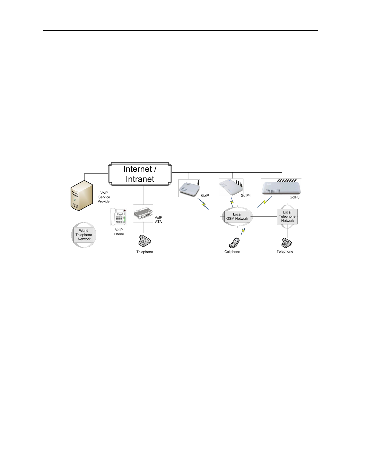
GoIP is the abbreviated from GSM over IP. It is a new type of VoIP gateway that allows call terminations from
a VoIP network to a GSM network and vice versa. Call connections between IP networks and GSM networks
are now bridged seamlessly to extend the voice communication coverage significantly. As the traditional
PSTN lines are starting to disappear in developed countries and are not going to be built extensively in
under-developed countries, GSM phones are getting more and more popular all over the world with lower and
lower service charges, the emergence of GoIP bridges the gap between the traditional telephone networks
and VoIP networks as shown in the diagram below. As a result, local and worldwide voice communications
are more convenience, lower cost, and broader coverage.
You can now make a call from anywhere in the world via a VoIP network and then terminate the call via a GoIP
to the local telephone network (PSTN). On the other hand, you can also make a call from the local telephone
network to a GoIP (the GSM phone number) and then dial another number via a VoIP network to anywhere in
the world. In these two cases, a VoIP Service provider is required for one side of the call termination. For
two fixed locations, it is possible to setup GoIPs at both ends for call terminations without subscribing to a
VoIP Service provider.
GoIP can also be used to achieve GSM roaming via VoIP. The idea is to route all your incoming GSM calls to a
GoIP via call forward or simply insert your SIM card to a GoIP. You can then setup the GoIP to forward all
incoming calls to another GSM number in the world via a VoIP service provider. The charge per call from a
VoIP service provider is significantly lower than the roaming charge.
For office environment, GoIP offers a quick way to replace the traditional PSTN lines or T1/E1 lines to your IP
PBX. There is no initial installation/reallocation charge and no need to wait for installation. Depending on
our usage, you can add or remove lines as per your requirement. You can even configure the system so that
everybody calls the same number regardless the number of lines available.

GoIP User Manual
http://www.dbltek.com
4
1.2 Protocols
TCP/IP V4 (IP V6 automatic adaptive)
Dual VoIP protocols: ITU-T H.323 V4, IETF SIP V2.0
Multiple Codecs: ITU-T G.711 Alaw/ULaw, G.729A, G.729AB, G.723.1 and GSM
H.2250 V4
H.245 V7
H.235 (MD5, HMAC-SHA1)
RFC1889 real-time digital transmission protocol
NAT
STUN
Network Management Protocol (NMP)
PPPoE Dial Up
PPP Authentication Protocol (PAP)
Internet Control Message Protocol (ICMP)
TFTP
Hypertext Transfer Protocol (HTTP)
Dynamic Host Configuration Protocol (DHCP)
Domain Name System (DNS)
User Account Authentication (via MD5)
Proprietary Relay Protocol (Avoiding VoIP Blockings)
1.3 Hardware Features
ARM processor
DSP for voice signal processing
Two 10/100MB Ethernet ports (IEEE 802.3 standard) with status LEDs
Quadband GSM module (850M 900M, 1800M and 1900M)
External Antenna (Internal Antenna option for selected models)
1.4 Software Features
LINUX OS
Built-in Web Server for device configuration
Built-in SIP Proxy (Simplified)
PPPoE Dial Up
Router function
DHCP client & Server
QoS (VLAN)
VPN (PPTP)
Online firmware upgrade
Remote Control Mechanism for remote technical support
Proprietary Auto Provisioning Mechanism
Remote SIM function
Short Messages (SMS) support (standalone and server based)
GoIP User Manual
http://www.dbltek.com
5
Call Management and Routing
1.5 Package Content
Use care when unpacking the device package in order to avoid damage to the main unit and the packing
materials. Retain the packing materials in case the unit is to be transported in the future.
Please inspect the shipping container and the contents for any damages. If visible damages are present,
please contact your vendor. Keep the shipping materials for the carrier inspection.
The package should contain the items listed in the table below
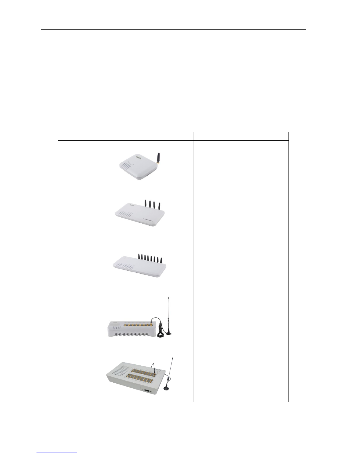
Item Appearance Description
1.
GoIP (1-Channel)
GoIP-4 (4-Channel)
GoIP-8 (8-Channel)
GoIP-16 (16-Channel)
GoIP-32 (32-Channel)
1 x Main Unit

GoIP User Manual
http://www.dbltek.com
6
2.
AC/DC Power Adapter:
GoIP1: 12V/500mA
GoIP4: 12V/2A
GoIP8: 12V/3A
GoIP16: 12V/4A
GoIP32: 12V/4.5A
3.
1 x Ethernet CAT5 Cable (2M)
1.6 LED Indicators
LED indicators (shown above for GoIP-8) are used to show the current status of the device. They are often used
to determine if the GoIP is working normally or not.
LED Label
Description
Power This LED is red and illuminates when power is connected.
LAN
This LED is red and illuminates when the LAN port is connected and blinks when data
transmission occurs.
PC
This LED is red and illuminates when the PC port is connected and blinks when data
transmission occurs.
RUN
This LED is green and blinks at a rate of every 100ms when VoIP is not ready for
making calls. (Fast Blink)
It blinks at a rate of every second when VoIP is ready for making calls (Slow Blink).
GoIP User Manual
http://www.dbltek.com
7
Channel “x”
Each GSM channel has its own status LED and its color is green.
1. It blinks at a rate of every 100ms (Fast blink) when the corresponding GSM
channel is not yet registered to a GSM network.
2. It blinks at a rate of every second (Slow blink) when the corresponding GSM
channel is ready for making or receiving calls (registered to a GSM network).
3. It illuminates when GSM call activities occurs (in use, ringing).
2 Installation
The same installation procedure applies for all models with the differences in the number of channels (ports)
available and the SIM card insertion. It is important to note that the power to the SIM slot MUST BE
disconnected/removed before removing or inserting a SIM Card. The power is removed by either
disconnecting the power to the GoIP or shutting each GSM module individually via its built-in web interface.
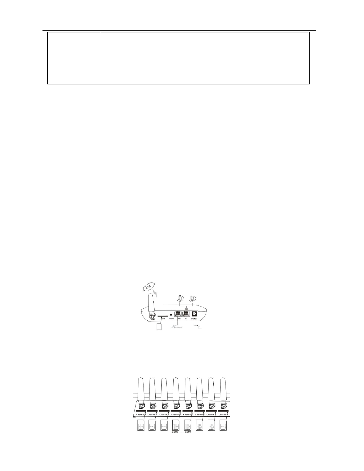
1. SIM card slots are located either at the bottom (for old hardware) or at the back (for new hardware) of the
main unit.
For the models with the SIM card slots located at the bottom, you need to open the bottom SIM cover in
order to install SIM cards. First slide the metal clip to the direction as indicated on the top of the clip.
Insert a SIM card to each slot carefully and then place the metal clip back in place.
For the models with the SIM card slots located at the back, just insert a SIM card to each slot as shown in
the drawing on the right. Please make sure that the orientation of the SIM Card is correct before
inserting the card.
For GoIP (1-channel), the SIM card insertion orientation is shown in the figure on the right. The metal
contacts must face down and the cut corner is inserted first.
For GoIP-4 and GoIP-8, the SIM card insertion orientation is shown in the figure on the right. The metal
contacts must face up and the cut corner is inserted first.

GoIP User Manual
http://www.dbltek.com
8
2. The LAN port is intended for intranet or internet connection. Depending on your network environment,
it can be connected various type of network equipment, such as network router, network switch / Hub,
xDSL/Cable modem, etc.
3. The PC port is intended for network sharing and it supports both bridge and router modes. In Bridge
mode, the PC port is connected to the same network segment as the LAN port. In Router mode, the PC
port is set to a different network segment. In this case, please make sure that the PC network segment IP
(192.168.x.) is different from the one in the LAN port network.
4. The DC port is for power connection. Please only use the AC/DC adapter provided. Adapter with
different rating or vendor may damage the device or affect its performance.
5. The Reset button is recessed inside the GoIP cabinet. You need to use a sharp pointer to access the
reset button. Press it momentarily to reboot the device. Press it for 15 seconds or more to reset the
device settings including login password to its factory defaults.

GoIP User Manual
http://www.dbltek.com
9
3 Configuration
The device can be configured via its built-in http web server or via an Auto Provision Server. Auto Provision
Server is a free utility supporting both Window and Linux OS. This utility is developed by DBL Technology for
the sole purpose of automating the configuration of our products. It is available in our website for free
download. This user manual only focuses on the device configuration via its built-in http web server.
Please note that only window based Web browsers, such as IE and Chrome are supported. Both Firefox and
Mozilla may not work properly depending on the version and the operating system used. If you are having
problems in configuring your device with your existing Web browser, please try one with lower version or a
different Web browser and report the problem to us.
3.1 HTTP WEB Server Login
There are two methods to access the built-in web server.
1. Method 1 is to access the built-in web server via the LAN port. The LAN port is set to DHCP mode as a
factory default. When you connect it to a network with a DHCP host, it will obtain an IP address from
the DHCP host automatically. Via the GoIP’s GSM channel(s), there are two ways to find out the IP
address that is assigned to this port.
i. Dial the SIM number of anyone of the GSM channels available. Once the call is answered, dial
“*01” to hear a voice prompt reporting the LAN port IP address.
ii. Send the “###INFO###” SMS command to one of the GSM channels available. The GoIP will then
return back the LAN port IP address. Please refer to Appendix A Special SMS Commands for more
information.
Once the LAN IP address is known, you are now ready to access its built-in http web server by typing its
IP address in the address field of a web browser.
2. Method 2 is to access the built-in we server via the PC port. As a factory default, the PC port IP is
preset to 192.168.8.1. Connect a computer to the LAN port of the device and configure its IP to
192.168.8.x (x = 2 to 254). Type the IP address 192.168.8.1 in the address field of a web browser.
Once the IP address is entered, the login window shown on the right pops up. Enter the user name and
password. There are three level of access via three
different user names.
1. Administrative Level -This offers a full access right
to all parameters available in the built-in webpage.
The user name and password for the
administrative level are "admin" and "admin"
respectively.
2. User Level - This level restricts user from
accessing the Call Setting page. User will not be
able to change any VoIP related settings. The
user name and password for the user level are
"user" and "1234" respectively.
3. SMS Level - This level only allows user to access
the Send SMS and SMS Box functions under the
Tool menu. The user name and password for the
SMS level is "sms" and "1234".
GoIP User Manual
http://www.dbltek.com
10
3.2 Status
There are four pages under the Status category and they are Summary, General, GSM, and SIM Call Forward.
Each page is refreshed every 5 seconds; however, this feature is not supported when the Firefox browser is
used. Sample pages shown in this section are captured from a GoIP-8. Please refer to the actual web
pages of the models of interest. It is important to understand the information shown in these pages in order
to debug or report problems encountered.
3.2.1Summary
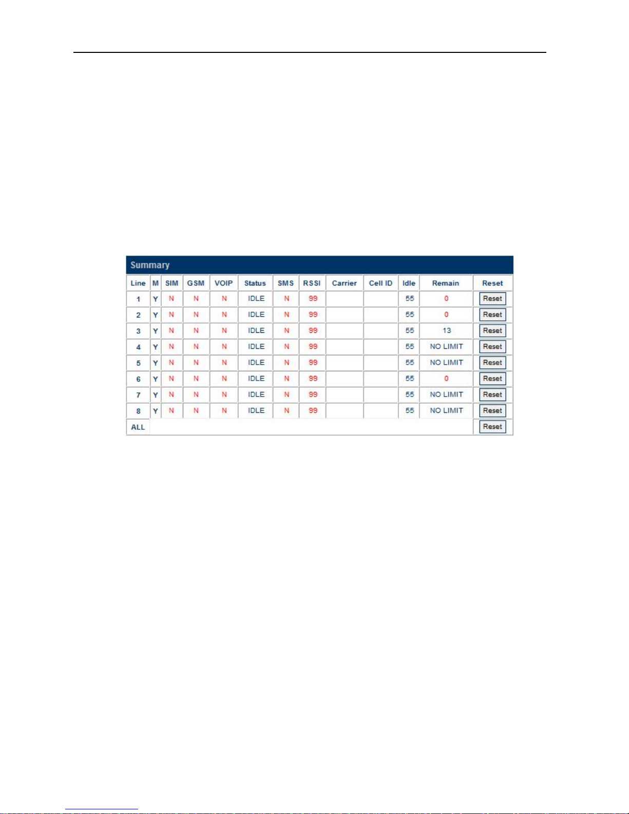
The current VoIP and GSM statuses are listed in the Summary page as shown below (extracted from GoIP-8) .
They are very essential to display the operation status of the GoIP in order to determine if it is working
properly or not.
Here are the list of GoIP parameters shown in this page.
1.CH - GoIP channel reference
2.M - GSM module status for the corresponding CH. "Y " means "Enabled" and "N" means "Disabled". If a
GSM module is disabled, all other parameters for this channel are not active. Clicking "Y" shuts down
the channel selected. Clicking "N" turns on the channel selected.
3.SIM - SIM card status. "Y" means that the corresponding GSM module can access the designated SIM card
successfully. "N" means unable to access the designated SIM card. Please check if the SIM card is
inserted properly or the SIM card is damaged. If Remote SIM function is used, please check the SIM
Bank and/or SIM Server configuration. The problem could also be caused by bad network condition or
improper network configuration.
4.GSM - GSM registration status. "Y " means "Registered" and "N" means "Not Registered".
5.VoIP - VoIP registration status. "Y " means "Registered" and "N" means "Not Registered". If GSM
Registration status is "N", VoIP registration is disabled and its status should be ignored.
6.Status - VoIP line status. If VoIP registration status is "N", the VoIP line status shown should be ignored.
Once VoIP registration status is "Y", the current VoIP line status is then shown in this field. Here are a
list of available statuses:
a. IDLE - The VoIP line is not engaged in any call activities.
b. CONNECTED - An active call between VoIP and GSM is in progress.
c. ACTIVE - A second dial tone is generated when a VoIP call is answered without making a GSM call or
when a GSM call is answered without making a VoIP call. The generation of a second dial tone
prompts the caller to press a phone number. The "Status" changes to "ACTIVE" since the start of
the second dial tone till a phone number is received for dialing or the call is terminated.
GoIP User Manual
http://www.dbltek.com
11
d. DIALING <phone number> - This occurs when the GoIP is dialing out a phone number via the
corresponding GSM channel or The DIALING status shows that a number is being dialed out via the
corresponding GSM channel or a VoIP line. The phone number dialed is also shown in the
"Status".
e. ALERTING - After a phone number is dialed, the "Status" changes to "ALERTING" when a ringback
signal is received from the network.
f. INCOMING - This occurs when a GSM incoming call is calling and the call is not answered yet.
7.SMS - SMS Server registration status. "Y " means "Registered" and "N" means "Not Registered".
8.RSSI - This indicates the Received Signal Strength Indicator of the current cell. It ranges from 0 to 31
which represents a signal level ranging from -113 dBm to -51 dBm; each increment in rssi values means
2 dBm increment. 99 means that the signal level is unknown or undetected.
9.Carrier - This shows the name of the current GSM carrier.
10. Cell ID - This shows the Base Transceiver station (BTS) ID.
11. Idle - This shows the time elapsed since the last call.
12. Remain - This shows the time remaining if the Total Talk Time Limit (m) is set. Once the Remain time
reaches zero, the corresponding channel is locked and its VoIP registration is also suspended (default
setting). However, there is an option in Section 3.3.10 to enable SIP registration even when the Talk
Time Limit expires ((Remain = 0).
13. Reset - Click this button to reset the Remain Timer to the Total Talk Time. Clicking on the Reset button
located at the bottom (the row that is labeled "All") resets all Remain Timers of all channels.
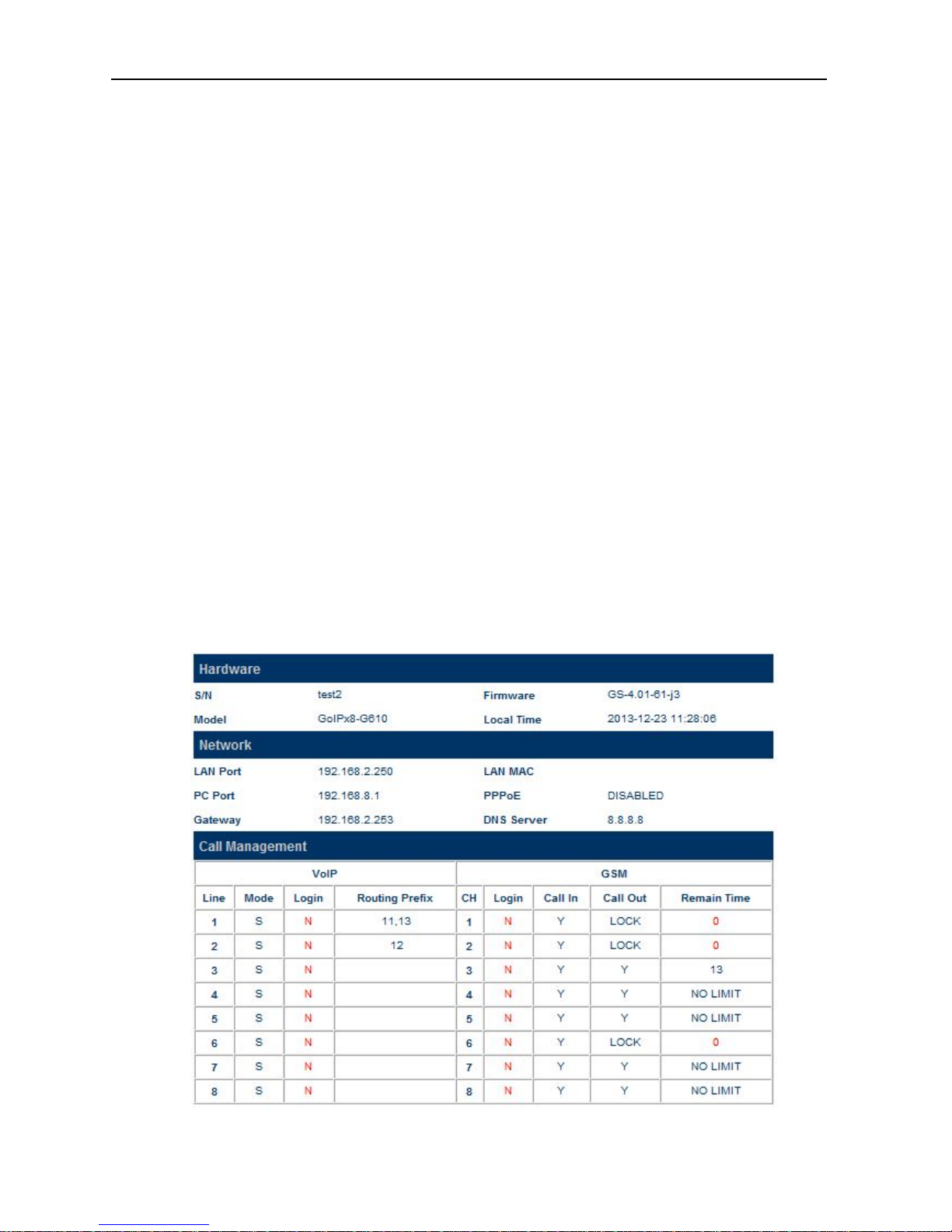
3.2.2 General
The General page covers basic information on the hardware, network, and call status and setting. These
information are useful for debugging the device operation and status.
1. Hardware

GoIP User Manual
http://www.dbltek.com
12
a) S/N – This field shows the serial number of the device.
b) Firmware – This field shows the current firmware version.
c) Model – This field shows the model number of the device
d) Local Time - This shows the current system time. It is a good indication for normal network access
provided that the network server address and time zone are set properly.
Please make sure that these information are provided when reporting a problem or requesting for
technical support.
2. Network
a) LAN Port – This field shows the IP address assigned to the LAN Port.
b) LAN MAC - This field shows the physical hardware address (MAC) assigned to the LAN port.
c) PC Port – This field shows the IP address assigned to the PC Port.
d) PPPoE – This field shows the PPPoE dial up status. It is only meaningful when PPPoE is enabled.
e) Gateway – This field shows the default gateway IP assigned for data traffic routing.
f) DNS Server – This field shows the current DNS server assigned for domain name interpretation. It
is possible that some domain names are blocked by local DNS servers. Changing this to an
overseas DNS server may solve the problem.
g) VPN Status - This shows the current VPN connection status. It only appears when VPN is enabled.
3. Call Management section summarizes the both GoIP and GSM configurations and their corresponding
status. It is important to note that the VoIP lines and the GSM channels are not mapped to each other
as a one to one relationship. For outgoing calls (from VoIP to GSM), the GSM channel selection is
based on the Routing Prefix.
VoIP
a) Line - This is used as a reference in VoIP line configuration.
b) Mode - This shows the current VoIP Registration mode. "S" means Single Server Mode. "L"
means Config. By Line mode. "Gx" means Config. by Group mode where x is the group reference
number. "T" means Trunk Gateway mode.
c) Login - This shows the current VoIP registration status. "Y" means that the corresponding line
registers to the server successfully. "N" means the corresponding line fails to register to the server.
d) Routing Prefix - This shows the current setting for the Routing Prefix. Please refer to Section 3.3.3
for more information.
GSM
e) CH - This corresponds to the physical GSM channel number.
f) Login - This shows the current GSM Registration status for voice calls.
g) Call In - This shows the Call IN setting for the corresponding GSM channel. "Y" means incoming
calls are enabled. "N" means incoming calls are disabled and the corresponding channel rejects all
incoming calls by sending back the hangup ("ATH") command to the GSM network.
h) Call Out - This shows the Call Out setting for the corresponding GSM channel. "Y" means outgoing
calls are enabled and "N" means outgoing calls are disabled. When the Remain Time for outgoing
calls reaches zero, the Call Out setting is set to "LOCK" automatically. To unlock the channel, click
the corresponding [Reset] button in the Summary page.
i) Remain Time - This is the same as the "Remain" shown in the Summary page. If the Talk Time
Limit in the SIM Page is set, this parameter shows the remaining time allowed for outgoing calls.
GoIP User Manual
http://www.dbltek.com
13
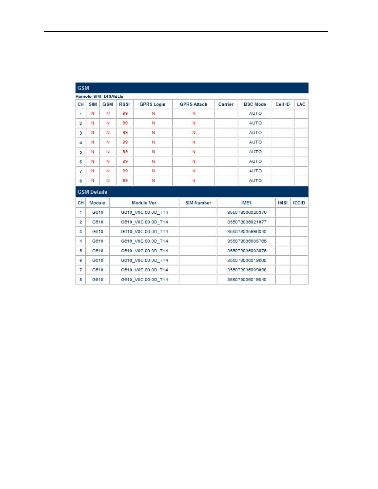
3.2.3GSM
The GSM page shows the current GSM channels status and information on the GSM modules and the SIM
cards inserted.
The top table shows a number of GSM parameters which are useful to determine if the GSM channels in the
gateway are working properly.
1. Remote SIM - This tells if Remote SIM function is used or not. "DISABLE" means using the local SIM cards
that are inserted to the GoIP.
2. SIM - "Y" means the corresponding GSM module is able to access the designated SIM card properly.
3. GSM - "Y" means the corresponding GSM module registers to the GSM network successfully.
4. RSSI - Received Signal Strength Indicator. Please see the description in Section 3.1.1.
5. GPRS Login - "Y" means access to a GPRS network. This status is obtained from the command AT+CREG.
6. GPRS Attach - "Y" means GPRS Attach is successful and is ready for PDP. This status is obtained from the
command AT+CGATT.
7. Carrier - This shows the name of the current GSM carrier.
8. GSM BSC mode - This shows the current setting for the GSM BSC mode which determines how the GoIP
selects a base station. For more information, please refers to the section 3.3.15.
9. Cell ID - This shows the Base Transceiver Station (BTS) ID.
10. LAC - This shows the Location Area Code.
The bottom table shows more detailed information on the onboard GSM modules and the SIM card inserted.
GoIP User Manual
http://www.dbltek.com
14
1. Module - The model number of the GSM module.
2. Firmware Ver - The version number of the firmware installed in the module.
3. SIM Number - The GSM number that is assigned to the SIM card. User must enter this number manually.
4. IMEI - International Mobile Station Equipment Identity
5. IMSI - International Mobile Subscriber Identity
6. ICCID - Integrated Circuit Card Identifier
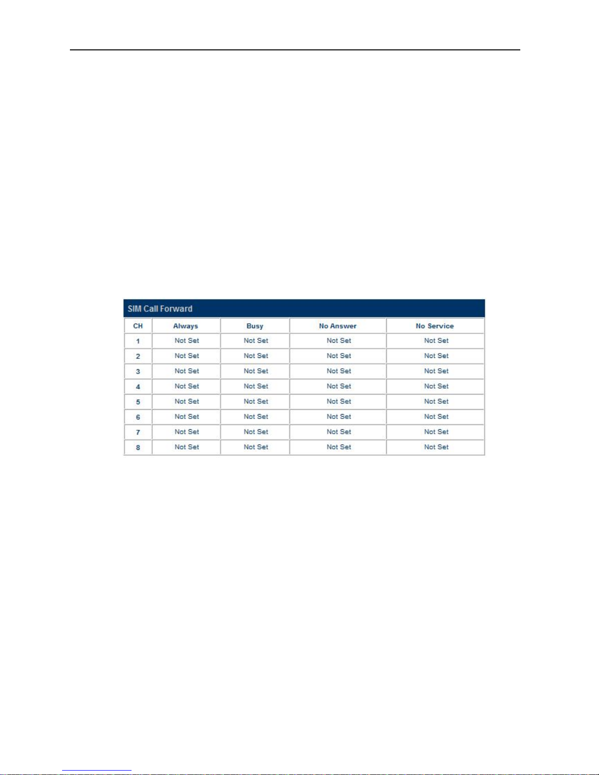
3.2.4SIM Call Forward
The table below lists the current call forward settings of the SIM card assigned to the corresponding channel.
There are 3 possible status:
1. ON - This means that the corresponding Call Forward mode is enabled and this setting is sent to the GSM
network when a new GSM registration takes place.
2. OFF - This means that the corresponding Call Forward mode is disabled and this setting is sent to the GSM
network when a new GSM registration takes place.
3. Not Set - This means that there is no change to the current Call Forwarding mode and nothing is sent to the
GSM network when a new GSM registration takes place. This is useful by leaving the current Call
Forward mode unchanged.

GoIP User Manual
http://www.dbltek.com
15
3.3 Configuration
Click “Configuration” on the left hand column to display the Configuration page and the following submenu.
1. Preference
2. Network
3. Basic VoIP
4. Advance VoIP
5. Media
6. Call Out
7. Call Out Auth.
8. Call In
9. Call In Auth.
10. SIM
11. SIM Forward
12. IMEI
13. SMS
14. GSM Carrier
15. GSM Base Station
GoIP User Manual
http://www.dbltek.com
16
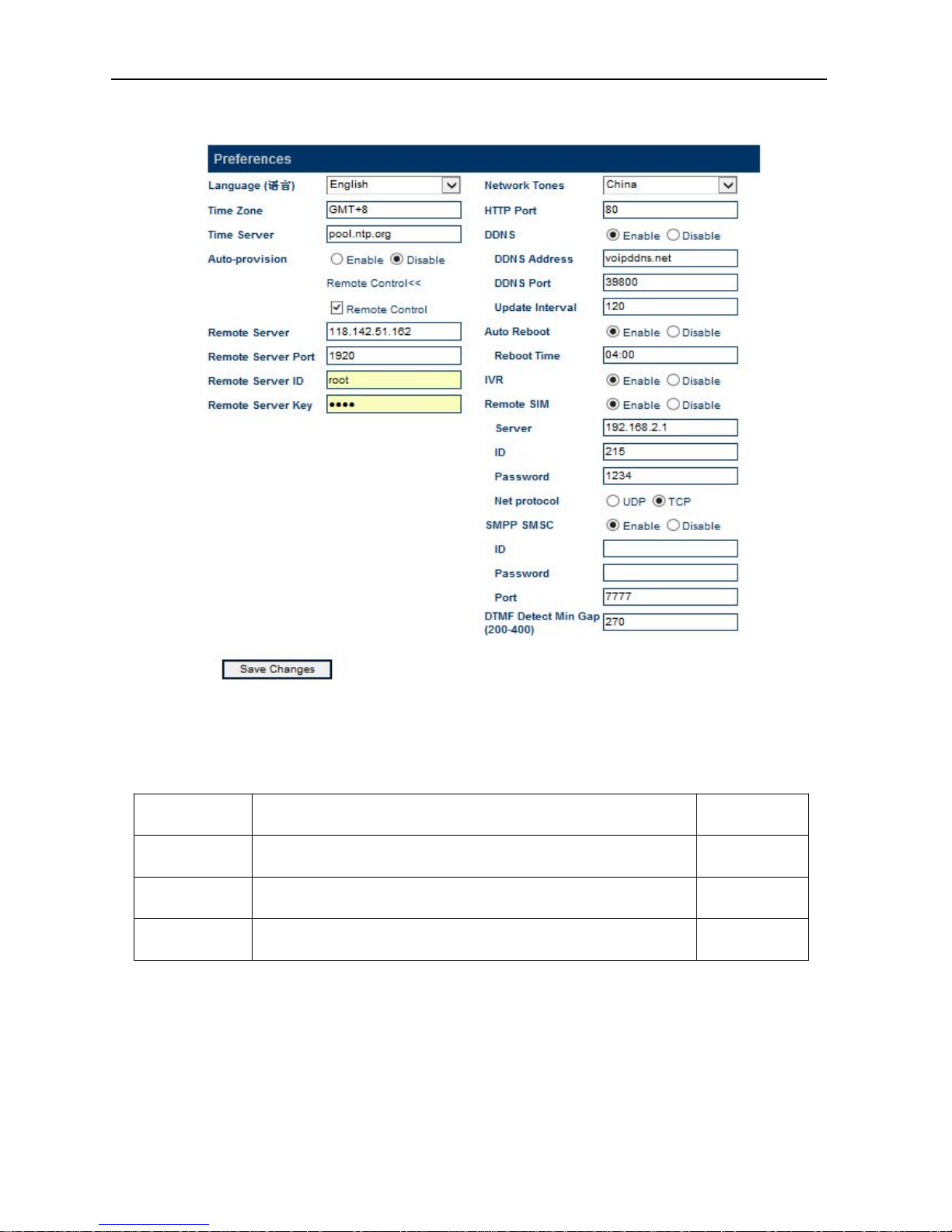
3.3.1Preference
The preference page shown above consists of the following system level parameters and options as shown in
the table below.
Parameter
(Preference)
Description Default Value
1. Language This sets the webpage and voice prompts language. Currently, only English
and Simplified Chinese (Mandarin for voice prompt) are supported.
English
2. Time Zone This specifies the offset of the local time zone with respect to GMT. The syntax
should be “GMT
x” where x is the offset.
3. Time Server This specifies IP address or the domain name of a network time server for
computer clock synchronization. The default is “pool.ntp.org”.
pool.ntp.org

GoIP User Manual
http://www.dbltek.com
17
4. Auto-provision
Provision Server
Provision Interval
The auto provision is optional. When this option is enabled, the device
downloads its configuration from the Auto Provision Server at start up or at the
time interval specified by the Provision Interval. The configuration file name is
<Serial Number>.cfg which is just a text file (not encrypted). If encrypted
format is required, please contact technical support for further assistance.
Please note that Auto Provision Server is a free utility supporting both Linux and
Window environment. Please visit our website or contact technical support
for more information.
The specifies the Provision Sever address (IP or Domain name)
This specifies the interval in performing an auto provisioning event.
5. Remote Control
Remote Server
Remote Server
Port
Remote Server ID
Remote Server
Password
This is a unique feature that allows remote access to the device's built-in Web
server even when it is installed behind NAT. To achieve this function, a Remote
Control Server is required to be installed. This server is a free Linux based
utility and is available for download via our website. Please contact technical
support for further assistance if required. Once installed, please make sure
that the Remote Server Port and Password are set properly.
This specifies the IP address or the domain of the Remote Control Server.
Check with your Remote Server administrator for the communication port.
This specifies the name to be appeared in the Remote Control Server. It is used as a
reference for the device.
This specifies the login password to the Remote Control Server. This is not the password
to login to the built-in webpage. Please ask your Remote Server Administrator if it is not
available.
1920
6. Network Tones Network tones are the tones associated with the traditional (PSTN) telephone
network, such as dial tone, ring back tone, busy tone, call waiting tones, etc.
These tones will only be used when the device answers an incoming call and the
call is not forwarded to a SIP server automatically. Predefined Network Tones
are classified by country name. If the country desired is not found in the list,
the “Custom” selection allows users to define the network tones individually.
Please refer to Appendix B for more information.
7. HTTP Port This sets the port that is used to access the built-in web server. The default
port number is 80. The port range is from 1 to 65535.
8. DDNS
DDNS Address
DDNS Port
Update Interval
This is a proprietary DDNS service offered by DBL. It allows DBL's products to
identify each other via this DDNS service. When this service is activated, the
domain name of the device is its <serial number>.com. This feature is useful
to support peer-to-peer configuration.
The default DDNS Address is “voipddns.net” which a free service offered by DBL. Please
contact your vendor if you want to install your own DDNS server.
The default communication port number is 39800.
This specifies the interval between registrations to the DDNS.
voipddns.net
39800
120 (mins)
GoIP User Manual
http://www.dbltek.com
18
9. Auto Reboot
Reboot Time
This option allows the device to reboot itself at the time defined by Reboot
Time.
This parameter specifies the time to reboot the device. Two formats are supported:
1. HH:MM - When this is specified with a valid 24-hr time format (00:00 to 23:59), the
goip is rebooted at this specified time. Invalid time specified has no effect.
2. M - This specifies the reboot duration in minutes. The valid range for this is from 0 to
x.
Changes saved are only effective after the device is rebooted.
Disabled
10. IVR The device is equipped with a simple voice prompt. When this option is
enabled and a call is answered, the device plays a voice prompt instead of a dial
tone to the caller.
Enabled
11. Remote SIM
Server
ID
Password
Net Protocol
Only the GoIPs with the serial number xxxx support the Remote SIM feature.
Enabling this feature allows the SIM Cards to be installed in a SIM Bank rather
than in the on-board SIM slots. GoIP can either register to a SIM Bank or a SIM
Server. Please refer to the SIM Bank User Manual for more information.
This specifies the IP address of the SIM Bank or the SIM Server.
This specifies the name to be appeared in the SIM Bank or the SIM Server.
This specifies the login password to the SIM Bank or the SIM Server.
Specify the network protocol (UDP or TCP) is used for Remote SIM communications.
Disabled
12. SMPP SMSC This parameter enables the support of SMPP protocol. Please note that GoIP
is acting as a SMSC (Short Message Service Center). Fill in the SMPP ID,
Password, and port number for SMPP data communications.
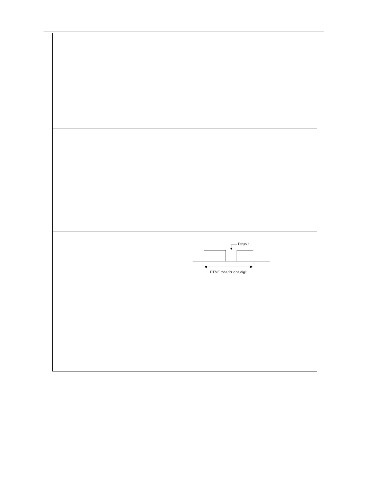
13. DTMF Tone
Min Gap (200 -
400)
This parameter specifies the maximum dropout time for a DTMF tone.
When making a call from SIP to GSM or
from GSM to SIP by using the second dial
method, the device needs to detect the
dialing digits from the DTMF tones
received via the voice data stream.
Depending on the network conditions, short dropouts may occur due to packet
jitter / loss. Therefore, DTMF digit may be detected more than once if these
dropouts are not taken into account. Consequently, the call is dialed to an
incorrect number. To avoid this problem, a dropout window is used to avoid
false detection when dropouts occur. During this window, the same DTMF
digit is not recognized more than once.
The range of the dropout window is specified in terms of packet timestamp
value. The smaller the value is, the smaller the dropout window is. This
increase the chance of detecting the same digit twice or more. However, if the
value is set too large, there is a possibility that the next digit is missed.
270
3.3.2Network
Proper network environment is the key to insure the voice call performance of the device. In general,
Intranet offers a more stable network environment than Internet and it is the preferred network to be used.
If Internet is going to be used, please make sure that the network can offer low packet loss, small packet jitter
and low packet delay. Each voice channel requires less than 90 kbps when A-law or
-law voice codec is
used. GoIP-8 will require 8 times this bandwidth. Therefore, it is very important to make that both
upstream and downstream have enough bandwidth (+ 30% headroom) in order to accommodate the data
 Loading...