

SGS-CSTC Standards Technical Services Co., Ltd.
Shenzhen Branch
Report No.: SZEM190301137601
Page: 1 of 17
TEST REPORT
Application No.: SZEM1903011376CR
Applicant: SHENZHEN DBK ELECTRONICS CO., LTD
Address of Applicant: No.8 Qinghua Road, Zhu Village, Fucheng New Community, Guanlan Street,
Longhua District, Shenzhen City, Guangdong Province, China
Manufacturer: SHENZHEN DBK ELECTRONICS CO., LTD.
Address of Manufacturer: Room No.208-1, 308, 404-408 in Building Five, 2-4 Floor in Building Three,
No.8 Qinghua Road, Zhu Village, Fucheng New Community, Guanlan Street,
Longhua Disstrict, Shenzhen City, Guangdong Province, P.R.China
Factory: SHENZHEN DBK ELECTRONICS CO., LTD.
Address of Factory: Room No.208-1, 308, 404-408 in Building Five, 2-4 Floor in Building Three,
No.8 Qinghua Road, Zhu Village, Fucheng New Community, Guanlan Street,
Longhua Disstrict, Shenzhen City, Guangdong Province, P.R.China
Equipment Under Test (EUT):
EUT Name: Wireless charger
Model No.: CP6732-RZ
Trade mark: DBK
FCC ID: 2ARVRCP6732
Standard(s) :
Date of Receipt:
Date of Test:
Date of Issue:
Test Result:
* In the configuration tested, the EUT complied with the standards specified above.
47 CFR Part 18
2019-03-06
2019-03-12 to 2019-03-26
2019-05-08
Pass*
Keny Xu
EMC Laboratory Manager
SGS-CSTC Standards Technical Services Co., Ltd.
Shenzhen Branch
Report No.: SZEM190301137601
Page: 2 of 17
Revision Record
Version
01 2019-05-08 Original
Authorized for issue by:
Chapter Date Modifier Remark
Leo Li /Project Engineer
Eric Fu /Reviewer
2 Test Summary
Radio Spectrum Matter Part
Item Standard Method Requirement Result
Conducted
disturbance
Radiated emission 47 CFR Part 18 FCC MP-5 Part 18.305 Pass
SGS-CSTC Standards Technical Services Co., Ltd.
Shenzhen Branch
Report No.: SZEM190301137601
Page: 3 of 17
47 CFR Part 18 FCC MP-5 Part 18.307 Pass
SGS-CSTC Standards Technical Services Co., Ltd.
Shenzhen Branch
Report No.: SZEM190301137601
Page: 4 of 17
3 Contents
Page
1 COVER PAGE ............................................................................................................................................ 1
2 TEST SUMMARY ....................................................................................................................................... 3
3 CONTENTS ................................................................................................................................................ 4
4 GENERAL INFORMATION ........................................................................................................................ 5
4.1 DETAILS OF E.U.T. ............................................................................................................................... 5
4.2 DESCRIPTION OF SUPPORT UNITS ......................................................................................................... 5
4.3 MEASUREMENT UNCERTAINTY .............................................................................................................. 5
4.4 TEST LOCATION .................................................................................................................................... 6
4.5 TEST FACILITY ...................................................................................................................................... 6
4.6 DEVIATION FROM STANDARDS ............................................................................................................... 6
4.7 ABNORMALITIES FROM STANDARD CONDITIONS ..................................................................................... 6
5 EQUIPMENT LIST ...................................................................................................................................... 7
6 RADIO SPECTRUM MATTER TEST RESULTS ....................................................................................... 8
6.1 CONDUCTED DISTURBANCE ................................................................................................................... 8
6.1.1 E.U.T. Operation ............................................................................................................................ 8
6.1.2 Test Setup Diagram ....................................................................................................................... 8
6.1.3 Measurement Procedure and Data............................................................................................... 9
6.2 RADIATED EMISSION ........................................................................................................................... 12
6.2.1 E.U.T. Operation .......................................................................................................................... 13
6.2.2 Test Setup Diagram ..................................................................................................................... 13
6.2.3 Measurement Procedure and Data............................................................................................. 13
7 PHOTOGRAPHS ...................................................................................................................................... 17
7.1 TEST SETUP ....................................................................................................................................... 17
7.2 EUT CONSTRUCTIONAL DETAILS (EUT PHOTOS) ................................................................................. 17

4 General Information
SGS-CSTC Standards Technical Services Co., Ltd.
Shenzhen Branch
Report No.: SZEM190301137601
Page: 5 of 17
4.1 Details of E.U.T.
Power supply: Input: DC 5V/2A, DC 9V/1.67A
Output:
WPC: 5W(DC 5V/1A), 7.5W(DC 5V/1.5A), 10W(DC 9V/1.1A)
Cable: USB cable: 100cm shielded
Antenna Type: Loop Antenna
Modulation Type: Load Modulation
Operation Frequency: 109.21kHz to 178.68kHz
Remark:
4.2 Description of Support Units
Description Manufacturer Model No. Serial No.
iPhone 8 Apple A1863 F4GVQ656JC6D
Mobile Phone SAMSUNG SM-G9500 R28J9140LPB
USB Adapter Client supplied KA1803A-EU N/A
iPhone 8 Apple A1863 F4GVQ656JC6D
4.3 Measurement Uncertainty
No. Item Measurement Uncertainty
1 Conduction Emission ± 3.0dB (150kHz to 30MHz)
2 Radiated Spurious emission test
3 Temperature test ± 1°C
4 Humidity test ± 3%
5 Supply voltages ± 1.5%
6 Time ± 3%
Tests were conducted in all three load modes and the worst case 10W(DC
9V/1.1A) is reported only.
± 4.5dB (Below 1GHz)
± 4.8dB (Above 1GHz)

SGS-CSTC Standards Technical Services Co., Ltd.
Shenzhen Branch
Report No.: SZEM190301137601
Page: 6 of 17
4.4 Test Location
All tests were performed at:
SGS-CSTC Standards Technical Services Co., Ltd., Shenzhen Branch
No. 1 Workshop, M-10, Middle Section, Science & Technology Park, Shenzhen, Guangdong, China.
518057.
Tel: +86 755 2601 2053 Fax: +86 755 2671 0594
No tests were sub-contracted.
4.5 Test Facility
The test facility is recognized, certified, or accredited by the following organizations:
• CNAS (No. CNAS L2929)
CNAS has accredited SGS-CSTC Standards Technical Services Co., Ltd. Shenzhen Branch EMC
Lab to ISO/IEC 17025:2005 General Requirements for the Competence of Testing and Calibration
Laboratories (CNAS-CL01 Accreditation Criteria for the Competence of Testing and Calibration
Laboratories) for the competence in the field of testing.
• A2LA (Certificate No. 3816.01)
SGS-CSTC Standards Technical Services Co., Ltd., Shenzhen EMC Laboratory is accredited by the
American Association for Laboratory Accreditation(A2LA). Certificate No. 3816.01.
• VCCI
The 3m Fully-anechoic chamber for above 1GHz, 10m Semi-anechoic chamber for below 1GHz,
Shielded Room for Mains Port Conducted Interference Measurement and Telecommunication Port
Conducted Interference Measurement of SGS-CSTC Standards Technical Services Co., Ltd. have
been registered in accordance with the Regulations for Voluntary Control Measures with Registration
No.: G-20026, R-14188, C-12383 and T-11153 respectively.
• FCC –Designation Number: CN1178
SGS-CSTC Standards Technical Services Co., Ltd., Shenzhen EMC Laboratory has been recognized
as an accredited testing laboratory.
Designation Number: CN1178. Test Firm Registration Number: 406779.
• Innovation, Science and Economic Development Canada
SGS-CSTC Standards Technical Services Co., Ltd., Shenzhen EMC Laboratory has been recognized
by ISED as an accredited testing laboratory.
CAB identifier: CN0006.
IC#: 4620C.
4.6 Deviation from Standards
None
4.7 Abnormalities from Standard Conditions
None

SGS-CSTC Standards Technical Services Co., Ltd.
Shenzhen Branch
Report No.: SZEM190301137601
Page: 7 of 17
5 Equipment List
Conducted disturbance
Equipment Manufacturer Model No Inventory No Cal Date Cal Due Date
Shielding Room ChangZhou ZhongYu
Measurement Software
Coaxial Cable SGS N/A SEM024-01 2018-07-12 2019-07-11
LISN Rohde & Schwarz ENV216 SEM007-01 2018-09-25 2019-09-24
LISN ETS-LINDGREN 3816/2 SEM007-02 2019-04-01 2020-03-31
EMI Test Receiver Rohde & Schwarz ESCI SEM004-02 2019-04-01 2020-03-31
Radiated emission
Equipment Manufacturer Model No Inventory No Cal Date Cal Due Date
10m Semi-Anechoic
Chamber
Measurement Software
Coaxial Cable SGS N/A SEM029-01 2018-07-12 2019-07-11
EMI Test Receiver
(9kHz-7GHz)
Trilog-Broadband
Antenna
(30MHz-1GHz)
Pre-amplifier
Active Loop Antenna ETS-Lindgren 6502 SEM003-08 2017-08-22 2020-08-21
General used equipment
Equipment Manufacturer Model No Inventory No Cal Date Cal Due Date
Humidity/ Temperature
Indicator
Humidity/ Temperature
Indicator
Humidity/ Temperature
Indicator
Barometer
AUDIX e3 V5.4.1221d
SAEMC FSAC1018 SEM001-03 2018-03-31 2021-03-30
AUDIX
Rohde & Schwarz ESR SEM004-03 2019-04-01 2020-03-31
Schwarzbeck VULB9168 SEM003-18 2016-06-29 2019-06-28
Sonoma Instrument
Co
Shanghai
Meteorological
Industry Factory
Shanghai
Meteorological
Industry Factory
Mingle N/A SEM002-08 2018-09-27 2019-09-26
Changchun
Meteorological
Industry Factory
GB-88 SEM001-06 2017-05-10 2020-05-09
N/A N/A N/A
e3 V8.2014-6-
27
310N SEM005-04 2019-04-12 2020-04-11
ZJ1-2B SEM002-03 2018-09-27 2019-09-26
ZJ1-2B SEM002-04 2018-09-27 2019-09-26
DYM3 SEM002-01 2019-04-04 2020-04-03
N/A N/A N/A

% RH
SGS-CSTC Standards Technical Services Co., Ltd.
Shenzhen Branch
6 Radio Spectrum Matter Test Results
6.1 Conducted disturbance
Test Requirement Part 18.307
Test Method: FCC MP-5
Limit:
Frequency of emission (MHz)
0.15-0.5 66 to 56* 56 to 46*
0.5-5 56 46
5-30 60 50
*Decreases with the logarithm of the frequency.
6.1.1 E.U.T. Operation
Operating Environment:
Temperature: 21.3
Test mode a:Charge mode_Keep the EUT charging
6.1.2 Test Setup Diagram
°C Humidity:
56
Atmospheric Pressure: 1015 mbar
Report No.: SZEM190301137601
Page: 8 of 17
Conducted limit (dBµV)
Quasi-peak Average

SGS-CSTC Standards Technical Services Co., Ltd.
Shenzhen Branch
Report No.: SZEM190301137601
Page: 9 of 17
6.1.3 Measurement Procedure and Data
1) The mains terminal disturbance voltage test was conducted in a shielded room.
2) The EUT was connected to AC power source through a LISN 1 (Line Impedance Stabilization
Network) which provides a 50ohm/50µH + 5ohm linear impedance. The power cables of all other
units of the EUT were connected to a second LISN 2, which was bonded to the ground reference
plane in the same way as the LISN 1 for the unit being measured. A multiple socket outlet strip was
used to connect multiple power cables to a single LISN provided the rating of the LISN was not
exceeded.
3) The tabletop EUT was placed upon a non-metallic table 0.8m above the ground reference plane.
And for floor-standing arrangement, the EUT was placed on the horizontal ground reference plane,
4) The test was performed with a vertical ground reference plane. The rear of the EUT shall be 0.4 m
from the vertical ground reference plane. The vertical ground reference plane was bonded to the
horizontal ground reference plane. The LISN 1 was placed 0.8 m from the boundary of the unit under
test and bonded to a ground reference plane for LISNs mounted on top of the ground reference
plane. This distance was between the closest points of the LISN 1 and the EUT. All other units of the
EUT and associated equipment was at least 0.8 m from the LISN 2.
5) In order to find the maximum emission, the relative positions of equipment and all of the interface
cables must be changed according to ANSI C63.10 on conducted measurement.
Remark: LISN=Read Level+ Cable Loss+ LISN Factor
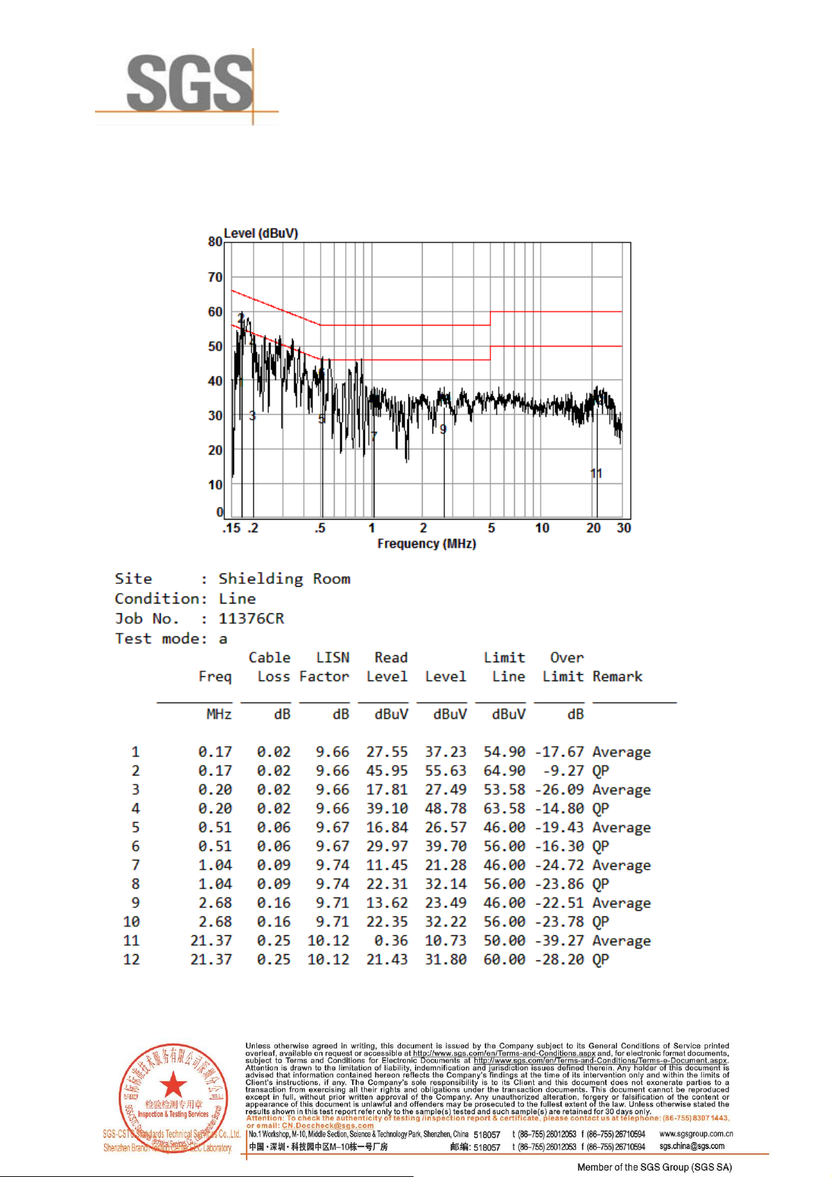
Mode:a; Line:Live Line
SGS-CSTC Standards Technical Services Co., Ltd.
Shenzhen Branch
Report No.: SZEM190301137601
Page: 10 of 17
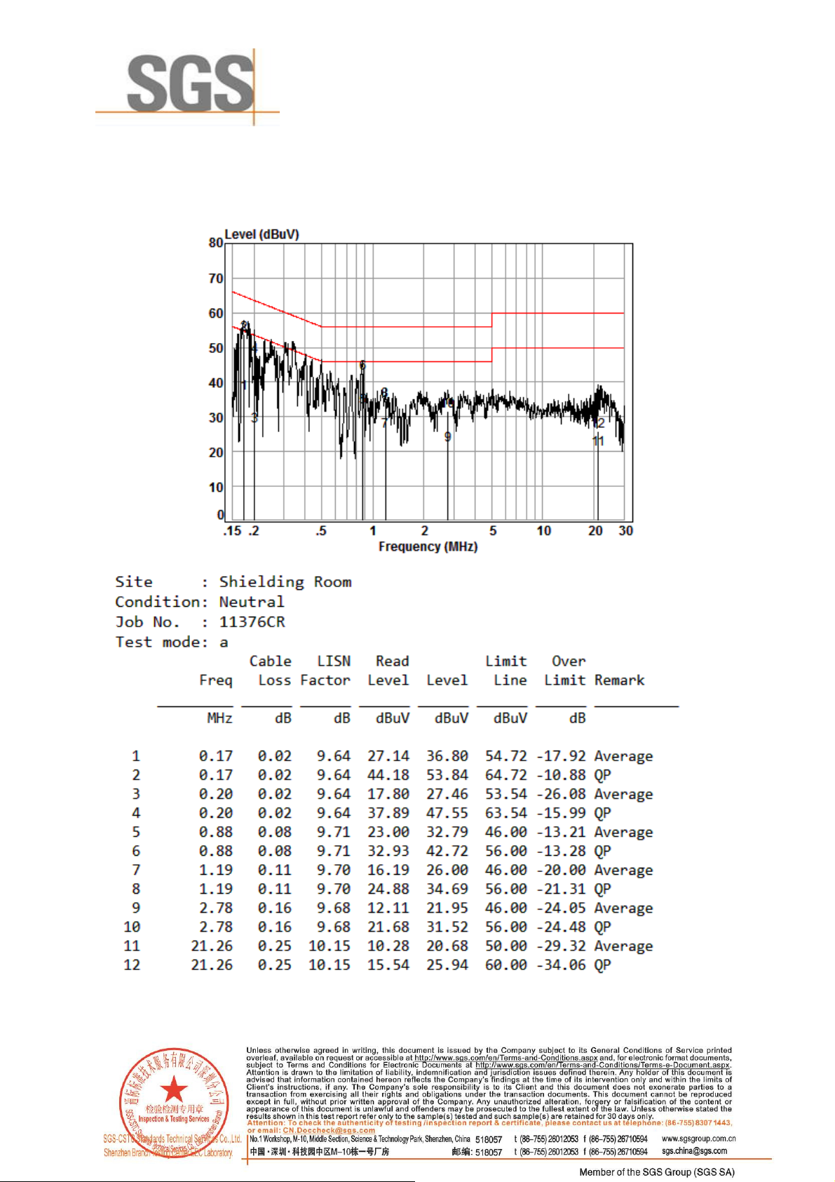
Mode:a; Line:Neutral Line
SGS-CSTC Standards Technical Services Co., Ltd.
Shenzhen Branch
Report No.: SZEM190301137601
Page: 11 of 17

6.2 Radiated emission
Test Requirement Part 18.305
Test Method: FCC MP-5
Measurement Distance: 3m
Frequncy range 9KHz-30MHz
Limit:
SGS-CSTC Standards Technical Services Co., Ltd.
Shenzhen Branch
Report No.: SZEM190301137601
Page: 12 of 17
1
Field strength may not exceed 10 µV/m at 1600 meters. Consumer equipment operating below 1000
MHz is not permitted the increase in field strength otherwise permitted here for power over 500 watts.
2
Reduced to the greatest extent possible.
3
Field strength may not exceed 10 µV/m at 1600 meters. Consumer equipment is not permitted the
increase in field strength otherwise permitted here for over 500 watts.
4
Induction cooking ranges manufactured prior to February 1, 1980, shall be subject to the field strength limits
for miscellaneous ISM equipment.
Remark:
1 This product belongs to non-ISM equipment, the field strength limit is 15uV/m at 300 meter distance.
2 Limit: 20log(15uV/m) +20log (300/3) =23.52+40=63.52dBuV/m at 3 meters distance

% RH
SGS-CSTC Standards Technical Services Co., Ltd.
Shenzhen Branch
6.2.1 E.U.T. Operation
Operating Environment:
Temperature: 25
Test mode a:Charge mode_Keep the EUT charging
6.2.2 Test Setup Diagram
°C Humidity:
51
Report No.: SZEM190301137601
Page: 13 of 17
Atmospheric Pressure: 1015 mbar
6.2.3 Measurement Procedure and Data
Test Procedure: a. The EUT was placed on the top of a rotating table 0.8 meters above the
ground at a 3 meter semi-anechoic chamber(30MHz-1000MHz) and 3 meter
semi-anechoic chamber(9kHz-30MHz). The table was rotated 360 degrees to
determine the position of the highest radiation.
b. The EUT was set 10 meters(30MHz-1000MHz) and 10 meter (9kHz-30MHz)
away from the interference-receiving antenna, which was mounted on the top
of a variable-height antenna tower.
c. Above 30MHz: The Analyzer/Receiver scanned from 30MHz to 1000MHz.The
antenna height is varied from one meter to four meters above the ground to
determine the maximum value of the field strength. Both horizontal and
vertical polarizations of the antenna are set to make the measurement.
d. Below 30MHz: The Analyzer/Receiver scanned from 9kHz to 30MHz.The
antenna height is 2 meters above the ground to determine the maximum

SGS-CSTC Standards Technical Services Co., Ltd.
Shenzhen Branch
Report No.: SZEM190301137601
Page: 14 of 17
value of the field strength.
e. For each suspected emission, the EUT was arranged to its worst case and
then the antenna was tuned to heights from 1 meter to 4 meters (for the test
frequency of below 30MHz, the antenna was tuned to heights 2 meter) and
the rotatable table was turned from 0 degrees to 360 degrees to find the
maximum reading.
f. The test-receiver system was set to Peak Detect Function and Specified
Bandwidth with Maximum Hold Mode.
g. If the emission level of the EUT in peak mode was 10dB lower than the limit
specified, then testing could be stopped and the peak values of the EUT
would be reported. Otherwise the emissions that did not have 10dB margin
would be re-tested one by one using peak, quasi-peak or average method as
specified and then reported in a data sheet.
h. Repeat above procedures until all frequencies measured was complete.
i. Measurement Requirement:
1)This product belongs to non-ISM equipment, the field strength limit is 15uV/m at
300 meter distance.
2)Limit: 20log(15uV/m) +20log (300/3) =23.52+40=63.52dBuV/m at 3 meters
distance.

Mode a:
9kHz-150kHz
SGS-CSTC Standards Technical Services Co., Ltd.
Shenzhen Branch
Report No.: SZEM190301137601
Page: 15 of 17

Mode a:
150kHz-30MHz
SGS-CSTC Standards Technical Services Co., Ltd.
Shenzhen Branch
Report No.: SZEM190301137601
Page: 16 of 17

SGS-CSTC Standards Technical Services Co., Ltd.
Shenzhen Branch
Report No.: SZEM190301137601
Page: 17 of 17
7 Photographs
7.1 Test Setup
Refer to Setup Photos
7.2 EUT Constructional Details (EUT Photos)
Refer to EUT external and internal photos
- End of the Report -
 Loading...