

Page 1
© Copyright 2002 DB Industries, Inc.
User Instruction Manual
Tripod Anchorage Connectors
This manual is intended to meet the
Manufacturer's Instructions as required by
ANSI Z359.1 and ANSI A10.14, and
should be used as part of an employee
training program as required by OSHA.
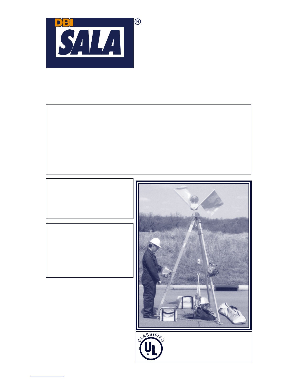
The 8000000 and 8000010 Tripods
are Classified by Underwriters
Laboratories Inc. as to the 350 lb.
load capacity only.
WARNING:
This product is part of a personal fall arrest, work positioning,
personnel riding, material handling, or rescue and evacuation system. The
user must read and follow the manufacturer's instructions for each
component or part of the complete system. These instructions must be
provided to the user of this equipment. The user must read and understand
these instructions or have them explained to them before using this
equipment. Manufacturer's instructions must be followed for proper use and
maintenance of this product. Alterations or misuse of this product or failure to
follow instructions may result in serious injury or death.
IMPORTANT:
If you have any
questions on the use, care,
application, or suitability for
use of this safety equipment,
contact DBI/SALA immediately.
IMPORTANT :
Before using this
equipment, record the product
identification information found
on the ID label of the tripod on
the inspection and maintenance
log in section 9.0 of this
manual.
* If additional information on
this product is necessary ,
supplemental instructions
will be included.
Page 2

3
Figure 1
8001717 and 8001718 Parts Identification
Page 3

4
Figure 2
8000000 and 8000010 Parts Identification
Page 4

5
DESCRIPTIONS
8001717 Tripod: 7 ft. maximum height to eye bolt, 5 ft. minimum. Aluminum
construction with adjustable locking legs and safety chains. Fitted rubber
safety shoes with spiked edges.
8001718 Tripod: 9 ft. maximum height to eye bolt, 7 ft. minimum. Aluminum
construction with adjustable locking legs and safety chains. Fitted rubber
safety shoes with spiked edges.
8000000 Tripod: 7 ft. maximum height to eye bolt, 5 ft. minimum. Aluminum
construction with adjustable locking legs and safety chains. Fitted rubber
safety shoes with spiked edges. Includes head mount pulley assembly and
mounting bracket for DBI/SALA Salalift® Winch or Self Retracting Lifeline.
8000010 Tripod: 9 ft. maximum height to eye bolt, 7 ft. minimum. Aluminum
construction with adjustable locking legs and safety chains. Fitted rubber
safety shoes with spiked edges. Includes head mount pulley assembly and
mounting bracket for DBI/SALA Salalift® Winch or Self Retracting Lifeline.
IMPORTANT: For special (custom) versions of this product, follow the
instructions herein. If enclosed, see attached supplement for additional
instructions to be followed when using a custom product.
1.0 APPLICATIONS
1.1 PURPOSE: DBI/SALA tripods are to be used as part of a work
positioning, personnel riding, personal fall arrest, material handling, or
rescue and evacuation system. The tripod is a support structure or
anchorage for these systems.
1.2 LIMITATIONS: The following application limitations must be
considered before using this product. Failure to observe product
limitations could result in serious injury or death.
A. INSTALLATION: The tripod must be properly installed in
accordance with the requirements stated in section 3.0 of this
manual.
B. CAPACITY: The maximum working load for this product is 350 lbs.
(160 kg).
C. PERSONAL F ALL ARREST SYSTEMS: Personal fall arrest
systems used in combination with the tripod must meet applicable
state and federal regulations and the requirements in section 3.3.
Page 5

6
D. PHYSICAL AND ENVIRONMENT AL HAZARDS: Use of this
equipment in areas containing physical or environmental hazards
may require that additional precautions be taken to reduce the
possibility of damage to this equipment or injury to the user.
Hazards may include, but are not limited to; high heat (welding
metal cutting); strong or caustic chemicals; corrosive environments
(seawater); high voltage power lines; explosive or toxic gases;
moving machinery; or sharp edges. Contact DBI/SALA if you have
any questions about the application of this equipment in areas
where physical or environmental hazards are present.
E. TRAINING: This equipment is to be installed and used by persons
who have been trained in its correct application and use.
1.3 Refer to national standards, including; ANSI Z359.1, ANSI A10.14,
ANSI Z117.1, and applicable local, state, and federal (OSHA)
requirements, including 29 CFR 1910.146, for more information on the
application of this and associated equipment.
2.0 SYSTEM REQUIREMENTS
2.1 COMP A TIBILITY OF COMPONENTS: DBI/SALA equipment is
designed for use with DBI/SALA approved components and
subsystems only . Substitutions or replacements made with nonapproved components or subsystems may jeopardize compatibility of
equipment and may effect the safety and reliability of the complete
system.
2.2 COMPA TIBILITY OF CONNECTORS: Connectors are considered to
be compatible with connecting elements when they have been
designed to work together in such a way that their sizes and shapes
do not cause their gate mechanisms to inadvertently open regardless
of how they become oriented. Contact DBI/SALA if you have any
questions about compatibility .
Connectors (hooks, carabiners, and D-rings) must be capable of
supporting at least 5,000 lbs. (22kN). Connectors must be compatible
with the anchorage or other system components. Do not use
equipment that is not compatible. Non-compatible connectors may
unintentionally disengage. See Figure 3. Connectors must be
compatible in size, shape, and strength. Self locking snap hooks and
carabiners are required by ANSI Z359.1 and OSHA.
2.3 MAKING CONNECTIONS: Only use self-locking snap hooks and
carabiners with this equipment. Only use connectors that are suitable
to each application. Ensure all connections are compatible in size,
Page 6

7
shape and strength. Do not use equipment that is not compatible.
Ensure all connectors are fully closed and locked.
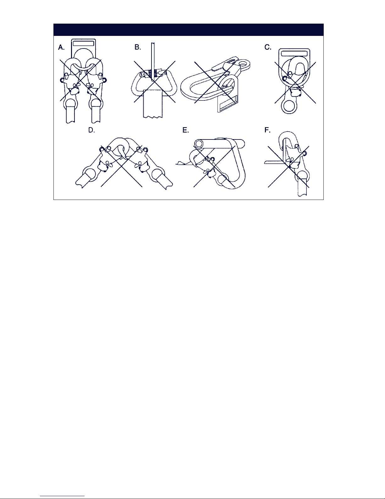
DBI/SALA connectors (snap hooks and carabiners) are designed to be
used only as specified in each product’s user’s instructions. See
Figure 4 for inappropriate connections. DBI/SALA snap hooks and
carabiners should not be connected:
A. T o a D-ring to which another connector is attached.
B. In a manner that would result in a load on the gate.
NOTE: Large throat opening snap hooks should not be connected to
standard size D-rings or similar objects which will result in a load on the gate
if the hook or D-ring twists or rotates. Large throat snap hooks are designed
for use on fixed structural elements such as rebar or cross members that are
not shaped in a way that can capture the gate of the hook.
C. In a false engagement, where features that protrude from the snap
hook or carabiner catch on the anchor and without visual
confirmation seems to be fully engaged to the anchor point.
D. To each other .
E. Directly to webbing or rope lanyard or tie-back (unless the
Figure 3 - Unintentional Disengagement (Roll-out)
If the connecting element that a snap hook (shown) or carabiner attaches to is
undersized or irregular in shape, a situation could occur where the connecting
element applies a force to the gate of the snap hook or carabiner. This force may
cause the gate (of either a self-locking or a non-locking snap hook) to open,
allowing the snap hook or carabiner to disengage from the connecting point.
1. Force is applied to
the snap hook.
2. The gate presses against
the connecting ring.
3. The gate opens
allowing the snap
hook to slip off.
Small ring or other
non-compatibly
shaped element
Page 7
8
manufacturer’s instructions for both the lanyard and connector
specifically allows such a connection).
F. To any object which is shaped or dimensioned such that the snap
hook or carabiner will not close and lock, or that roll-out could
occur.
2.4 STRUCTURAL STRENGTH: The structure (mounting surface) onto
which the tripod is erected (floor , tank top, roof, etc.) must meet
minimum strengths given below for the applications selected:
Fall Arrest: From ANSI Z359.1; “The structure (mounting surface)
selected for personal fall arrest systems (PF AS) shall have a strength
capable of sustaining static loads in the direction(s) permitted by the
PF AS when in use of at least (A) 3,600 lbs. (16kN) when certification
exists (see ANSI Z359.1 for certification definition), or (B) 5,000 lbs.
(22.2kN) in absence of certification. When more than one tripod is
installed on a structure for fall arrest, and the systems will be used
simultaneously , the strengths set forth in (A) and (B) above shall be
multiplied by the number of systems attached to the structure.” From
OSHA 1926.500 and 1910.66; “Anchorages (mounting surface) used
for attachment of personal fall arrest systems (PF AS) shall be
independent of any anchorage being used to support or suspend
platforms, and capable of supporting at least 5,000 lbs. (22.2kN) per
user attached, or be designed, installed, and used as part of a
complete PF AS which maintains a safety factor of at least two and is
under the supervision of a qualified person.”
Figure 4 - Inappropriate Connections
Page 8

9
Work Positioning: The structure (mounting surface) selected for work
positioning applications must sustain a static load of at least 5,000 lbs.
applied in the directions permitted by the work positioning system
when in use. Each tripod installation must independently sustain this
load.
Personnel Riding: The structure (mounting surface) selected for
personnel riding applications must sustain a static load of at least
2,500 lbs. applied in the directions permitted by the personnel riding
system when in use. Each tripod installation must independently
sustain this load.
Material Handling: The structure (mounting surface) selected for
material handling applications must sustain a static load of at least
2,500 lbs. applied in the directions permitted by the material handling
system when in use. Each tripod installation must independently
sustain this load.
Rescue: The structure (mounting surface) selected for rescue
applications must be capable of sustaining a static load of at least
2,500 lbs. applied in the directions permitted by the rescue system
when in use. Each tripod installation must independently sustain this
load.
3.0 OPERATION AND USE
WARNING: Do not alter or intentionally misuse this equipment. Consult
DBI/SALA when using this equipment in combination with components or
subsystems other than those described in this manual. Some subsystem and
component combinations may interfere with the operation of this equipment.
Use caution when using this equipment around moving machinery , electrical
hazards, chemical hazards, and sharp edges.
WARNING: Consult your doctor if there is reason to doubt your fitness to
safely absorb the shock from a fall arrest. Age and fitness seriously affect a
worker's ability to withstand falls. Pregnant women or minors must not use
the DBI/SALA tripods except for emergency situations.
3.1 BEFORE EACH USE: Before each use of this equipment carefully
inspect it to ensure that it is in good working condition. Check for worn
or damaged parts. Ensure all parts (nuts, bolts, etc.) are present and
secure. Check legs to ensure they are straight, free of cracks, dents,
etc. Ensure pulleys rotate freely and entire system is free of corrosion.
Refer to section 5.0 for further inspection details. Do not use if
inspection reveals an unsafe condition.
Page 9

10
3.2 PLANNING: Plan your work positioning, personnel riding, personal fall
arrest, material handling, or rescue and evacuation system before
starting your work. Consider all factors that affect your safety at any
time during use. Some important points to consider when planning
your system are:
A. HAZARD EV ALUA TION: An evaluation of job site hazards is
necessary prior to starting work. Consult applicable OSHA and
industry standards for guidelines and regulatory requirements on
issues such as confined space entry , personal fall arrest
systems, single point adjustable suspended scaffolds, etc.
B. WORK SITE GEOMETRY : The installation and use of the tripod
must be consistent with the geometric requirements given in
section 3.4 or 3.5. When suspending working lines from the tripod
check for obstructions or sharp edges in the work path. Avoid
working where the user may swing and hit an object or where lines
may cross or tangle with that of another worker in the area.
C. SECONDARY OR BACK-UP F ALL ARREST SYSTEM: When
using the tripod as a support for suspending a worker at a work
level, or for personnel riding applications, a secondary or back-up
fall arrest system is required. See OSHA 29 CFR 1910.28 and
1926.451. The tripod has provisions for connection of a secondary
or back-up personal fall arrest system. See sections 3.3 and 3.5.
D. RESCUE: In the event of an accident with injuries or other
medical emergency , it is critical that a means of dealing with such
a situation has been planned in advance. Response time often
plays an important role in the survival of an injured worker. Users
of this equipment must be trained in emergency procedures.
3.3 REQUIREMENTS FOR PERSONAL FALL ARREST SYSTEMS:
Personal fall arrest systems used with this tripod must meet
applicable OSHA requirements. When in use, the PFAS should be
rigged to minimize any potential free fall and never allow a free fall
greater than six feet. It is recommended that the PFAS used with this
equipment include a full body harness as the body support
component. PF AS's that incorporate full body harnesses must
maintain fall arrest forces below 1,800 lbs. and arrest the fall within 42
inches. Body belts, unless incorporated into a full body harness, not
recommended for use with this equipment. A typical PFAS includes a
full body harness, a connecting subsystem or component (self
retracting lifeline or a lifeline and rope grab) and the connectors to
couple the system together.
Page 10

11
WARNING: Follow the manufacturer's instructions for the personal fall arrest
equipment selected for use with the tripod.
IMPORTANT: For free fall and rescue applications, body belts are not
recommended for use. Body belts increase the risk of injury during fall arrest
in comparison to a full body harness and drastically reduce the tolerable
suspension time compared to a full body harness. Limited suspension time,
increased risk of injury , and the potential for improperly wearing a body belt,
may result in added danger to the user. DBI/SALA recommends using a full
body harness for fall arrest and rescue applications.
3.4 INSTALLA TION REQUIREMENTS OF TRIPOD
A. LOAD REQUIREMENTS: Depending on the application, the
strength requirements for the supporting structure onto which the
tripod is erected vary . See section 2.4 for application types and
the supporting structure load requirements. If an installation will be
used for more than one type of application, always select the
loading for the application with the greater load requirements.
B. GEOMETRIC REQUIREMENTS: The tripod must be mounted
where it can be leveled using the leg adjustments. The footing
must be solid under each leg, and support the intended loading.
Position the tripod such that the lifeline will be directly over the
intended work area when installed. Do not position the tripod
where the worker will have to swing under the tripod to reach the
work area. Avoid positioning the tripod where the working line may
abrade against sharp edges. See Figure 5.
W ARNING: Never allow the working line to extend outside the legs of the
tripod. Tipping of the tripod could occur.
C. TO ERECT TRIPOD: The tripod is shipped with the legs set at full
retraction. Erect as follows, see Figure 5: 1) Lay the tripod on the
working surface; 2) Adjust legs to required working height; 3) T ilt
the tripod into an upright position; 4) Fully spread the legs, ensure
legs are against bearing surface on head. The legs will
automatically lock in place. To collapse tripod, pull leg down to
disengage leg lock and swing leg in; 5) Position tripod over
opening so working line will be located approximately in the center
of the opening. Ensure footing is solid under each leg and can
support the intended loads. Level the tripod by adjusting the leg
height; 6) Adjust the leg chain by removing excess slack.
WARNING: Except for emergency situations where leg chains may interfere
with rescue, the tripod must never be used without the leg chains in place.
Page 11

12
Figure 5
Page 12

13
Figure 6
Figure 7
IMPORTANT : The tripod must be positioned so the working line will be
directly over the intended work area. It must be positioned to ensu re a safe
working area for the operator.
WARNING: Do not use the tripod if one or more of the legs are not locked
into the erect position (completely spread out).
3.5 CONNECTING EQUIPMENT TO THE TRIPOD: The tripod has been
designed for multi-purpose applications that may involve the use of
one or more systems attached to the tripod. The following details the
connection of equipment to DBI/SALA tripods. See associated
equipment instructions for further information:
A. EYE-BOLT: A component (self
retracting lifeline, rope grab/
lifeline system) can be
attached to either one of the
eye-bolt anchorage points.
See Figure 6. Connect
equipment to the eye bolt
anchorage point by using a
clevis and pin (minimum
breaking strength of 5,000
lbs.), self locking carabiners or
self locking snap hooks.
B. LEG MOUNT PULLEY :
Figures 7 and 8 shows the
optional leg mount pulley model 8003238. This pulley is used
when more than one device is mounted to the tripod leg requiring a
directional pulley. The leg mount pulley will accommodate up to 1/4
inch diameter line. Install the leg mount pulley on the desired
tripod leg as shown in Figure 7. Position the leg mount pulley
directly under the leg lock
near the top of the tripod.
The pulley may be
positioned on either side
of the tripod leg. It may be
necessary to remove one
of the eye bolts to gain
clearance for the lifeline.
Tighten the clamp plate
bolts to 15 ft.-lbs. Do not
use or install more than
one system on a single
tripod leg.
Page 13

14
C. QUICK-MOUNT BRACKET : Figure 8 shows the tripod quick-mount
leg bracket 8005048 (optional on 8001717 and 8001718 models).
To install the quick-mount bracket to the tripod leg, assemble as
shown in Figure 8. Adjust bracket to desired position on the leg
and tighten bolts to 15 ft.-lbs. Do not over tighten. Do not install
quick-mount bracket onto the lower (telescoping) leg. The quickmount bracket must be used for connection of the Salalift® winch
(8101000 series), the Work Winch (8103000 series) and for leg
mounting of DBI/SALA Self Retracting Lifelines.
D. HEAD MOUNT PULLEYS: The 8000000 and 8000010 model
tripods come equipped with head mounted pulleys. These pulleys
should be used for mounting the line of the primary use system
over the tripod head when used in the leg mounted position. The
head mount pulleys will accommodate up to a 1/4 inch diameter
line. See Figure 8, 9, and 10.
E. SNA TCH BLOCK PULLEY : Figures 8 and 10 show the optional
snatch block pulley assembly model 8003205. The snatch block is
used when more than one device is mounted to the tripod
requiring a directional pulley . The snatch block is attached to one
of the unused eye-bolts and will accommodate up to 1/4 inch
diameter line. Do not use the Salalift winch with the snatch block
Figure 8
Page 14

15
pulley because of possible cable rubbing on the tripod leg, and
uneven winding of the cable onto the winch drum.
F . SALALIFT® WINCH: When using the Salalift winch (8101000
series) with the tripod, the winch must be mounted to the leg
in-line with the head mount pulleys. Route the winch line over the
head mount pulleys as instructed in the Salalift® winch user
instruction manual. Do not use winch with snatch block pulley
(see section 3.5.E).
WARNING: Multiple systems may be attached to the tripod (primary support
lifeline and back-up lifeline), but the tripod is for one person use only .
Exception: Emergency rescue applications only . A maximum of one system
can be attached to any one tripod leg. A maximum of two systems should be
attached to one tripod, except back-up lifelines (fall arrest) which are limited
to one system.
IMPORTANT: Knots must not be used for load-bearing end terminations
(see ANSI Z359.1). Some knots reduce the strength of the lifeline by 50
percent or more.
4.0 TRAINING
4.1 It is the responsibility of the user to assure they are familiar with these
instructions, and are trained in the correct care and use of this
equipment. User must also be aware of the operating characteristics,
application limits, and the consequences of improper use of this
equipment.
IMPORTANT: T raining must be conducted without exposing the trainee to a
fall hazard. T raining should be repeated on a periodic basis.
5.0 INSPECTION
5.1 FREQUENCY:
• Before Each Use: Visually inspect per steps listed in sections 5.2
and 5.3.
• Monthly: A formal inspection of the tripod should be done by a
competent person other than the user. See sections 5.2 and 5.3 for
guidelines. Record results in the inspection and maintenance log in
section 9.0.
• After Fall Arrest: Inspect entire tripod and base per section 5.2.
Page 15

16
Figure 9
T wo Salalift® Winches Mounted to T ripod
Lifelines routed through Head Mount Pulley and Leg Mount Pulley
Page 16

17
Figure 10
Salalift® Winch and Self Retracting Lifeline Mounted to T ripod
Lifelines routed through Head Mount Pulley and Snatch Block Pulley
Page 17

18
WARNING: If the tripod has been subjected to fall arrest or impact forces, it
must be immediately removed from service and inspected. If the tripod fails
to pass the inspection, do not use; the equipment must be destroyed or sent
to DBI/SALA for possible repair .
IMPORTANT: Extreme working conditions (harsh environment, prolonged
use, etc.) may require increasing the frequency of inspections.
5.2 INSPECTION STEPS FOR TRIPOD
Step 1. All bolts and nuts must be securely attached. Check for
missing, altered, or substituted bolts, nuts, locking detent
pins or other parts. Inspect the tripod for signs of corrosion
which may weaken or affect parts in their function.
Step 2. Check each leg to see that it can be telescoped in and out
freely . Inspect legs for straightness. Ensure legs lock into
place when tripod is erect.
Step 3. Check the feet on each leg; ensure they pivot and the rubber
pad is in place.
Step 4. Check leg chain and connections; Ensure they are tight and
undamaged, chain must be free of defects and hook must be
in place and work properly .
Step 5. Check the head. Ensure the eye-bolt anchorage points are in
place and are free from damage. Ensure the cable pulleys are
clean and rotate freely (8000000 and 8000010 models only).
Step 6. Inspect the labels. Ensure all labels are present and fully
legible. See section 8.0.
Step 7. Record the results of inspection in the inspection and
maintenance log in section 9.0 of this manual.
Step 8. Inspect each system component according to manufacturer's
instructions.
5.3 If inspection or operation reveals a defective condition, remove the
tripod from service immediately and contact an authorized service
center for repair .
NOTE: Only DBI/SALA or parties authorized in writing may make repairs to
this equipment.
Page 18

19
ledoMthgieWdaoLgnikroWdetaRlairetaM
7171008.sbl73
krowrof.sbl053
lennosreprogninoitisop
,snoitacilppagnidir
tserrallafrof.sbl013
snoitacilppa
yltnanimoderP
cnizdnamunimula
leetsdetalp
8171008.sbl64
0000008.sbl74
0100008.sbl65
6.0 MAINTENANCE, SERVICING, STORAGE
6.1 Periodically clean the exterior of the tripod using water and a mild
detergent solution. Clean labels as required.
6.2 Replacement parts and additional maintenance and servicing
procedures must be completed by a factory authorized service center.
An authorization and a return number must be issued by DBI/SALA.
6.3 Clean and store the body support and associated system components
according to separate instructions provided with that equipment.
6.4 Store this equipment in a cool, dry , clean environment out of direct
sunlight. Avoid areas where chemical vapors may exist. Inspect after
any period of extended storage.
7.0 SPECIFICATIONS
See Figure 11.
snoisnemiD
)11erugiFees(
sledoM.tf7sledoM.tf9
muminiM
thgieH
)mm(hcni
mumixaM
thgieH
)mm(hcni
muminiM
thgieH
)mm(hcni
thgieHmumixaM
)mm(hcni
htgneLegarotS)877,1(07----)195,2(201----
retemaideloH*
dennaps "A"
)485(32)318(23)838(33)811,1(44
thgiehllarevO "B" )727,1(86)263,2(39)314,2(59)840,3(021
thgiehtfilelbaliavA
"C"
)542,1(94)088,1(47)039,1(67)565,2(101
stnemercnithgieH)67(3----)67(3----
sgelfodaerpS "D"
eohsfoedisnI
)811,1(44)006,1(36)156,1(56)431,2(48
sgelfodaerpS "E"
eohsfoedistuO
)374,1(85)659,1(77)700,2(97)515,2(99
Page 19

20
* Note: Tripods will span a larger opening; the leg chains will cross
over a portion of the opening.
• These tripods meet ANSI Z359.1, ANSI A10.14, and OSHA
requirements.
• The 8000000 and 8000010 are U.L. classified. See product label for
details.
8.0 LABELING
8.1 The following labels must be present and fully legible:
Warning Label
Models 8001717
and 8001718
Specification Label
Models 8001717 and
8001718
Overtighten
Label Model
1001190
Warning Label
Models 8000000
and 8000010
Specification
Label Models
8000000 and
8000010
Page 20

21
Figure 11
Geometric Requirements
Page 21

22
NOITCEPSNI
ETAD
NOITCEPSNI
DETONSMETI
EVITCERROC
NOITCA
ECNANETNIAM
DEMROFREP
:yBdevorppA
:yBdevorppA
:yBdevorppA
:yBdevorppA
:yBdevorppA
:yBdevorppA
:yBdevorppA
:yBdevorppA
:yBdevorppA
:yBdevorppA
:yBdevorppA
9.0 INSPECION AND MAINTENANCE LOG
SERIAL NUMBER: _______________________________________________
MODEL NUMBER: _______________________________________________
DA TE PURCHASED: _____________________________________________
Page 22

Page 23

I S O
9 0 0 1
Certificate No. FM 39709
From: 5902140
Rev : G
Capital Safety
3833 SALA Way
Red Wing, MN 55066-1837
Distributed by Engineered Fall Protection
Email: sales@engineeredfallprotection.com
Web: www.engineeredfallprotection.com
PH: 314-492-4422 | FAX: 800-570-5584
W ARRANTY
Equipment offered by DBI/SALA is warranted against factory defects in
workmanship and materials for a period of two years from date of installation
or use by the owner , provided that this period shall not exceed two years
from date of shipment. Upon notice in writing, DBI/SALA will promptly
repair or replace all defective items. DBI/SALA reserves the right to elect
to have any defective item returned to its plant for inspection before making
a repair or replacement. This warranty does not cover equipment damages
resulting from abuse, damage in transit, or other damage beyond the control
of DBI/SALA. This warranty applies only to the original purchaser and is
the only one applicable to our products, and is in lieu of all other warranties,
expressed or implied.
 Loading...