

Page 1
Rollgliss
®
R550 Rescue & Escape Device
Model Numbers: (See back pages.)
The Ultimate in Fall Protection
USER INSTRUCTION MANUAL
ROLLGLISS® R550 RESCUE & ESCAPE DEVICE
This manual is intended to meet the Manufacturer’s Instructions as required by ANSI/ASSE Z359.4 and
CSA Z259.2.3. It should be used as part of an employee training program as required by OSHA.
WARNING: This product is part of an emergency rescue system. The user must follow manufacturer’s instructions for each
part of the system. These instructions must be provided to the user of this equipment. The user must read and understand
these instructions before using this equipment. Manufacturer’s instructions must be followed for proper use and maintenance
of this equipment. Alterations or misuse of this equipment, or failure to follow instructions, may result in serious injury or
death.
IMPORTANT: If you have questions on the use, care, or suitability of this equipment for your application, contact Capital
Safety.
IMPORTANT: Record the product identication information from the ID label in the inspection and maintenance log in
Section 9 of this manual.
DESCRIPTION:
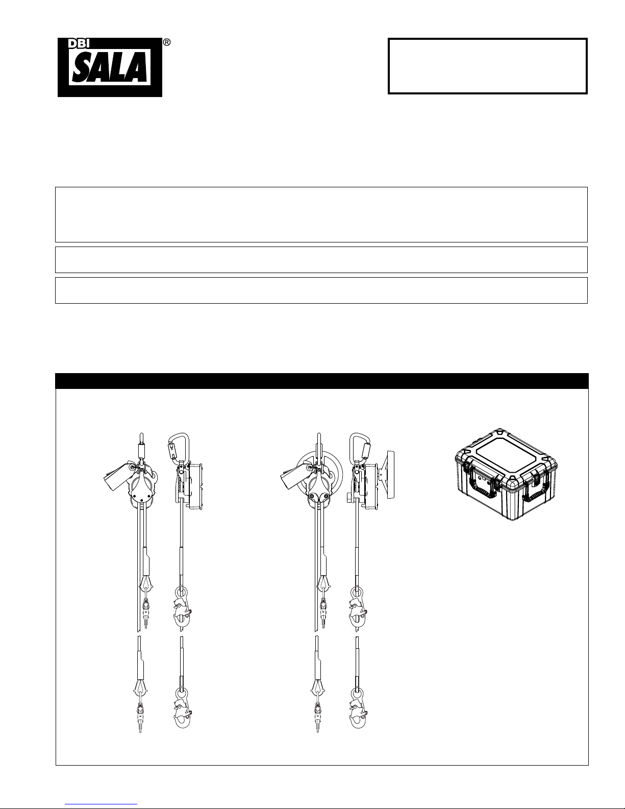
The R550 Rescue & Escape Device (Figure 1) is available in Descent with Rescue Lifting or Descent Only models.
A Humidity Resistant Case combination to protect the R550 Descender against environmental conditions is
available on some models. An integral bracket is available as an accessory that will attach the R550 to a ladder.
Rollgliss R550
Models: 3325XXX
Figure 1 - R550 Rescue & Escape Devices
Rollgliss R550 with Rescue Lifting
Models: 3327XXX
Humidity Resistant Case
Models: 3326XXX
Available descent lengths range from 50 ft. (15 m) to 1,640 ft. (500 m) in 25 ft. (8 m) increments. The last three digits of the Model Number (signied
by ‘XXX’) indicate the maximum descent length in feet.
Form: 5903520 Rev: C
© Copyright 2013, DB Industries, Inc.
Page 2
1.0 APPLICATION
1.1 PURPOSE: The R550 Rescue & Escape Device is intended to lower one or two people simultaneously from
an elevated height to a lower level in a rescue situation. Multiple people may descend one after another
using the device. The descent speed is automatically limited during descent. Models incorporating a hand
wheel allow for raising persons a short distance to facilitate rescue.
WARNING: The R550 Rescue & Escape Device is for Rescue purposes only. It must not be used as a fall arrest device.
1.2 LIMITATIONS: The following application limitations must be recognized and considered before using this product:
A. CAPACITY: Required capacities and descent distances for the Rollgliss R550 are as follows:
Users
2 Persons 130 lbs (59 kg) - 620 lbs (282 kg) 574 ft. (175 m) 2
1 Person 130 lbs (59 kg) - 310 lbs (141 kg) 1,640 ft. (500 m) 11
1 Person 130 lbs (59 kg) - 220 lbs (100 kg) 1,640 ft. (500 m) 16
1 Person 130 lbs (59 kg) - 165 lbs (75 kg) 1,640 ft. (500 m) 22
Total Weight
(including tools, clothing, etc.)
Max. Descent Distance
Number of Descents of
Max. Descent Distance
B. MAXIMUM DESCENT DISTANCE AND MAXIMUM NUMBER OF DESCENTS: See Section 10.0
Descent Log for instructions to calculate the allowed Maximum Cumulative Descent Distance.
C. DESCENT SPEED: The speed at which the user(s) will be lowered when using the Rollgliss R550 Rescue
& Escape Device increases with the combined weight of the user(s). The approximate descent speed for
one person is 2-3 ft/s (0.6 - 0.9 m/s). The approximate descent speed for two persons is 2 ft/s - 4 ft/s
(0.6 m/s - 1.2 m/s).
D. HAZARDOUS AREAS: Use of this equipment in hazardous areas may require additional precautions to
reduce the possibility of injury to the user or damage to the equipment. Hazards may include, but are
not limited to: high heat, caustic chemicals, corrosive environments, high voltage power lines, explosive
or toxic gases, moving machinery, and sharp edges.
E. TRAINING: This equipment is intended to be installed and used by persons trained in its correct
application and use.
1.3 APPLICABLE STANDARDS: Refer to ANSI/ASSE Z359.1, Z359.4, CSA Z259.2.3 and other applicable local,
state, and federal (OSHA) standards for requirements governing the use of this equipment.
2.0 SYSTEM REQUIREMENTS
2.1 COMPATIBILITY OF COMPONENTS: DBI-SALA equipment is designed for use with DBI-SALA approved
components and subsystems only. Substitutions or replacements made with non-approved components or subsystems
may jeopardize compatibility of equipment and may effect the safety and reliability of the complete system.
2.2 COMPATIBILITY OF CONNECTORS: Connectors (hooks, carabiners, D-rings) used to suspend the
R550 Rescue & Escape Devices must be capable of supporting at least 3,000 lbs (1,361 kg). Connectors
must be compatible in size, shape, and strength. Non compatible connectors may unintentionally disengage
(roll-out). Roll-out occurs when interference between the connector and anchorage connector causes the
hook or carabiner gate to unintentionally open and release. Self locking snap hooks and carabiners must be
used with this system to reduce the possibility of roll-out. Do not use connectors that will not completely
close over the attachment element.
2.3 ANCHORAGE STRENGTH - R550 RESCUE & ESCAPE DEVICE: Anchorages used to suspend the
R550 Rescue & Escape Device must sustain static loads, applied along the axis of the device, of at least
3,000 lbs (1,361 kg). When more than one R550 Descender is attached to an anchorage the strengths
stated above must be multiplied by the number of descent devices attached to the anchorage.
3.0 INSTALLATION AND USE
3.1 BEFORE EACH USE: Carefully inspect the R550 Rescue & Escape Device in accordance with Section 5 of
this instruction.
3.2 PLANNING: Plan your emergency escape system and how it will be used before starting your work.
Consider all factors that will affect your safety before, during, and after an escape. Consider the following
when planning your system:
A. ANCHORAGE: Select a rigid anchorage point that is capable of supporting the load as specified by
Section 2.3 in this instruction.
2
Page 3
B. DESCENT PATH AND LANDING AREA CLEARANCE: The planned descent path must be unobstructed.
The landing area must be clear of obstructions to permit safe landing of the user. Failure to provide an
unobstructed descent path and landing area may result in serious injury. Maintain a minimum distance of 1
foot (31 cm) from any vertical surface to ensure safe descent. A separate pulley is available for use with the
R550 Rescue & Escape Device that can be used to re-direct the lifeline away from obstructions.
C. TESTING THE SYSTEM: DBI-SALA recommends performing a test descent using a 120 lb (55 kg)
test weight. The descent speed should be uniform, and allow the user to reach the landing area safely.
Record all descents in the Descent Log (Section 10).
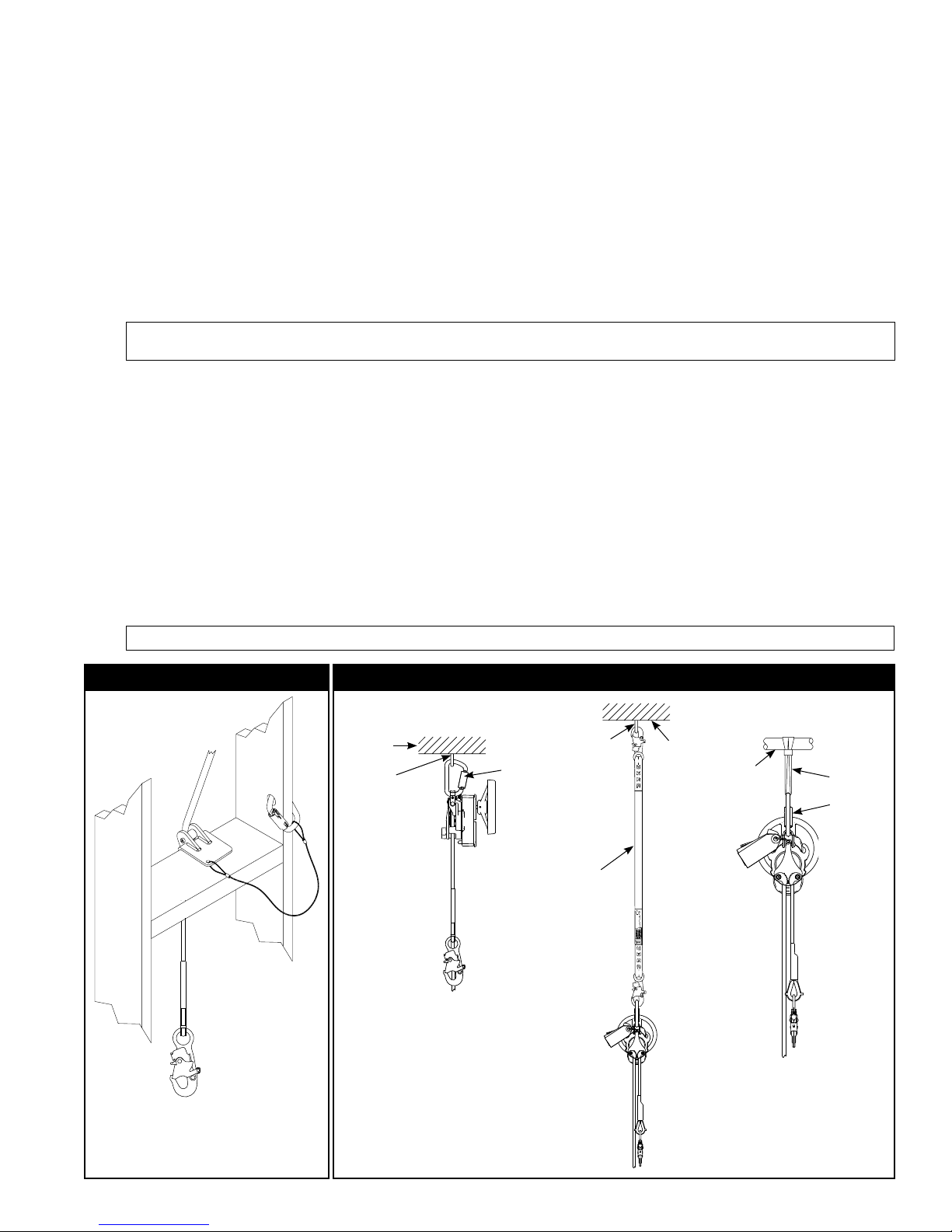
D. SHARP EDGES: Avoid using this equipment where system components will be in contact with, or abrade
against, unprotected sharp edges. An Edge Protector (Figure 2) or protective padding must be used
when descending over sharp edges.
3.3 INSTALLATION: The R550 Rescue & Escape Device is available in several congurations and therefore its
installation will vary.
WARNING: When connecting the R550 Descender to an Anchorage, conrm that the connection arrangement will not
block or restrict a descent.
CONNECTING THE R550 DESCENDER TO ANCHORAGE: Figure 3 illustrates attachment of the
Emergency Descent Device to an anchorage. See Section 2 for compatibility and anchorage strength
requirements.
• Connecting the R550 Descender to a Fixed Ladder: The R550 can be attached to the rungs of a
xed ladder with a DBI-SALA ladder bracket accessory (see Figure 4). The R550 Descender mounts on
the Ladder Bracket by tting the lower eye of the R550 over the pin on the ladder bracket and inserting
the Ball Lock Pin through mounting holes in the R550 anchor loop and ladder bracket. R550 Descenders
mounted with the ladder bracket still require that the unit be secured by the anchorage handle to an
anchorage of sufcient strength (see Section 2.3).
• Preparing the Lifeline: Lower one end of the lifeline to the ground or landing below. Ensure the lifeline
is free of knots or kinks.
3.4 USE - SINGLE PERSON UNASSISTED ESCAPE: Procedures for performing and unassisted descent with
the R550 Rescue & Escape Device are as follows:
WARNING: The users of this equipment must be in good physical condition. The user must have the ability to absorb the landing.
Figure 2 - Edge Protector Figure 3 - Connecting the R550 Descender to Anchorage
Anchorage
Anchorage
Connector
Carabiner
Anchorage
Connector
Web
Lanyard
Anchorage
Anchorage
Anchorage
Connector
(Web Sling)
Carabiner
3
Page 4

Figure 4 - Connecting the R550 Descender
to a Ladder
Anchorage
Anchorage Connector
(Web Sling)
Figure 5 - Connecting to a Full Body
Harness
Back
D-Ring
Ladder Bracket
Carabiner
Ball Lock Pin
Fixed Ladder
Ladder Rungs
Front
D-Ring
Step 1. Connect to a Full Body Harness
or other Body Support: A full body
harness or other means of supporting
the user must be used with the
R550 Descender. Do not use a body
belt with this device. When using a
full body harness, connect the Snap
Hook on the lifeline to the front or
back D-ring (Figure 5). Ensure the
D-ring is positioned to hold the user
upright. See the full body harness
manufacturer’s instructions for more
information.
WARNING: Do not use a body belt with this equipment. Body belts do not support your entire body,
which may result in serious injury.
Step 2. Prepare the Lifeline for Descent: Prior to descent, the section of lifeline between the user and
the R550 Descender must be tightened to remove any slack. Tighten the lifeline by pulling on
the free end of the rope until slack between the user and R550 Descender is removed. Once the
lifeline is taut, hold the free end of the lifeline tightly until descent is initiated.
Step 3. Descend to Safety: Release the free end of the lifeline to initiate descent. Descent speed will be
automatically controlled to a rate described in Section 1.2 C by the R550 Descender’s centrifugal
brake. Descent may be interrupted by rmly grasping the free end of the lifeline (see Figure 6).
Bend your knees to prepare for landing. After landing, disconnect the lifeline from the body
support.
NOTE: Always wear gloves when handling the lifeline to control descent speed.
CAUTION: The R550 Rescue & Escape Device may become hot during use which could injure the user if
parts other than those used to control the descent are touched. Use beyond the specied load and descent
length limits may generate excessive heat which could damage the descent line.
Step 4. Prepare for the Next Descent: After use of the R550 Rescue & Escape Device, the lifeline must
be pulled through the device as needed to position a lifeline end and Snap Hook adjacent to the
next person to descend.
3.5 USE - ASSISTED RESCUE: The R550 Rescue & Escape Device is equipped with a Rescue Hub which can be used in
remote assisted rescues to raise the fall victim to permit removal of their fall arrest subsystem (lanyard, etc.) prior to
descent to safety (see Figure 7). Procedures are as follows:
Step 1. Lower or Raise One End of the Lifeline to the Victim: Pull the lifeline through the
R550 Descender as needed until the Snap Hook on one end of the rope is adjacent to the desired
connection point on the victim’s body support.
NOTE: In the event the connection point on the victim’s body support is not within reach, the Rope Grab accessory
can be attached upside down (ò) on the victim’s lanyard and locked in place (see Figure 7). The Snap Hook on the
R550 lifeline can be attached to the Eye on the Rope Grab and the Rescue Hub used to raise the victim to safety, or a
point where their initial fall protection system can be released to allow lowering the victim to safety.
4
Page 5
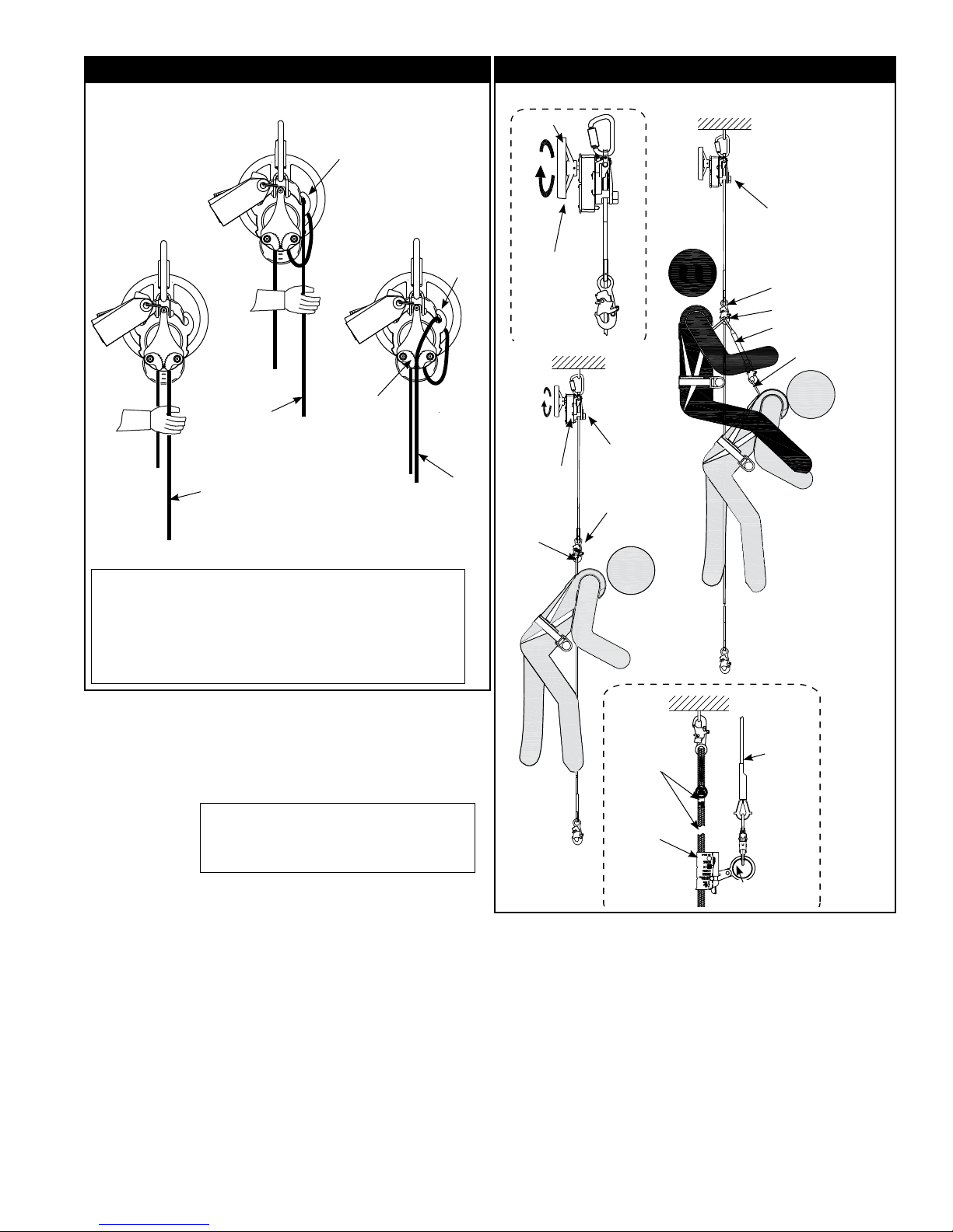
Figure 6 - Descent Control Figure 7 - Rescue Applications
For additional
descent control:
Lifting Handle
Pigtail
Simultaneous
Rescue/Escape
To slow or
interrupt
descent:
Free
End
Free
End
To suspend descent
and hold the victim
during rescue:
Pigtail
Cam
Cleats
NOTE: Descent may be interrupted by rmly grasping
the free end of the rope. For additional leverage, the
free end of the rope can be passed through the Pigtail
and then grasped. To suspend descent for longer
durations and free both hands for rescue, the free end of
the rope should be passed through the Pigtail and then
secured in the Cam Cleats.
Free
End
Rescue
Hub
Remote Assisted Rescue
Rollgliss
Rescue
Hub
Harness
D-Ring
R550
Rescue End
Snap Hook
Rollgliss
R550
Rescue End
Snap Hook
Harness D-Ring
Harness
D-Ring
Rescue Lanyard
Step 2. Connect to the Victim’s Full Body
Harness or other Body Support:
Connect the Snap Hook on the Rescue
End of the lifeline to the front or back
D-ring (Figure 5). Ensure the D-ring is
positioned to hold the user upright.
Victim’s
Lanyard
R550
Lifeline
WARNING: Do not use a body belt
with this equipment. Body belts do not
support the entire body, which may
result in serious injury.
Rope
Grab
Eye
Step 3. Raise the Victim to Disconnect the Fall Arrest Subsystem: Rotate the Rescue Hub to raise
the victim’s weight from the fall arrest subsystem and onto the R550 Rescue & Escape Device.
Secure the Free End of the lifeline with the R550 Descender’s Pigtail and Cam Cleats to prevent
unintentional descent (see Figure 6). Disconnect the Victim’s fall arrest subsystem (Lanyard,
etc.).
5
Page 6

Alternate Option: The R550 Rescue & Escape Device
Figure 8 - Power Drill Assist
is also congured to allow a Power Drill (minimum 1/2”
chuck and 400 lbf-in torque) to be attached to the
center of the Rescue Hub which can be used in remote
assisted rescues to raise the fall victim. (See Table 1
on this page for an example of lifting distances.) Attach
the Power Drill directly to the shaft at the center of the
Rescue Hub (see Figure 8). Use the attached Power
Drill to rotate the Rescue Hub to raise the victim’s
weight from the fall arrest subsystem and onto the
R550 Rescue & Escape Device. Secure the Free End of
the lifeline with the R550 Rescue and Escape Device’s
Pigtail and Cam Cleats to prevent unintentional descent
(see Figure 6). Detach the Power Drill by lowering the
victim’s weight onto the unit’s Pigtail and Cam Cleats
and then releasing the Power Drill from the center of
the Rescue Hub. Once the Powered Drill is removed,
disconnect the Victim’s fall arrest subsystem (Lanyard,
etc.)
Table 1: Single Battery Lifting Distances in either direction for DeWalt 20V Drill (Model DCD990M2)
Low Speed Medium Speed High Speed
220 lb (100 kg) Load 250 ft (76 m)* 250 ft (76 m)* 175 ft (53 m)*
310 lb (141 kg) Load 200 ft (61 m)* 150 ft (46 m)* NA**
* Lifting distance based on full battery charge, ambient temperature of 72° F (22° C).
** High speeds with high loads not recommended.
NOTE: Power Drill lifting capabilities will vary with victim load, battery charge, drill model, and
environmental conditions. The lowest drill speed setting is recommended to maximize battery life and to
reduce the risk of damaging the drill or the R550 Descender. Loads greater than 310 lbs (141 kg) should
not be lifted with the Power Drill option. Lifting in reverse direction will typically decrease the lifting distance
capacity of a single battery charge.
Step 4. Prepare the Lifeline for Descent: Prior to descent, the section of lifeline between the user and
the R550 Descender must be tightened to remove any slack. Tighten the lifeline by pulling on the
free end of the lifeline until slack between the user and R550 Descender is removed. Once the
lifeline is taut, hold the free end of the lifeline tightly until descent is initiated.
Step 5. Descend to Safety: Release the free end of the lifeline to initiate descent. Descent speed will be
automatically controlled to a rate described in Section 1.2 C by the R550 Descender’s centrifugal
brake. Descent may be interrupted by rmly grasping the free end of the lifeline (see Figure 6).
Bend your knees to prepare for landing. After landing, disconnect the lifeline from the body
support. Record all descents in the Descent Log (Section 10).
CAUTION: The R550 Rescue & Escape Device may become hot during use which could injure the user if parts other
than those used to control the descent are touched. Use beyond the specied load and descent length limits may
generate excessive heat which could damage the descent line.
3.6 USE - SIMULTANEOUS RESCUE/ESCAPE: In situations where the fall victim requires assistance,
simultaneous rescue/escape allows a rescuer1 to accompany the victim during descent (see Figure 7):
WARNING: Two person descents with the R550 Rescue & Escape Device should not exceed a total combined weight
(including tools, clothing, body support, etc.) of 620 lbs (282 kg) and a descent distance of 574 ft. (175 m).
Step 1. Descend to the Victim: In situations where the fall victim is suspended by their existing Fall
Arrest subsystem, it will be necessary for the rescuer to descend to the victim’s location to
provide assistance. Descend to the victim per the steps in Section 3.4.
IMPORTANT: When the victims position is reached, descent can be interrupted by rmly grasping and
holding the free end of the rope (See Figure 6). If a secondary rescuer is available at the R550 Descender,
the free end of the rope can be passed through the Pigtail and then secured in the Cam Cleats to prevent
unintentional descent while the primary rescuer is securing the victim.
Step 2. Connect the Victim to the R550 Rescue & Escape Device: Connect a Rescue Lanyard (or
similar equipment) between the Lifeline Snap Hook connected to the Rescuer’s Full Body Harness
Front D-Ring or the Back D-Ring on the Victim’s Full Body Harness (Figure 7).
WARNING: Do not use a body belt with this equipment. Body belts do not support your entire body,
which may result in serious injury.
1 Rescuer: Person or persons other than the rescue subject acting to perform an assisted rescue by operation of a rescue
system.
6
Page 7

Step 3. Disconnect the Victim’s Fall Arrest Subsystem: Ensure that the victim is securely attached
to the R550 Rescue & Escape Device and then detach the victim’s fall arrest subsystem (lanyard,
etc.) to free the victim for descent.
NOTE: If a secondary rescuer is available at the R550 Descender, the Rescue Hub and Lifting Wheel can be
used to raise the victim slightly for detachment of their fall arrest subsystem.
Step 4. Descend to Safety: Release the free end of the lifeline to initiate descent. Descent speed will be
automatically controlled to a rate described in Section 1.2 C by the R550 Descender’s centrifugal
brake. Descent may be interrupted by rmly grasping the free end of the lifeline (see Figure 6).
Bend your knees to prepare for landing. After landing, disconnect the lifeline from the body support.
Record all descents in the Descent Log (Section 10).
CAUTION: The R550 Rescue & Escape Device may become hot during use which could injure the user if parts other
than those used to control the descent are touched. Use beyond the specied load and descent length limits may
generate excessive heat which could damage the descent line.
4.0 TRAINING
It is the responsibility of the user and purchaser of this equipment to be trained in the correct care and use
of this equipment. The user and purchaser must be aware of the operating characteristics, application limits,
and consequences of improper use of this equipment.
WARNING: Training must be conducted without exposing the trainee to a fall hazard. Training should be repeated on a periodic basis.
5.0 INSPECTION
To ensure safe, efcient operation, the R550 Rescue & Escape Device should be inspected at intervals
dened in Section 5.1. See Section 5.3 for inspection procedures.
5.1 FREQUENCY: In addition to inspecting the R550 Rescue & Escape Device prior to each use, Inspection
should be performed at the following regular intervals:
• Pre-Use Inspection: If the Rollgliss R550 Rescue & Escape Device is not stored in a Humidity Resistant
Case (see Figure 9), the Rollgliss R550 Rescue & Escape Device should be inspected per the steps in
Section 5.3 prior to each use:
HUMIDITY RESISTANT CASE INSPECTION: If the R550 Rescue & Escape Device is stored continuously in a
Humidity Resistant Case (see Figure 10), monthly and yearly inspections are not required. In addition to inspection
prior to each use (see Section 5.3), the Humidity Indicator on the case (see Figure 10) should be inspected annually
and the date and inspector’s initials logged on the Case Inspection Label (see Section 8). If the Humidity Indicator
displays a reading of 60 or greater (Pie Sector Indicator), the case should be removed from service and the contents
inspected per the Inspection Steps dened in Section 5.3.
• At Least Annually: A formal inspection should be completed by a competent person2 other than the
user. A formal inspection should be completed if the system parameters are changed, such as after a
system is moved, Re-rigged, anchorages moved, etc. Extreme working conditions may require increasing
the Inspection frequency. Inspect the R550 Rescue & Escape Device in accordance with Section 5.3
and Section 5.4. Record inspection results in the Inspection and Maintenance Log, or use the i-Safe™
inspection web portal to maintain inspection records (see Section 5.2).
• Every Five Years: The R550 Rescue & Escape Device must be sent to an authorized service center for
inspection and service (see Section 6.2).
IMPORTANT: If the R550 Rescue & Escape Device is continuously stored in a Humidity Resistant Case (see
Figure 10) and pre-use and annual inspections of the case’s Humidity Indicator conrm allowable humidity levels,
the device must be sent to a authorized service center for inspection and service at intervals not to exceed ten
years. (See Section 6.2)
5.2 I-SAFE™ RFID TAG: R550 Rescue & Escape Devices are equipped with an i-Safe™ Radio Frequency
Identication (RFID) tag (Figure 9). The i-Safe™ RFID tag on the R550 Descender can be used in
conjunction with the i-Safe handheld reading device and the web based portal to simplify inspection and
inventory control and provide records for fall protection equipment. If you are a rst-time user, contact a
Customer Service representative in the US at 800-328-6146 or in Canada at 800-387-7484. If you have
already registered, go to: www.capitalsafety.com/isafe. Follow the instructions provided with the i-Safe
handheld reader or on the web portal to transfer your data to the web log.
2 Competent Person: Person who is knowledgeable of the current periodic examination requirements, recommendations and
instructions issued by the manufacturer applicable to the relevant component, subsystem or system.
7
Page 8

5.3 INSPECTION STEPS: Per the intervals dened in Section 5.1, inspect the R550 Descender as follows:
Step 1. (See Figure 10) If the R550 Rescue & Escape Device is stored in a Humidity Resistant Case, inspect the
Humidity Indicator on the outside of the case (A). If the Humidity Indicator displays a reading of 60 or
greater (pie sector indicator): (1) Open the case and inspect the R550 Descender per the remaining steps.
(2) Maintain the case as described in Section 6.1.
Step 2. Inspect device for loose fasteners and bent or damaged parts.
Step 3. Inspect device housing for distortion, cracks, or other damage. Ensure the anchorage handle is
not damaged or distorted.
Step 4. The lifeline must pull through the device. Inspect the entire rope for cuts, burns, severely abraded
areas, and excessive wear.
NOTE: The rope sheath may become frayed during normal use.
Step 5. Device labels must be present and fully legible (see Section 8).
Step 6. Inspect for corrosion on the device.
Step 7. Inspect carabiners for damage, corrosion, and working condition.
Step 8. Inspect all system components and subsystems according to manufacturer’s instructions.
Step 9. Record inspection results in the Inspection and Maintenance Log (Section 9) or on the i-Safe web
portal (Section 5.2).
5.4 UNSAFE OR DEFECTIVE CONDITIONS: If inspection reveals an unsafe or defective condition, remove the
device from service and contact an authorized service center for repair.
Figure 9 - i-Safe™ RFID Tag Figure 10 - Humidity Resistant Case (9508289)
Pie Sector
Indicator Disk
Humidity
Indicator
8
Page 9

6.0 MAINTENANCE, SERVICE, STORAGE
6.1 MAINTENANCE:
• Rollgliss R550 Descender: Periodically clean the exterior of the R550 Rescue & Escape Device with
water and mild detergent. Position the device so excess water will drain out. Clean labels as required.
Clean lifeline with water and mild detergent. Rinse and thoroughly air dry. Do not force dry with heat. A
buildup of dirt, paint, etc., may prevent the lifeline from pulling through the device. Ensure no knots are
present.
• Humidity Resistant Case: If inspection of the Humidity Indicator indicates the Humidity Resistant Case
has experienced high humidity (see Section 5.3), perform the following maintenance:
◊ Replace the Pie Sector Indicator Disc (see Figure 11):
1. Grasp the Humidity Indicator housing by the Hex Flange on the outside of the case.
2. Insert a 1/2” hex wrench (Allen Wrench) into the Externally Threaded Collar and turn the
Collar counter-clockwise to loosen.
3. Remove the Externally Threaded Collar.
4. Remove the Teon Washer.
5. Remove the old Pie Sector Indicator Disc.
6. Install a new Pie Sector Indicator Disc (P/N 9505223).
7. Install the Teon Washer.
8. Install the Externally Threaded Collar.
9. Hold the Humidity Indicator housing by the Hex Flange and Torque the Externally Threaded
Collar to 45-55 inch-lbs (5-6 Nm ).
◊ Just prior to resealing the Humidity Resistant Case, replace all Moisture Absorber Packets in the case
with new packets (P/N 9505148). Each new Moisture Absorber Packet is wrapped in a foil bag. Remove
the foil bag before placing the the new packet in the case.
Figure 11 - Humidity Indicator Disc Replacement
Teflon
Washer
Pie Sector
Indicator Disk
Externally
Threaded
Collar
Allen
Wrench
Hex
Flange
Humidity
Indicator
Disk
Externally
Threaded
Collar
6.2 SERVICE: Maintenance and service must be completed by an authorized service center. An authorization
and return number must be issued by Capital Safety. Do not attempt to disassemble the device. The R550
Rescue and Escape Device requires service by an authorized service center every ve years (when properly
stored and maintained) with the exception of units used in training applications, which require service every
two years. Service by an authorized service center is also required when the Maximum Cumulative Descent
Distance has been reached or when the product fails an inspection. Descent Distances should be logged and
totaled in the Descent Log (Section 10). Service by an authorized service center shall include an intensive
inspection and cleaning of all components and replacement of Friction Pads as required. Failure to provide
required service may shorten the product life and compromise safety and performance.
NOTE: Only Capital Safety or parties authorized in writing may make repairs to this equipment.
6.3 STORAGE: Store the R550 Rescue & Escape Device in a cool, dry, clean environment, out of direct sunlight.
Avoid areas where chemical or organic vapors are present. Thoroughly inspect the R550 Descender after
extended storage. If the R550 Rescue and Escape Device can not be stored in a proper environment, a
humidity resistant case should be used.
NOTE: Descender devices installed at a workstation and left in place between inspections should be adquately
protected from environmental conditions.
9
Page 10

7.0 SPECIFICATIONS
7.1 MATERIALS:
Housing:
Pulley:
Anchorage Handle:
Fasteners:`
Shafts & Gears:
Bushings:
Lifeline:
Finish Paint:
7.2 PERFORMANCE
Anchorage Strength Required: 1,361 kg (3,000 lb)
Capacity:
Maximum Allowed Descent Height:
Nominal Descent Speed:
Maximum Consecutive Descents:
Aluminum Alloy
Aluminum Alloy
Stainless Steel
Stainless Steel
Alloy Steel
Bronze
9.5 mm (3/8”) Polyamide Static Kernmantel Rope
Polyester Baked Finish
1 Person: 130 lb - 310 lb (59 kg - 141 kg)
2 Persons: 130 lb - 620 lb (59 kg - 282 kg)
1 Person: 1,640 ft (500 m) when system length permits
2 Persons: 574 ft (175 m) when system length permits
1 Person: 2 ft/s - 3 ft/s (0.6 m/s - 0.9 m/s)
2 Persons: 2 ft/s - 4 ft/s (0.6 m/s - 1.2 m/s)
The Maximum Number of Consecutive Descents is equal to
the Total Cumulative Descent Distance divided by the Descent
Height. Total Cumulative Descent Distances for various weight
limitations are as follows:
2 Persons up to 620 lb (282 kg) 1,148 ft (350 m)
1 Person to 310 lb (141 kg) 18,044 ft (5,500 m)
1 Person to 220 lb (100 kg) 25,443 ft (7,755 m)
1 Person to 165 lb (75 kg) 36,089 ft (11,000 m)
Device meets OSHA and ANSI/ASSE
Z359.4 Requirements:
Device meets CSA Z259.2.3 - 12
Type 1A Requirements:
Yes
Yes
10
Page 11

8.0 LABELING
The following labels should be securely attached to the R550 Rescue & Escape Device and should be fully
legible:
Identication Contact
Warning Warning
Inspection Log
i-Safe™ RFID
i-Safe™
Case Inspection
11
Page 12

9.0 INSPECTION AND MAINTENANCE LOG
SERIAL NUMBER:
MODEL NUMBER:
DATE PURCHASED: DATE OF FIRST USE:
INSPECTION DATE INSPECTION ITEMS
NOTED
Approved By:
Approved By:
Approved By:
Approved By:
Approved By:
Approved By:
Approved By:
Approved By:
CORRECTIVE ACTION MAINTENANCE
PERFORMED
Approved By:
Approved By:
Approved By:
Approved By:
Approved By:
Approved By:
Approved By:
Approved By:
Approved By:
Approved By:
Approved By:
12
Page 13

INSPECTION DATE INSPECTION ITEMS
NOTED
Approved By:
Approved By:
Approved By:
Approved By:
Approved By:
Approved By:
Approved By:
Approved By:
Approved By:
CORRECTIVE ACTION MAINTENANCE
PERFORMED
Approved By:
Approved By:
Approved By:
Approved By:
Approved By:
Approved By:
Approved By:
Approved By:
Approved By:
Approved By:
Approved By:
Approved By:
Approved By:
Approved By:
13
Page 14
10.0 DESCENT LOG
SERIAL NUMBER:
MODEL NUMBER:
DATE PURCHASED: DATE OF FIRST USE:
DATE DESCENT WEIGHT DESCENT DISTANCE CUMULATIVE DESCENT DISTANCE
Total of Descent Distances at left since last Service Date (below).
1. Match the greatest Descent Weight logged above with the
appropriate Weight Limit in the table below to determine the
allowed Maximum Cumulative Descent Distance.
Weight Limits Max. Cumulative Descent Distance
2 Persons up to 620 lb (282 kg) 1,148 ft (350 m)
1 Person to 310 lb (141 kg) 18,044 ft (5,500 m)
1 Person to 220 lb (100 kg) 25,443 ft (7,755 m)
1 Person to 165 lb (75 kg) 36,089 ft (11,000 m)
2. If the Cumulative Descent Distance
calculated above meets or exceeds the
Maximum Cumulative Descent Distance from
Step 1, the R550 Rescue & Escape Device
should be serviced by an Authorized Service
Center. Service Dates should be logged
below:
Service Date Service Date
14
Page 15

Model Product Features
3327050 Rollgliss R550 Rescue Lifting 050 15.24
3327100 Rollgliss R550 Rescue Lifting 100 30.48
3327150 Rollgliss R550 Rescue Lifting 150 45.72
3327200 Rollgliss R550 Rescue Lifting 200 60.96
3327275 Rollgliss R550 Rescue Lifting 275 83.82
3327300 Rollgliss R550 Rescue Lifting 300 91.44
3327325 Rollgliss R550 Rescue Lifting 325 99.06
3327350 Rollgliss R550 Rescue Lifting 350 106.68
3327400 Rollgliss R550 Rescue Lifting 400 121.92
3327500 Rollgliss R550 Rescue Lifting 500 152.4
3325100 Rollgliss R550 100 30.48
3325200 Rollgliss R550 200 60.96
3325275 Rollgliss R550 275 83.82
3325300 Rollgliss R550 300 91.44
3326100 Rollgliss R550 Rescue Lifting - Protective Case 100 30.48
3326300 Rollgliss R550 Rescue Lifting - Protective Case 300 91.44
3326350 Rollgliss R550 Rescue Lifting - Protective Case 350 106.68
3327600 Rollgliss R550 Rescue Lifting 600 182.88
NOTE: Additional Model Numbers may appear on the next printing of these instructions. R550 Descenders are available in 25 foot (8 m) descent length
increments up to 1,640 ft. (500 m). Contact Capital Safety for models not listed.
Descent Length:
in Feet in Meters
15
Page 16

ISO
USA
3833 SALA Way
Red Wing, MN 55066-5005
Toll Free: 800.328.6146
Phone: 651.388.8282
Fax: 651.388.5065
solutions@capitalsafety.com
Brazil
Rua Anne Frank, 2621
Boqueirão Curitiba PR
81650-020
Brazil
Phone: 0800-942-2300
brasil@capitalsafety.com
Mexico
Calle Norte 35, 895-E
Col. Industrial Vallejo
C.P. 02300 Azcapotzalco
Mexico D.F.
Phone: (55) 57194820
mexico@capitalsafety.com
Colombia
Compañía Latinoamericana de Seguridad S.A.S.
Carrera 106 #15-25 Interior 105 Manzana 15
Zona Franca - Bogotá, Colombia
Phone: 57 1 6014777
servicioalcliente@capitalsafety.com
LIMITED LIFETIME WARRANTY
WITHOUT LIMITATION, CONTRACT, WARRANTY, STRICT LIABILITY, TORT (INCLUDING NEGLIGENCE) OR
Warranty to End User: D B Industries, LLC dba CAPITAL SAFETY USA (“CAPITAL SAFETY”)
warrants to the original end user (“End User”) that its products are free from defects in materials and
workmanship under normal use and service. This warranty extends for the lifetime of the product
from the date the product is purchased by the End User, in new and unused condition, from a CAPITAL
SAFETY authorized distributor. CAPITAL SAFETY’S entire liability to End User and End User’s exclusive
remedy under this warranty is limited to the repair or replacement in kind of any defective product
within its lifetime (as CAPITAL SAFETY in its sole discretion determines and deems appropriate). No oral
or written information or advice given by CAPITAL SAFETY, its distributors, directors, of cers, agents
or employees shall create any different or additional warranties or in any way increase the scope of
this warranty. CAPITAL SAFETY will not accept liability for defects that are the result of product abuse,
misuse, alteration or modi cation, or for defects that are due to a failure to install, maintain, or use the
product in accordance with the manufacturer’s instructions.
CAPITAL SAFETY’S WARRANTY APPLIES ONLY TO THE END USER. THIS WARRANTY IS THE ONLY
WARRANTY APPLICABLE TO OUR PRODUCTS AND IS IN LIEU OF ALL OTHER WARRANTIES AND
LIABILITIES, EXPRESSED OR IMPLIED. CAPITAL SAFETY EXPRESSLY EXCLUDES AND DISCLAIMS
ANY IMPLIED WARRANTIES OF MERCHANTABILITY OR FITNESS FOR A PARTICULAR PURPOSE, AND
SHALL NOT BE LIABLE FOR INCIDENTAL, PUNITIVE OR CONSEQUENTIAL DAMAGES OF ANY NATURE,
INCLUDING WITHOUT LIMITATION, LOST PROFITS, REVENUES, OR PRODUCTIVITY, OR FOR BODILY
INJURY OR DEATH OR LOSS OR DAMAGE TO PROPERTY, UNDER ANY THEORY OF LIABILITY, INCLUDING
OTHER LEGAL OR EQUITABLE THEORY.
Canada
260 Export Boulevard
Mississauga, ON L5S 1Y9
Phone: 905.795.9333
Toll-Free: 800.387.7484
Fax: 888.387.7484
info.ca@capitalsafety.com
EMEA (Europe, Middle East, Africa)
EMEA Headquarters:
5a Merse Road
North Moons Moat
Redditch, Worcestershire
B98 9HL UK
Phone: + 44 (0)1527 548 000
Fax: + 44 (0)1527 591 000
csgne@capitalsafety.com
France:
Le Broc Center
Z.I. 1re Avenue - BP15
06511 Carros Le Broc Cedex
France
Phone: + 33 04 97 10 00 10
Fax: + 33 04 93 08 79 70
information@capitalsafety.com
www.capitalsafety.com
9001
Australia & New Zealand
95 Derby Street
Silverwater
Sydney NSW 2128
Australia
Phone: +(61) 2 8753 7600
Toll-Free : 1800 245 002 (AUS)
Toll-Free : 0800 212 505 (NZ)
Fax: +(61) 2 8753 7603
sales@capitalsafety.com.au
Asia
Singapore:
69, Ubi Road 1, #05-20
Oxley Bizhub
Singapore 408731
Phone: +65 - 65587758
Fax: +65 - 65587058
inquiry@capitalsafety.com
Shanghai:
Rm 1406, China Venturetech Plaza
819 Nan Jing Xi Rd,
Shanghai 200041, P R China
Phone: +86 21 62539050
Fax: +86 21 62539060
inquiry@capitalsafety.cn
 Loading...