

Page 1

Instructions for the following series products:
EZ Stop Lanyards
ShockWave Lanyards
EZ Stop Retrax Lanyards
(See back pages for model numbers)
USER INSTRUCTION MANUAL
LANYARDS WITH INTEGRAL ENERGY ABSORBERS AND ENERGY ABSORBER
COMPONENTS USED IN PERSONAL FALL ARREST SYSTEMS (ANSI Z359.1)
This manual is intended to meet the Manufacturer’s Instructions as required by ANSI Z359.1 and should be used
as part of an employee training program as required by OSHA.
Figure 1 - EZ STOP® Lanyards
EZ Stop II
Web Lanyards
EZ Stop II
Shockwave Lanyards
EZ Stop II
Cable Lanyards
EZ Stop II
Tie-back Lanyards
EZ Stop III
Web Lanyards
EZ Stop III
Energy Absorber
Component
Shockwave 2
Lanyard
EZ Stop Retrax
Retracting Lanyard
IMPORTANT: Before using this equipment record the product identication information (found on the I.D. label)
in the inspection and maintenance log in section 10.0 of this manual.
DESCRIPTIONS
EZ STOP® II WEB LANYARDS
1-in. (2.5 cm) web, 9503175 hook each end.
1-in. (2.5 cm) web, 9503175 hook one end, 2007153 hook other end.
1-in. (2.5 cm) web, 9503175 hook one end, 1200049 wire pipe clamp other end.
1-in. (2.5 cm) web, 9503175 hook one end, 2000108 carabiner other end.
1-in. (2.5 cm) web, web loop one end, 2007153 hook other end.
1-in. (2.5 cm) web, web loop one end, 9503175 hook other end.
1-in. (2.5 cm) web, adjustable, 9503175 hook each end.
1-in. (2.5 cm) web, 100% tie-o, 9503175 hook center, 2007153 hook leg ends.
1-in. (2.5 cm) web, 100% tie-o, 9503175 hook center and leg ends.
1-in. (2.5 cm) web, 100% tie-o, 9503175 hook center, 2000108 carabiner leg ends.
1-in. (2.5 cm) web, 100% tie-o, web loop center, 2007153 hook leg ends.
1-in. (2.5 cm) web, 100% tie-o, web loop center, 9503175 hook leg ends.
Form: 5902143 Rev: L
© Copyright 2009, DB Industries, Inc.
Page 2

EZ STOP® II SHOCKWAVE™ WEB LANYARDS
1-in. (2.5 cm) elastic web, 9503175 hook each end.
1-in. (2.5 cm) elastic web, 9503175 hook one end, 2007153 hook other end.
1-in. (2.5 cm) elastic web, web loop one end, 2007153 hook other end.
1-in. (2.5 cm) elastic web, web loop one end, 9503175 hook other end.
1-in. (2.5 cm) elastic web, 100% tie-o, 9503175 hook center and both ends.
1-in. (2.5 cm) elastic web, 100% tie-o, 9503175 hook center, 2007153 hook leg ends.
1-in. (2.5 cm) elastic web, 100% tie-o, web loop center, 2007153 hook leg ends.
1-in. (2.5 cm) elastic web, 100% tie-o, web loop center, 9503175 hook leg ends.
EZ STOP® II CABLE LANYARDS
7/32-in. (.6 cm) cable, 9503175 snap hook each end.
7/32-in. (.6 cm) cable, 9503175 snap hook one end, 2007153 snap hook other end.
7/32-in. (.6 cm) cable, 9503175 snap hook one end, 2000108 carabiner other end.
EZ STOP® II TIE-BACK LANYARDS
1-in. (2.5 cm) web, 9503175 hook both ends, oating D-ring.
1-in. (2.5 cm) web, 100% tie-o, 9503175 hook center and leg ends, oating D-rings.
EZ STOP® III WEB LANYARDS
1 3/8-in. (3.5 cm) web, 9503175 hook each end.
1 3/8-in. (3.5 cm) web, 9503175 hook one end, 2007153 hook other end.
1 3/8-in. (3.5 cm) web, 9503175 hook one end, 2000108 carabiner other end.
1 3/8-in. (3.5 cm) web, 9503175 hook one end, 1200049 wire pipe hook other end.
1 3/8-in. (3.5 cm) web, web loop one end, 2007153 hook other end.
1 3/8-in. (3.5 cm) web, web loop one end, 9503175 hook other end.
EZ STOP® II ENERGY ABSORBER COMPONENT
9503175 hook one end, D-ring one end, 24-in. length.
SHOCKWAVE 2™ WEB LANYARD
1 15/16-in. (4.9 cm) web, 9503175 hook each end.
1 7/8-in. (4.8 cm) web, 9502116 hook one end, 9500810 hook other end
EZ STOP® RETRAX™ RETRACTING WEB LANYARD
1 3/8-in. (3.5 cm) web, 9503175 hook each end.
1 3/8-in. (3.5 cm) web, 9503175 hook one end, 9510057 hook other end.
1 3/8-in. (3.5 cm) web, 9503175 hook one end, 2007153 hook other end.
1 3/8-in. (3.5 cm) web, 100% tie-o, 9503175 hook each end.
Note: Other hook and lanyard options are available.
2
Page 3

SAFETY INFORMATION
FORM NO:5908271 Rev. A
Please read, understand, and follow all safety information contained in these instructions prior to the
use of this Work Positioning/Travel Restraint Lanyard. FAILURE TO DO SO COULD RESULT IN SERIOUS
INJURY OR DEATH.
These instructions must be provided to the user of this equipment. Retain these instructions for future
reference.
INTENDED USE:
This Work Positioning/Travel Restraint Lanyard is intended for use as part of a complete personal fall protection system. Work
Positioning/Travel restraint lanyards are used to prevent the user from reaching or being exposed to a fall hazard.
Use in any other application including, but not limited to, material handling, recreational or sports related activities, or other
activities not described in the User Instructions, is not approved by 3M and could result in serious injury or death.
This device is only to be used by trained users in workplace applications.
! WARNING
This Work Positioning/Travel Restraint Lanyard is part of a personal fall protection system. It is expected that all users be fully
• To reduce the risks associated with working with a Work Positioning/Travel Restraint Lanyard which, if
trained in the safe installation and operation of their personal fall protection system. Misuse of this device could
result in serious injury or death. For proper selection, operation, installation, maintenance, and service, refer to these
User Instructions and all manufacturer recommendations, see your supervisor, or contact 3M Technical Services.
not avoided, could result in serious injury or death:
- Only use this device for work positioning or in travel restraint applications. Work Positioning Lanyards must be congured to limit
free fall distance to two feet or less and minimize swing fall. Travel Restraint Lanyards must prevent the user from reaching or
being exposed to a fall hazard.
- Never use this lanyard (i.e., a non-energy absorbing lanyard) as a primary fall arrest device.
- Inspect the device before each use, at least annually, and after any fall event. Inspect in accordance with the User Instructions.
- If inspection reveals an unsafe or defective condition, remove the device from service and destroy it.
- Any device that has been subject to fall arrest or impact force must be immediately removed from service. Refer to the User
Instructions or contact 3M Fall Protection.
- Ensure all connecting subsystems (e.g. lanyards) are kept free from all hazards including, but not limited to, entanglement with
other workers, yourself, moving machinery, or other surrounding objects.
- Ensure proper edge protection is used when the lifeline may come into contact with sharp edges or corners.
- Ensure the device is rigged appropriately for the intended use.
- Attach the unused leg(s) of the lanyard to the parking attachment(s) of the harness if equipped.
- Do not tie or knot the lanyard.
- Do not exceed the number of allowable users.
- Ensure that fall protection systems/subsystems assembled from components made by dierent manufacturers are compatible
and meet the requirements of applicable standards, including the ANSI Z359 or other applicable fall protection codes, standards,
or requirements. Always consult a Competent or Qualied Person before using these systems.
EN
• To reduce the risks associated with working at height which, if not avoided, could result in serious injury
or death:
- Ensure your health and physical condition allow you to safely withstand all of the forces associated with working at height.
Consult with your doctor if you have any questions regarding your ability to use this equipment.
- Never exceed allowable capacity of your fall protection equipment.
- Never exceed maximum free fall distance of your fall protection equipment.
- Do not use any fall protection equipment that fails pre-use or other scheduled inspections, or if you have concerns about the use
or suitability of the equipment for your application. Contact 3M Technical Services with any questions.
- Some subsystem and component combinations may interfere with the operation of this equipment. Only use compatible
connections. Consult 3M prior to using this equipment in combination with components or subsystems other than those described
in the User Instructions.
- Use extra precautions when working around moving machinery (e.g. top drive of oil rigs), electrical hazards, extreme
temperatures, chemical hazards, explosive or toxic gases, sharp edges, or below overhead materials that could fall onto you or
your fall protection equipment.
- Use Arc Flash or Hot Works devices when working in high heat environments.
- Avoid surfaces and objects that can damage the user or equipment.
- Ensure there is adequate fall clearance when working at height.
- Never modify or alter your fall protection equipment. Only 3M or parties authorized in writing by 3M may make repairs to the
equipment.
- Prior to use of fall protection equipment, ensure a rescue plan is in place which allows for prompt rescue if a fall incident occurs.
- If a fall incident occurs, immediately seek medical attention for the worker who has fallen.
- Do not use a body belt for fall arrest applications. Use only a Full Body Harness.
- Minimize swing falls by working as directly below the anchorage point as possible.
- If training with this device, a secondary fall protection system must be utilized in a manner that does not expose the trainee to
an unintended fall hazard.
- Always wear appropriate personal protective equipment when installing, using, or inspecting the device/system.
3
Page 4

1.0 APPLICATIONS
1.1 PURPOSE: DBI-SALA Energy Absorbing Lanyards and Energy Absorbers are intended to be used as part of a personal
fall arrest system. Applications for these products include inspection work, construction and demolition, maintenance, oil
production, conned space rescue, and similar activities where there exists the possibility of a fall. This equipment is specially
designed to dissipate fall energy and limit fall arrest forces transferred to the body.
1.2 LIMITATIONS: The following application limitations must be considered before using this product:
A. CAPACITY: This equipment is for use by persons with a combined weight (person, clothing, tools, etc.)
of no more than 310 lbs. (140.6 kg). CSA models meet Z25911-05 E4 or E6 classifications. See back
cover for associated capacities and model numbers.
B. PHYSICAL AND ENVIRONMENTAL HAZARDS: Use of this equipment in areas containing physical
or environmental hazards may require that additional precautions be taken to reduce the possibility
of damage to this equipment or injury to the user. Hazards may include, but are not limited to: high
heat, strong or caustic chemicals, corrosive environments, the possibility of electric current flowing
through this equipment when working near high voltage power lines, explosive or toxic gases,
moving machinery, sever cold, or sharp edges. Contact DBI-SALA if you have any questions about the
application of this equipment in areas where physical or environmental hazards are present.
C. TRAINING: This equipment is intended to be installed and used by persons who have been properly
trained in its correct application and use.
1.3 Refer to national standards including ANSI Z359 (.0, .1, .2, .3, and .4), family of standards on fall protection, ANSI A10.32,
and applicable local, state, and federal (OSHA) requirements governing occupational safety for more information on Energy
Absorbing Lanyards, Energy Absorbers and associated components. In Canada, see the Z259 group of CSA Standards.
2.0 SYSTEM REQUIREMENTS
2.1 COMPATIBILITY OF CONNECTORS: DBI-SALA equipment is designed for use with DBI-SALA approved
components and subsystems only. Substitutions or replacements made with non-approved components
or subsystems may jeopardize compatibility of equipment and may eect the safety and reliability of the
complete system.
COMPATIBILITY:
use equipment that is not compatible. Non-compatible connectors may unintentionally disengage. See Figure 2.
Connectors must be compatible in size, shape, and strength regardless of orientation. Self-locking snap hooks
and carabiners are required by ANSI Z359.1 and OSHA
compatibility.
Connectors ( hooks, carabiners, and D-rings) must be capable of supporting a tensile load of at least 5,000 lbs. (22.2
kN). Per ANSI Z359.1, connector gates must be able to withstand a load of 3,600 lbs (16 kN): the face of the gate
must withstand 3,600 lbs (16 kN); the side of the gate must withstand 3,600 lbs (16kN), and the minor axis of a
snap hook or carabiner must withstand 3,600 lbs (16 kN), except for those with captive eyes.
Connectors must be compatible with the anchorage or other system components. Do not
. Contact DBI-SALA if you have any questions about
Figure 2 - Unintentional Disengagement (Roll-out)
If the connecting element that a snap hook (shown) or carabiner attaches to is undersized or irregular in shape, a situation
could occur where the connecting element applies a force to the gate of the snap hook or carabiner. This force may cause
the gate (of either a self-locking or a non-locking snap hook) to open, allowing the snap hook or carabiner to disengage
from the connecting point.
Small ring or
other
non-compatibly
shaped element
1. Force is applied to the
snap hook.
2. The gate presses against
the connecting ring.
3. The gate opens allowing the
snap hook to slip off.
2.2 MAKING CONNECTIONS: Only use self-locking snap hooks and carabiners with this equipment. Only use
4
Page 5
connectors that are suitable to each application. Ensure all connections are compatible in size, shape and
strength. Do not use equipment that is not compatible. Ensure all connectors are fully closed and locked.
DBI-SALA connectors (snap hooks and carabiners) are designed to be used only as specied in each
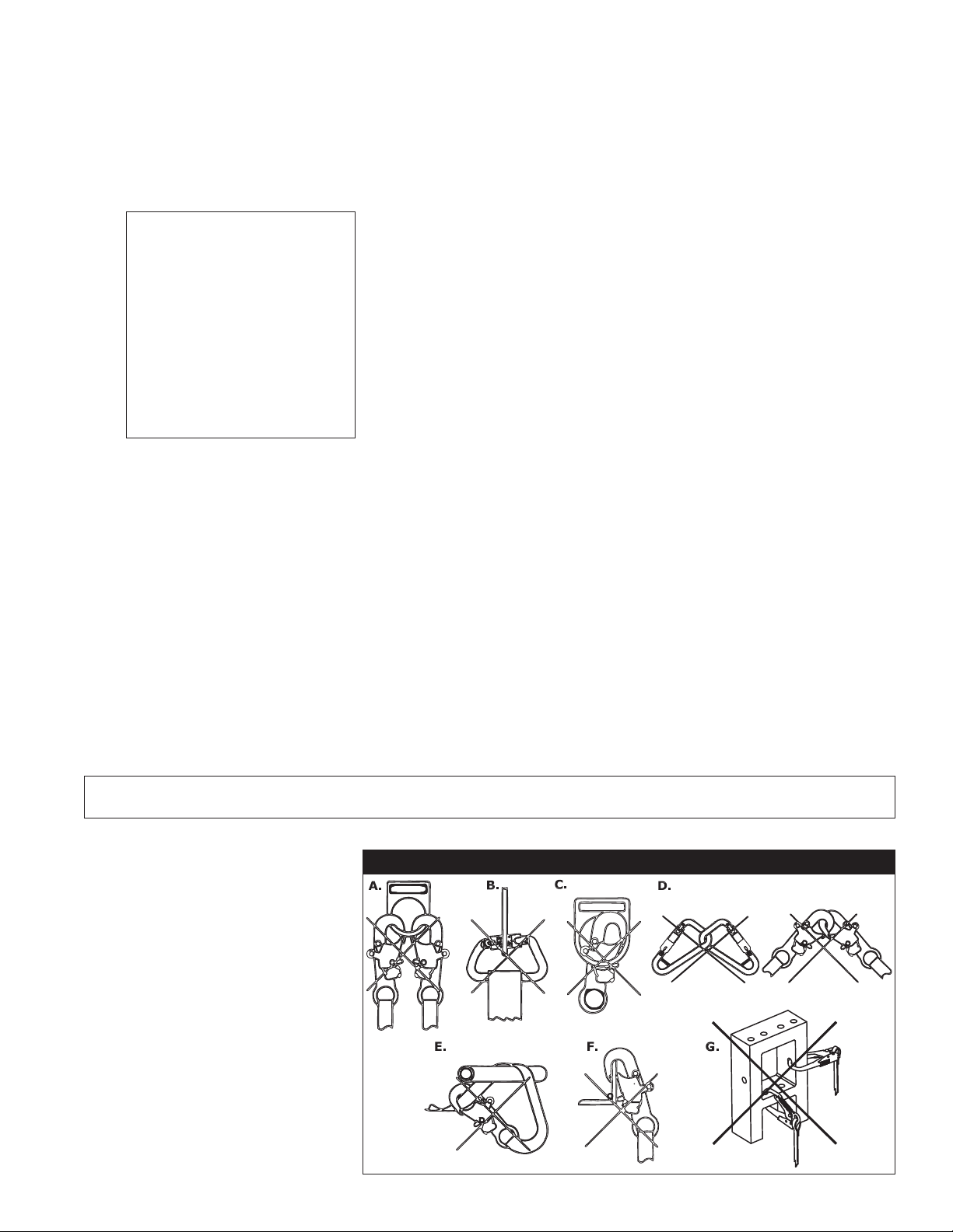
product’s user instructions. See Figure 3 for inappropriate connections. DBI-SALA snap hooks and carabiners
should not be connected:
A. To a D-ring to which another connector is attached.
B. In a manner that would result in a load on the gate.
NOTE: Large throat-opening
snap hooks should not be
connected to standard size
D-rings or similar objects
which will result in a load on
the gate if the hook or D-ring
twists or rotates. Large throat
snap hooks are designed
for use on xed structural
elements such as rebar or
cross members that are not
shaped in a way that can
capture the gate of the hook.
C. In a false engagement, where features that protrude from the snap hook or carabiner catch on the
anchor, and without visual confirmation seems to be fully engaged to the anchor point.
D. To each other.
E. Directly to webbing or rope lanyard or tie-back (unless the manufacturer’s instructions for both the
lanyard and connector specifically allows such a connection).
F.
To any object which is shaped or dimensioned such that the snap hook or carabiners will not close and lock,
or that roll-out could occur.
G. In a manner that does not allow the connector to align with the fall arrest device (i.e., lanyard) while under
load.
2.3 ANCHORAGE STRENGTH:
have a strength capable of sustaining static loads applied in the directions permitted by the system of at least:
A. 5,000 pounds (22.2kN) for non-certified anchorages, or
B. Two times the maximum arresting force for certified anchorages.
When more than one fall arrest system is attached to an anchorage, the strengths set forth in (A) and (B)
above shall be multiplied by the number of systems attached to the anchorage.
In accordance with ANSI Z359.1, anchorages selected for fall arrest systems shall
WARNING: Anchorages must be rigid. Large deformations of the anchorage will aect system performance,
and may increase the required fall clearance below the system, which could result in serious injury or death.
From OSHA 1926.500 and
1910.66: Anchorages used for
attachment of PFAS shall be
independent of any anchorage
being used to support or
suspend platforms, and capable
of supporting at least 5,000 lbs.
(22.2 kN) per user attached,
or be designed, installed, and
used as part of a complete
PFAS which maintains a safety
factor of at least two, and is
supervised by a qualied person
Anchorages selected for work
positioning systems shall have
a strength capable of sustaining
static loads applied in the
directions permitted by the
system of at least:
Figure 3 - Inappropriate Connections
5
Page 6

A. 3,000 pounds (13.3kN) for non-certified anchorages, or
B. Two times the foreseeable force for certified anchorages.
When more than one work positioning system is attached to an anchorage, the strengths set forth in (A) and
(B) above shall be multiplied by the number of systems attached to the anchorage.
3.0 OPERATION AND USE
WARNING: Do not alter or intentionally misuse this equipment. Consult DBI-SALA when using this equipment
in combination with components or subsystems other than those described in this manual. Some subsystem
and component combinations may interfere with the operation of this equipment. Use caution when using this
equipment around moving machinery, electrical hazards, chemical hazards, and sharp edges. Do not loop the
lanyard around small structural members
WARNING: Working at height has inherent risks. Some risks are noted here but are not limited to the following:
falling, suspension/prolonged suspension, striking objects, and unconsciousness. In the event of a fall arrest and/
or subsequent rescue (emergency) situation, some personal medical conditions may aect your safety. Medical
conditions identied as risky for this type of activity include but are not limited to the following: heart disease,
high blood pressure, vertigo, epilepsy, drug or alcohol dependence, psychiatric illness, impaired limb function
and balance issues. We recommend that your employer/physician determine if you are t to handle normal and
emergency use of this equipment
3.1 BEFORE EACH USE of this equipment, carefully inspect it to assure that it is in good working condition.
Check for worn or damaged parts. Ensure all hardware is present and secure, and is not distorted or have
any sharp edges, burrs, cracks, or corrosion. Ensure self-locking snap hooks or carabiners work properly.
Inspect rope or webbing for wear, cuts, burns, frayed edges, breaks, or other damage. See section 5.0 for
further inspection details. Do not use if inspection reveals an unsafe condition.
3.2 PLAN your fall protection system before starting your work. Take into consideration factors that aect
your safety before, during, and after a fall. The following list gives some important points to consider when
planning your system:
A. ANCHORAGE: Select a rigid anchorage point that is capable of supporting the required loads. See
section 2.3. The anchorage location must be carefully selected to reduce possible free fall and swing
fall hazards and to avoid striking an object during a fall. The anchorage should be generally level
(horizontal) to prevent the anchorage connector from sliding down an incline when in use, which could
cause serious injury to the user.
.
6
Page 7

B. FREE FALL: Personal fall arrest systems must be rigged such that the potential free fall is never greater
than 6 ft. (1.8 m). Avoid working above your anchorage level to avoid an increased free fall distance.
IMPORTANT: Some energy absorbing lanyards, such as EZ Stop® Retrax™ and the Shockwave lanyards, make
use of retracting devices designed to shorten their free length. These devices do not decrease free fall distance
C. FALL ARREST FORCES: The assembled fall arrest system must keep fall arrest forces below 1,800 lbs.
(8.0 kN) when used with a full body harness.
D. FALL CLEARANCE: Should a fall occur, there
must be sufficient clearance in the fall area to
arrest the fall before striking the ground or other
object. Energy absorbers can extend the fall
arrest distance by up to 42 inches (106.7 cm).
Figure 4 shows how to estimate fall clearance
distance when using an energy absorbing lanyard
Figure 4 - Estimating Fall Clearance
“FFD” = Free Fall Distance
“DD” = Energy Absorber Deceleration
distance (3 1/2 ft. [1.1 m])
“H” = Height to dorsal connector when
worker is suspended
“C” = Clearance to obstruction during
fall arrest (1 1/2 ft. [.5 m] required)
“RD” = Required distance below working
surface to nearest obstruction
“RD” = “FFD” + “DD” + “H” + “C”
or energy absorber subsystem. Other factors
may influence the required clearance distances.
For example, using an energy absorbing lanyard
Working Surface
Free Fall Distance “FFD”
6 ft. (1.6 m) maximum allowed
or energy absorber with a rope grab (fall
arrestor) may require additional clearance due to
stretch in the lifeline or sliding of the rope grab
on the lifeline during fall arrest. Some full body
harness models incorporate a sliding (positional)
D-ring in the back as the fall arrest attachment,
movement of this D-ring during fall arrest can
increase the fall clearance distance required. Use
caution when assembling system components
that could act to extend the fall arrest distance
Required Distance below
working surface to nearest
obstruction “RD”
Nearest Obstruction
Energy Absorber
Deceleration Distance
“DD”
Height to Dorsal Connector
when worker is suspended “H”
(and therefore fall clearance required). Refer to
manufacturer’s instructions for each part of the
system for more information on fall clearance.
E. SWING FALLS: Swing falls occur when the anchorage point is not
Clearance to obstruction “C”
1 1/2 ft. (.5 m) minimum required
Figure 5 - Swing Fall Hazard
directly above the point where a fall occurs. The force of striking an
object while swinging (horizontal speed of the user due to the pendulum
affect) can be great and may cause serious injury. In a swing fall
situation, the total vertical fall distance of the user will be greater than if
the user had fallen vertically directly below the anchorage point. The user
must therefore account for an increase in the total free fall distance and
the area needed to safely arrest the fall. Swing falls can be minimized by
working as directly below the anchorage point as possible. Never permit
Swing Fall
Hazard
a swing fall if injury could occur. If a swing fall situation exists in your
application contact DBI-SALA before proceeding. See Figure 5.
F. SHARP EDGES
: Avoid working where the lanyard, subsystem, or other
system components will be in contact with, or abrade against, unprotected
sharp edges.
Do not loop lanyard around small diameter structural members.
If working with this equipment near sharp edges is unavoidable, protection
against cutting must be provided by using a heavy pad or other means over the exposed sharp edge.
G. RESCUE
: The user (employer) must have a rescue plan and the ability to implement it when using this
equipment
H. AFTER A FALL: Lanyards with integral energy absorbers, or energy absorber components which have
been subjected to the forces of arresting a fall must be removed from service and destroyed. See
Figure 18.
WARNING: Read and follow manufacturer’s instructions for associated equipment (full body harness, rope grab,
etc.) used in your fall protection system.
IMPORTANT: For special (custom) versions of this product, follow the instructions herein. If included, see
supplement for additional instructions.
3.3 MAKING CONNECTIONS: See Figure 6 for hook operation. When using a hook to connect to an
anchorage, or when coupling components of the system together, ensure accidental disengagement (rollout) cannot occur. Roll-out occurs when interference between a hook and the mating connector causes the
hook’s gate or keeper to accidentally open and release. Roll-out may occur when a hook is connected to an
undersized ring such as an eye bolt or other non-compatible shaped connector. Self-locking snap hooks or
self-locking and self-closing gate carabiners should be used to reduce the possibility of roll-out when making
connections. Do not use hooks or connectors that will not completely close over the attachment object. For
7
Page 8

these situations, use a tie-o adaptor or other anchorage connector to allow a compatible connection. Do
not knot the lanyard in any manner, and do not hook the lanyard back into itself (choker style). Snap hooks
and carabiners must not be connected to each other. Do not attach snap hooks to web loops.
Figure 6 - Making Connections
Push
Pull Back Gate
with Thumb
Depress Locking
Mechanism with
Index Finger
Step 1 Step 2
Up
Rotate
Clockwise
Step 1 Step 2 Step 3
Push
Rotate
Clockwise
Inward
Step 1 Step 2 Step 1 Step 2
Push
Inward
Push
Inward
Depress Locking
Mechanism with
Palm of Hand
A. CONNECTING TO ANCHORAGE OR
ANCHORAGE CONNECTOR: See
Figure 7. Always connect the energy
absorber end of the lanyard to the body
support (harness). Connect the lanyard end
Anchorage
Connector
to the anchorage or anchorage connector.
Component style energy absorbers should
be connected to the body support first,
then coupled to the rest of the system.
Some anchorage connector devices may be
supplied with permanently attached energy
absorber. Use of an additional energy
absorber or energy absorbing lanyard
with these types of subsystems is not
recommended.
100% Tie-off Lanyard Considerations:
Commonly known as 100% tie-off, “Y” type, twin leg, or
double lanyards; these energy absorbing lanyards can be
used to provide continuous fall protection while ascending,
descending, or moving laterally. With one lanyard leg attached,
the worker can move to a new location, attach unused
lanyard leg, and disconnect attached leg. This procedure is
repeated until a new location is reached. With the EZ Stop®
II Shockwave 100% tie-off type lanyard, only one leg of the
lanyard shall be attached to the anchorage or anchorage
connector once a working location is reached. Other practices
that must be followed in order to use a 100% tie-off type
lanyard safely include:
Figure 10 - Incorrect
Attachment
1. The energy absorber portion of the lanyard
must be connected to the dorsal D-ring only.
Do not attach
Energy Absorber
to anchor
Use only the snap hook (or other connector provided) to attach the
energy absorber portion directly to the harness dorsal D-ring. See Figures 8 and 9.
2. Do not connect the energy absorber to the anchorage. See Figure 10.
3. Do not attach the unused leg of the lanyard back to the harness at any location unless
a specially designed lanyard retainer is provided for this purpose. See Figure 11.
Figure 7 - Connecting to Anchorage
Anchorage
Connector
Energy Absorbing
Lanyard
Energy Absorbing
Lanyard
Figure 8 - Correct
Attachment
Connecting
Subsystem
(Rope Grab)
Energy Absorber
attached to
dorsal D-ring
Figure 9 - Incorrect
Attachment
Anchorage
Connector
Energy
Absorbing
Lanyard
Energy Absorber
not attached
to dorsal D-ring
4. Connection of both lanyard legs to separate anchorage points is acceptable. See
Figure 12.
8
Page 9

Figure 11 - Acceptable Designed Retainers
Figure 12 - Acceptable
Attachment
5. When leapfrogging from one anchorage point to the next (such as traversing a
horizontal or vertical structure) do not connect to anchorage points that are further
apart than the lanyard length (as marked on the lanyard label). See Figure 13.
6. Never connect more than one person to a “Y” type lanyard at a time.
7. Do not allow any lanyard to pass under arms or legs during use.
Attaching a Tie-Back Lanyard: See Figure 14. Place the tie-back lanyard over the
Figure 14 - Attaching Tie-Back
Do not allow gate to
contact anchorage
member
anchoring structure. Ensure the lanyard is not twisted.
Adjust the floating D-ring so it hangs below the anchoring
structure. Attach the lanyard end hook to the floating
D-ring.
Attaching a Shockwave 2 Tie-Back Lanyard
Shockwave 2 Tie-back lanyards (model no. 1244650 and
1244675) are the only Shockwave
Figure 15 - Shockwave 2 Tie-Back
models suitable for tie back
applications. Do not use regular
Shockwave 2 models for tie back
applications.
Tie back using the captive eye
Proper Connection
Improper Connection
carabiner only. Do not tie back using
the snap hook. The snap hook must
Figure 16 - Attaching Wire Form
be connected to the user’s harness.
Anchorage size limit: The red
stitching must be outside of the
captive eye carabiner when the
lanyard is tight around the anchorage (under hand tension). See gure 15.
Proper Connection
WARNING: Tying back beyond the red stitching will limit the amount of
energy absorption in the event of a fall and could result in serious injury or
death
Load Direction
If the stitching is located outside of the carabiner, choose an anchorage of
smaller size (in accordance with the requirements in section 2.3) to prevent
tying back beyond the red stitching.
Improper
Connection
Load Direction
Ensure the lanyard is cinched tight around the anchorage during use.
ATTACHING A LANYARD WITH WIRE FORM PIPE HOOK: The wire form
Load Direction
Improper
Connection
pipe hook is intended for use with pipes up to 3 inches (7.6 cm) in diameter.
The anchorage must be geometrically compatible in size and shape. See Figure 16 for examples of
proper and improper connections and intended load directions. Do not side load the pipe hook. Do
not allow the pipe hook to contact electrical sources. Squeeze the handle to open the hook. Place
hook around the anchorage and release handle. Only use a carabiner as the connecting element when
attaching a personal fall arrest system to a pipe hook. When connecting to an anchorage, ensure the
hook fully closes and closure hooks engage eye loops on hook body.
B. CONNECTING TO THE BODY SUPPORT:
Connect the energy absorbing lanyard or energy absorber
to the D-ring on the back between the shoulders (dorsal D-ring) on a full body harness. Connect so the
energy absorber portion of the lanyard is on the body support side. DBI-SALA does not recommend using
a body belt for fall arrest applications. If using a body belt, connect the energy absorbing lanyard or
energy absorber to the D-ring and position the belt so the D-ring is located on the back side of the body.
Red
Stitch
Figure 13 - Max Lanyard
Max ≤
OK
NO
Reach
Lanyard
Length
Red
Stitch
9
Page 10

ATTACHING A LANYARD WITH WEB LOOPS: See Figure 17.
Figure 17 - Web Loop Connection
1. Insert the energy absorbing lanyard web loop through the
harness web loop or D-ring.
Insert lanyard web loop through
2. Insert the opposite end of the energy absorbing lanyard through
web loop or D-ring on harness
the connecting web loop.
3. Pull the attached energy absorbing lanyard through the
Energy Absorbing Lanyard
connecting web loop to secure.
C. CONNECTING TO A ROPE GRAB (FALL ARRESTOR): It is
recommended the lanyard end (vs. the energy absorber end)
be attached to the rope grab. This recommendation is made
Insert opposite end of lanyard
through the lanyard web loop
to reduce possible interference with the operation of the rope
grab by the energy absorber “pack”. Attaching a component
style energy absorber to a rope grab is not recommended, with
the exception of a “direct-coupling” between a rope grab and a
Pull the lanyard through the
connecting web loop to secure
harness. Some rope grabs may be supplied with a permanently
attached energy absorbing lanyard. For these cases, use of an additional energy absorber connected
between the rope grab and the body support is not recommended. In some cases it may be permissible
to couple an energy absorber component between the anchorage (or anchorage connector) and the
rope grab lifeline. In all cases, ensure the length of the energy absorber or energy absorbing lanyard
does not exceed the rope grab manufacturer’s recommended maximum connection length (3 feet [.9 m]
maximum per ANSI Z359.1).
D. CONNECTING TO SELF RETRACTING LIFELINE: DBI-SALA does not recommend connecting an
energy absorbing lanyard or energy absorber component to a self retracting lifeline. Special applications
do exist where it may be permissible. Contact DBI-SALA if considering connecting an energy absorbing
lanyard to a self retracting lifeline.
3.4 ADJUSTING THE RETRAX™ LANYARD: The amount of
the lanyard that is retracted into the Retrax housing can
Figure 18 - Adjusting the Retrax Lanyard Length
be adjusted by completely extending the lanyard from the
housing, then sliding the housing up or down the lanyard.
1. Fully extend the lanyard from the Retrax housing
See Figure 18. Adjusting the length of lanyard that is
retracted into the housing will not reduce the amount of fall
clearance needed to arrest a fall. See section 3.2.
WARNING: The Retrax lanyard is designed to retract and
store the lanyard strap. It is not designed to “lock” or limit the
2. Slide the Retrax housing away from the center of the lanyard
lanyard length in a fall.
3.5 After use, return the lanyard for cleaning or storage as described in section 6.0
Harness web loop
or D-ring
Web loop on
4.0 TRAINING
4.1
It is the responsibility of all users of this equipment to understand these instructions, and to be trained in the correct
installation, use, and maintenance of this equipment. These individuals must be aware of the consequences of improper
installation or use of this equipment. This user manual is not a substitute for a comprehensive training program. Training
must be provided on a periodic basis to ensure prociency of the users.
IMPORTANT: Training must be conducted without exposing the trainee to a fall hazard. Training should be
repeated on a periodic basis.
5.0 INSPECTION
5.1 FREQUENCY
• Before each use visually inspect per steps listed in sections 5.2 and 5.3.
• Annually: The lanyard must be inspected by a competent person (see section 8 Terminology) other
than the user at least annually. See sections 5.2 and 5.3 for guidelines. Record the results of each
inspection in the inspection and maintenance log in section 9.0, or use the inspection web portal if an
i-Safe™ RFID tag is present (see Figure 19). If you are registered i-Safe user, go to www.capitalsafety.
com/isafe. For more information contact a Customer Service representative in the US at 1-800-3286146 or in Canada at 1-800-387-7484.
IMPORTANT
impact forces, the user, authorized person, or rescuer must remove it from service immediately and destroy it.
IMPORTANT: Extreme working conditions (harsh environment, prolonged use, etc.) may require increasing the
frequency of inspections.
: If the energy absorbing lanyard or energy absorber component has been subjected to fall arrest or
10
Page 11

Figure 19 - i-Safe RFID Tag
Figure 20 - Inspecting the Energy Abosrber for Activation
i-Safe
RFID Tag
The following inspection items are indications
that the Energy Absorber has been subjected
to impact loading and has been activated.
Open end or ripped
out stitching
more than 6 in. (15 cm) longer than the
Torn or broken cover
Measured length is
length marked on the label.
Torn webbing
5.2 INSPECTION STEPS
Step 1. Inspect energy absorbing lanyard or energy absorber component hardware (snap hooks, adjusters,
swages, thimbles, etc.). These items must not be damaged, broken, distorted, or have any sharp
edges, burrs, cracks, worn parts, or corrosion. Ensure the connecting hooks work properly. Hook
gates must move freely and lock upon closing. Ensure adjusters (if present) work properly.
Step 2. Inspect the energy absorbing lanyard or energy absorber component per the following as
applicable:
WEBBING AND STITCHING: The webbing material must be free of frayed, cut, or broken
bers. Check for tears, abrasions, mold, burns, or discoloration, etc. The webbing must be free
of knots, excessive soiling, heavy paint buildup, and rust staining. Check for chemical or heat
damage indicated by brown, discolored, or brittle areas. Check for ultraviolet damage indicated
by discoloration and the presence of splinters or slivers on the webbing surface. All of the above
factors are known to reduce webbing strength. Damaged or questionable webbing should be
replaced. Inspect stitching for pulled or cut stitches. Broken stitches may be an indication the
energy absorbing lanyard or energy absorber component has been impact loaded and must be
removed from service.
WIRE ROPE: Inspect entire length of the wire rope. Always wear protective gloves when
inspecting wire rope. Inspect for broken wires by passing cable through gloved hands, exing it
every few inches to expose breaks. Broken wires can be removed by bending the wire back and
forth parallel to the rope length. Do not attempt to pull wires out of rope. Remove the energy
absorbing lanyard from service immediately and destroy if there are six or more randomly
distributed broken wires in one lay, or three or more broken wires in one strand in one lay.
A “lay” of wire rope is the length of wire rope that it takes for a strand (the larger groups of
wires) to complete one revolution or twist along the rope. Remove the energy absorbing lanyard
from service immediately and destroy if there are any broken wires within 1 inch of the metal
compression sleeves (swages) at either end of the assembly. The wire rope should be free of
corrosion.
Step 3. ENERGY ABSORBING COMPONENT: Inspect energy absorber to determine if it has been
activated. There should be no evidence of elongation. See Figure 20. Ensure energy absorber
cover is secure and not torn or damaged. On the Shockwave 2™ Lanyard models, the lanyard
webbing will tear out to reveal the warning on the impact indicator label. See section 8.2 for label
illustration.
Step 4. All labels should be present and fully legible. See section 8.0.
Step 5. Inspect each system component or subsystem per associated manufacturer’s instructions.
Step 6. Record the inspection date and results in the inspection log in section 9.0.
5.3 If inspection reveals an unsafe condition, remove unit from service immediately and destroy, or contact an
authorized service center for repair.
NOTE: Only DBI-SALA or parties authorized in writing may make repairs to this equipment.
11
Page 12

6.0 MAINTENANCE, SERVICING, STORAGE
6.1 Clean lanyard with water and a mild detergent solution. Wipe o hardware with a clean, dry cloth, and
hang to air dry. Do not force dry with heat. If you have any questions regarding cleaning of this equipment,
or require more information, contact DBI-SALA. An excessive buildup of dirt, paint, etc., may prevent the
lanyard from working properly, and in severe cases degrade the webbing or rope to a point where it has
become weakened and should be removed from service. If you have any questions concerning the condition
of your lanyard, or have any doubt about putting it into service, contact DBI-SALA.
6.2 Additional maintenance and servicing procedures (replacement parts) must be completed by a factory
authorized service center. Authorization must be in writing. Do not disassemble the unit. See section 5.1 for
inspection frequency.
6.3 Store the lanyard in a cool, dry, clean environment out of direct sunlight. Avoid areas where chemical vapors
may exist. Thoroughly inspect the lanyard or energy absorber component after extended storage.
7.0 SPECIFICATIONS
- The maximum arresting force of DBI-SALA Energy Absorbing Lanyards and components when
dynamically tested in accordance with ANSI Z359.1 is 900 lbs. (4 kN). (EZ STOP® III and
ShockWave 2 models less than 6 ft. [1.8 m] in length, maximum arresting force is 1800 lbs. [8 kN],
Shockwave 2 Tie-back, maximum arrresting force is 1350 lbs [6 kN]).
- The maximum elongation of the Energy Absorbing Lanyard or Energy Absorber component when
dynamically tested in accordance with ANSI Z359.1 is 42 in. (1 m).
- Maximum free fall distance must be no greater than 6 ft. (1.8 m) per federal law and ANSI Z359.1
- EZ STOP® II U.S. Patent Number 5,174,410
- 9503175 Self-closing and self-locking snap hook U.S. Patent Number 4,977,647, Can. 2,027,784.
Lanyard Model Energy Absorber Specifications Adjustable/
Fixed Length
EZ Stop II Web Lanyards
Adjustable Length
EZ Stop II Web Lanyards
100% Tie-off
EZ Stop II Web Lanyards
EZ Stop II Energy
Absorber Component
EZ Stop II
Cable Lanyards
EZ Stop III
Web Lanyards
EZ Stop II Tie-back
Web Lanyard
EZ Stop II Tie-back
100% Tie-off Web Lanyard
EZ Stop II Shockwave
Shockwave 2
Shockwave 2 Tie Back
EZ Stop II Retrax
Web Lanyard
1 3/4 in. (4.4 cm) polyester web strength
member, tubular nylon web wear pads both ends,
nylon outer cover, polyester thread, 8,800^lb.
(39.1^kN) tensile strength.
1 3/4 in. (4.4 cm) polyester web strength
member, tubular nylon web wear pads both ends,
nylon outer cover, polyester thread, 8,800^lb.
(39.1^kN) tensile strength.
1 3/4 in. (4.4 cm) polyester web strength
member, tubular nylon web wear pads both ends,
nylon outer cover, polyester thread, 8,800^lb.
(39.1 kN) tensile strength.
1 3/4 in. (4.4 cm) polyester web strength
member, tubular nylon web wear pads both ends,
nylon outer cover, polyester thread, 8,800^lb.
(39.1^kN) tensile strength.
1 3/4 in. (4.4 cm) polyester web strength
member, nylon web wear pads both ends,
nylon outer cover, polyester thread, 8,800^lb.
(39.1^kN) tensile strength.
1 3/8 in. (3.5 cm) tubular polyester web strength
member, nylon web wear pads both ends,
polyester thread, 8,800^lb. (39.1^kN) tensile
strength.
1 3/4 in. (4.4 cm) polyester web strength
member, tubular nylon web wear pads both ends,
nylon outer cover, polyester thread, 8,800^lb.
(39.1^kN) tensile strength.
1 3/4 in. (4.4 cm) polyester web strength
member, tubular nylon web wear pads both ends,
nylon outer cover, polyester thread, 8,800^lb.
(39.1^kN) tensile strength.
1 3/4 in. (4.4 cm) polyester web strength
member, tubular nylon web wear pads both ends,
nylon outer cover, polyester thread, 8,800^lb.
(39.1^kN) tensile strength.
1 15/16 in. (4.9 cm) polyester web strength
member, nylon web wear pads both ends,
polyester thread, 6,000 lb. (26.7^kN) tensile
strength.
1 7/8 in. (4.8 cm) polyester web strength
member, nylon web wear pads both ends,
polyester thread, 8,500 lb. (37.7^kN) tensile
strength.
1 3/4 in. (4.4 cm) polyester web strength
member, nylon web wear pads both ends, nylon
outer cover, polyester thread, 6,000 lb. (26.7 kN)
tensile strength.
Fixed Length
Lanyard Specifications
Fixed
Adjustable
Fixed
Fixed Not Applicable
Fixed
Fixed
Fixed
Fixed
Fixed
Fixed Lanyard and energy absorber are the same material.
Fixed Lanyard and energy absorber are the same material.
Fixed
1 in. (2.5 cm) polyester web, 8,800^lb. (39.1^kN)
1 in. (2.5 cm) polyester web, 8,800^lb. (39.1^kN)
1 in. (2.5 cm) polyester web, 100% tie-off, 8,800^lb.
7/32 in. (.6 cm) 7x9 galvanized cable, vinyl covered.
5,600 lb. (24.9 kN) tensile strength
1 3/8 in. (3.5 cm) tubular polyester web strength
member, 6,000 lb. (26.7 kN) tensile strength
1 in. (2.5 cm) polyester web strength member,
8,800^lb. (39.1^kN) tensile strength with 1 3/8 in.
(3.5 cm) tubular polyester web cover
1 in. (2.5 cm) polyester web strength member,
8,800^lb. (39.1^kN) tensile strength with 1 3/8 in.
(3.5 cm) tubular polyester web cover
1 15/16 in. (4.9 cm) tubular polyester web strength
member, 6,000 lb. (26.7 kN) tensile strength
1 3/8 in. polyester web, 6,000 lb. (26.7 kN) tensile
tensile strength
tensile strength
(39.1^kN) tensile strength
strength
12
Page 13

8.0 TERMINOLOGY
Authorized Person: A person assigned by the employer to perform duties at a location where the person will
be exposed to a fall hazard (otherwise refered to as “user” for the purpose of these instructions).
Rescuer: Person or persons other than the rescue subject acting to perform an assisted rescue by operation
of a rescue system.
Certified Anchorage: An anchorage for fall arrest, positioning, restraint, or rescue systems that a qualified
person certifies to be capable of supporting the potential fall forces that could be encountered during a fall
or that meet the criteria for a certified anchorage prescribed in this standard.
Qualified Person: A person with a recognized degree or professional certificate and with extensive
knowledge, training, and experience in the fall protection and rescue field who is capable of designing,
analyzing, evaluating and specifying fall protection and rescue systems to the extent required by this
standard.
COMPETENT PERSON: One who is capable of identifying existing and predictable hazards in the surroundings
or working conditions which are unsanitary, hazardous, or dangerous to employees, and who has
authorization to take prompt corrective measures to eliminate them.
9.0 LABELING
9.1 This label must be attached to all lanyards and be fully legible.
All Lanyards - Inspection Log
9.2 These labels must be securely attached to all Shock Wave 2™ Lanyards and be fully legible.
All ShockWave 2 Lanyards - I.D. / Warning Label
13
Page 14

9.3 These labels must be securely attached to the noted CSA approved lanyards and be fully legible.
Warning Label - All CSA Approved Lanyards
ID / Warning Label - CSA Approved EZ Stop® II Web Lanyards
ID Label - CSA Approved EZ Stop® III Web Lanyards
9.4 These labels must be attached to the noted Energy Absorbing Lanyards or Energy Absorber components
and be fully legible.
ID Label - EZ Stop® II Web Lanyards
Warning Label - All Web Loop
Energy Absorbing Lanyards Not
Permanently Attached to Harness
Warning Label EZ Stop® II
Tie-Back Lanyards
Warning Label - All Web Loop
Energy Absorbing Lanyards
Permanently Attached to Harness
14
Page 15

9.4 CONTINUED . . .
These labels must be attached to the noted Energy Absorbing Lanyards or Energy Absorber components and
be fully legible.
Impact Indicator Label
EZ Stop® Shock Wave 2 Tie-Back Lanyards
And
EZ Stop® Shock Wave III Lanyards
Shockwave 2 Tie Back Lanyards ID Label Front and Back
Retrax Warning Label
100% Tie-off Lanyard
Warning Label
Shockwave 2 Tie
Back Lanyards
Warning Label
All EZ Stop III ANSI Approved Lanyards - I.D. / Warning Label
Shockwave 2 Tie Back Lanyards
Impact Indicator Label
15
Page 16

10.0 INSPECTION AND MAINTENANCE LOG
SERIAL NUMBER:
MODEL NUMBER:
DATE PURCHASED: DATE OF FIRST USE:
INSPECTION DATE INSPECTION ITEMS
NOTED
Approved By:
Approved By:
Approved By:
Approved By:
Approved By:
Approved By:
Approved By:
Approved By:
CORRECTIVE ACTION MAINTENANCE
PERFORMED
Approved By:
Approved By:
Approved By:
Approved By:
Approved By:
Approved By:
Approved By:
Approved By:
Approved By:
Approved By:
16
Page 17

Models - ANSI:
1100456
1100750
1100756
1100762
1100767
1100768
1100769
1101240
1101241
1101272
1101340
1101341
1101633
1101635
1101645
1101646
1101647
1101775
1101789
1101790
1101792
1101793
1101795
1101832
1101835
1101836
1101837
1101851
1101859
1101866
1101869
1102525
1103886
1104729
1104744
1104745
1104746
1104747
1104748
1104912
1104918
1104924
1105376
1105491
1106002
1106003
1106005
1106007
1106008
1106016
1106017
1106033
1106040
1106041
1106058
1106059
1106063
1106064
1106074
1106150
1106151
1106152
1106203
1106211
1106212
1106325
1106326
1106327
1106328
1106329
1106330
1106331
1106332
1106333
1106334
1106679
1106682
1106683
1106684
1106687
1106900
1106901
1106902
1106903
1106904
1106905
1107026
1107575
1107576
1107650
1107652
1107725
1107727
1107875
1107951
1107952
1107958
1107959
1107962
1107991
1107992
1108033
1108034
1108301
1108310
1109105
1109106
1109111
1110792
1110793
1220002
1220003
1220004
1220005
1220006
1220007
1220011
1220013
1220014
1220016
1220017
1220019
1220022
1220024
1220026
1220027
1220028
1220029
1220030
1220033
1220034
1220035
1220037
1220038
1220040
1220043
1220045
1220046
1220048
1220053
1220066
1220067
1220068
1220070
1220071
1220074
1220077
1220078
1220079
1220081
1220083
1220086
1220087
1220091
1220098
1220103
1220105
1220108
1220111
1220115
1220120
1220123
1220124
1220127
1220132
1220135
1220140
1220146
1220148
1220153
1220154
1220156
1220157
1220170
1220175
1220178
1220186
1220194
1220197
1220200
1220201
1220203
1220207
1220251
1220253
1220256
1220258
1220259
1220262
1220265
1220267
1220268
1220269
1220271
1220272
1220274
1220275
1220277
1220279
1220285
1220286
1220288
1220289
1220291
1220292
1220295
1220298
1220299
1220300
1220352
1220354
1220358
1220359
1220362
1220363
1220364
1220365
1220366
1220368
1220399
1220405
1220406
1220409
1220411
1220412
1220413
1220414
1220416
1220417
1220419
1220421
1220424
1220427
1220428
1220433
1220436
1220437
1220446
1220447
1220448
1220452
1220453
1220462
1220463
1220464
1220465
1220466
1220467
1220469
1220471
1220472
1220473
1220474
1220475
1220509
1220510
1220511
1220525
1220526
1220535
1220536
1220537
1220538
1220540
1220551
1220553
1220557
1220558
1220559
1220562
1220563
1220564
1220566
1220567
1220568
1220570
1220571
1220573
1220574
1220601
1220620
1220626
1220680
1220681
1220682
1220701
1220704
1220705
1220706
1220707
1220708
1220712
1220713
1220716
1220718
1220720
1220722
1220724
1220725
1220726
1220727
1220729
1220739
1220740
1220745
1220746
1220748
1220749
1220751
1220753
1220757
1220775
1220803
1220804
1220806
1220808
1220809
1220845
1220846
1220847
1220848
1220849
1220850
1220852
1220854
1220855
1220856
1220857
1220859
1220860
1220861
1220862
1220863
1220865
1220870
1220871
1220872
1220873
1220874
1220880
1220902
1220903
1220905
1220906
1220909
1220914
1220915
1220917
1220922
1220925
1220929
1220932
1220975
1221001
1221002
1221003
1221004
1221005
1221006
1221008
1221009
1221013
1221016
1221030
1221031
1221032
1221033
1221101
1221102
1221104
1221105
1221106
1221107
1221108
1221112
1221114
1221115
1221116
1221117
1221119
1221120
1221205
1221206
1221209
1221210
1221211
1221215
1221216
1221217
1221251
1221276
1221327
1221401
1221451
1221460
1221461
1221462
1221463
1221464
1221480
1221481
1221482
1221702
1221751
1221752
1222300
1223026
1224003
1224005
1224006
1224007
1224008
1224009
1224011
1224012
1224013
1224014
1224016
1224018
1224023
1224024
1224026
1224027
1224029
1224031
1224034
1224036
1224038
1224041
1224043
1224047
1224101
1224102
1224103
1224107
1224110
1224111
1224252
1224253
1224301
1224302
1224305
1224306
1224307
1224308
1224309
1224310
1224311
1224312
1224313
1224314
1224319
1224321
1224322
1224323
1224324
1224325
1224327
1224329
1224330
1224331
1224335
1224336
1224337
1224338
1224339
1224344
1224345
1224346
1224347
1224349
1224350
1224354
1224355
1224356
1224402
1224404
1224405
1224406
1224409
1224410
1224411
1224412
1224413
1224414
1224416
1224418
1224419
1224420
1224421
1224424
1224425
1224430
1224431
1224433
1224434
1224435
1224436
1224437
1224439
1224440
1224441
1224442
1224443
1224444
1224445
1224447
1224455
1224456
1224457
1224458
1224475
1224476
1224510
1224610
1224611
1224612
1224613
1224630
1224631
1224632
1224633
1224634
1226000
1226001
1226003
1229000
1240004
1240005
1240006
1240007
1240011
1240012
1240013
1240016
1240017
1240018
1240019
1240020
1240023
1240024
1240027
1240028
1240029
1240030
1240034
1240035
1240038
1240039
1240040
1240041
1240043
1240046
1240048
1240053
1240054
1240057
1240058
1240059
1240060
1240062
1240063
1240066
1240067
1240068
1240071
1240074
1240077
1240080
1240082
1240083
1240084
1240086
1240088
1240089
1240090
1240091
1240092
1240093
1240097
1240098
1240101
1240102
1240103
1240105
1240108
1240111
1240113
1240114
1240115
1240117
1240118
1240120
1240122
1240123
1240124
1240125
1240126
1240127
1240128
1240129
1240130
1240131
1240132
1240135
1240136
1240137
1240139
1240140
1240141
1240142
1240143
1240144
1240147
1240150
1240153
1240154
1240155
1240156
1240157
1240158
1240168
1240170
1240175
1240178
1240179
1240186
1240188
1240193
1240194
1240197
1240200
1240201
1240202
1240205
1240208
1240209
1240210
1240211
1240251
1240253
1240256
1240257
1240258
1240259
1240262
1240263
1240264
1240265
1240266
1240267
1240268
1240269
1240271
1240272
1240273
1240274
1240276
1240277
1240278
1240279
1240280
1240281
1240282
1240291
1240292
1240294
1240295
1240299
1240351
1240354
1240357
1240359
1240362
1240368
1240399
1240405
1240406
1240409
1240411
1240412
1240414
1240415
1240416
1240419
1240421
1240424
1240427
1240428
1240430
1240431
1240432
1240433
1240436
1240440
1240441
1240445
1240446
1240447
1240448
1240452
1240453
1240458
1240460
1240462
1240463
1240464
1240465
1240466
1240467
1240469
1240470
1240471
1240472
1240473
1240474
1240475
1240476
1240477
1240505
1240506
1240508
1240509
1240510
1240511
1240525
1240526
1240535
1240536
1240537
1240538
1240540
1240551
1240552
1240553
1240554
1240555
1240556
1240557
1240558
1240560
1240561
1240565
1240566
1240567
1240568
1240570
1240573
1240574
1240601
1240603
1240604
1240620
1240626
1240627
1240680
1240681
1240682
1240683
1240702
1240703
1240704
1240705
1240706
1240707
1240708
1240710
1240711
1240712
1240713
1240714
1240715
1240716
1240717
1240718
1240719
1240720
1240722
1240723
1240724
1240725
1240726
1240727
1240729
1240730
1240731
1240732
1240733
1240734
1240735
1240736
1240737
1240738
1240739
1240740
1240741
1240742
1240743
1240744
1240745
1240746
1240748
1240749
1240750
1240752
1240753
1240754
1240755
1240756
1240757
1240801
1240802
1240803
1240804
1240805
1240806
1240807
1240808
1240809
1240845
1240846
1240847
1240848
1240849
1240850
1240852
1240854
1240855
1240856
1240857
1240859
1240860
1240861
1240862
1240863
1240865
1240870
1240871
1240872
1240873
1240874
1240875
1240876
1240877
1240878
1240879
1240880
1240901
1240902
1240903
1240904
1240905
1240906
1240907
1240909
1240910
1240911
1240912
1240913
1240914
1240915
1240916
1240922
1240923
1240924
1240926
1240927
1240928
1240929
1240930
1240932
1240935
1240975
1241001
1241002
1241003
1241004
1241005
1241006
1241008
1241009
1241010
1241013
1241014
1241016
1241018
1241020
1241022
1241023
1241024
1241025
1241029
1241030
1241031
1241032
1241033
1241101
1241102
1241103
1241105
1241106
1241108
1241109
1241110
1241111
1241112
1241113
1241114
1241117
1241118
1241120
1241122
1241124
1241125
1241201
1241204
1241205
1241206
1241207
1241210
1241211
1241213
1241214
1241215
1241216
1241217
1241218
1241219
1241220
1241250
1241251
1241276
1241277
1241326
1241327
1241460
1241461
1241462
1241463
1241464
1241465
1241480
1241481
1241482
1241483
1241701
1241702
1241751
1241752
1241761
1241763
1242475
1242476
1242500
1243026
1244001
1244003
1244004
1244006
1244007
1244008
1244009
1244010
1244011
1244012
1244013
1244014
1244016
1244018
1244021
1244023
1244024
1244026
1244027
1244028
1244029
1244030
1244031
1244032
1244033
1244034
1244035
1244036
1244037
1244038
1244039
1244040
1244041
1244043
1244047
1244101
1244102
1244103
1244104
1244106
1244107
1244112
1244205
1244213
1244251
1244252
1244253
1244254
1244301
1244302
1244303
1244304
1244305
1244306
1244307
1244308
1244309
1244310
1244311
1244312
1244313
1244314
1244317
1244318
1244319
1244321
1244324
1244325
1244326
1244327
1244329
1244331
1244332
1244335
1244338
1244340
1244344
1244346
1244349
1244351
1244353
1244354
1244355
1244356
1244357
1244358
1244359
1244360
1244402
1244403
1244404
1244406
1244409
1244410
1244411
1244412
1244413
1244414
1244415
1244417
1244420
1244424
1244425
1244426
1244430
1244433
1244434
1244435
1244436
1244439
1244440
1244441
1244442
1244443
1244444
1244445
1244446
1244448
1244455
1244456
1244457
1244458
1244475
1244476
1244510
1244601
1244610
1244611
1244612
1244613
1244614
1244630
1244631
1244632
1244633
1244634
1244650
1244675
1244676
1244700
1244725
1244750
1244751
1246001
1246002
1246190
1246491
1330025
1330035
1330055
1330065
1330100
5002040
5002041
5002042
5002050
5900876
5900877
Additional model numbers may appear on the next printing of these instructions.
17
Page 18

Models - CSA:
CSA Class Model Numbers
E4:
E6:
Max. Arresting Force Max. Elongation Min. Mass of Worker Max. Mass of Worker
900 lbf (4.0 kN) 3.9 ft (1.2 m) 100 lbs (45 kg) 254 lbs (115 kg)
1100320C
1100321C
1100322C
1100323C
1100447C
1100448C
1100449C
1100450C
1100890C
1100891C
1100892C
1100893C
1100894C
1100980C
1100981C
1100982C
1100983C
1101166C
1101167C
1101168C
1101169C
1101170C
1101535C
1101536C
1101537C
1101538C
1101540C
1101851C
1101859C
1101871C
1102319C
1102320C
1102321C
1102967C
1102968C
1102969C
1102970C
1102971C
1103266C
1103268C
1103269C
1103387C
1103388C
1103389C
1103390C
1103391C
1103392C
1105855C
1106015C
1106040C
1106041C
1106042C
1106053C
1106054C
1106060C
1106061C
Max. Arresting Force Max. Elongation Min. Mass of Worker Max. Mass of Worker
1,300 lbf (6.0 kN) 5.7 ft (1.75 m) 200 lbs (90 kg) 386 lbs (175 kg)
1242225C
1242226C
1242227C
1242228C
1106062C
1106075C
1106203C
1106684C
1106685C
1106689C
1106690C
1106698C
1106699C
1107160C
1107161C
1107162C
1107163C
1107164C
1107165C
1107837C
1107838C
1107839C
1107840C
1107961C
1108028C
1108355C
1108356C
1108357C
1108358C
1108359C
1108528C
1108529C
1242229C
1242230C
1108530C
1108534C
1108539C
1108540C
1108541C
1108542C
1108603C
1108678C
1108679C
1108680C
1108684C
1108685C
1108686C
1108710C
1108711C
1108712C
1108713C
1108714C
1108715C
1109025C
1109037C
1109038C
1109045C
1109057C
1109058C
1109061C
1109141C
1109432C
1242250C
1242275C
1109433C
1109434C
1109435C
1109436C
1109437C
1110310C
1110311C
1110312C
1110313C
1110612C
1110613C
1110614C
1110619C
1110705C
1110706C
1220006C
1220007C
1220012C
1220016C
1220017C
1220024C
1220028C
1220030C
1220035C
1220038C
1220040C
1220042C
1220043C
1242325C
1242326C
1220046C
1220048C
1220054C
1220058C
1220068C
1220071C
1220074C
1220079C
1220080C
1220086C
1220091C
1220092C
1220093C
1220098C
1220105C
1220108C
1220115C
1220132C
1220139C
1220180C
1220181C
1220182C
1220195C
1220204C
1220206C
1220256C
1220259C
1220269C
1242350C
1242375C
1220296C
1220297C
1220299C
1220300C
1220301C
1220359C
1220362C
1220364C
1220369C
1220406C
1220409C
1220450C
1220451C
1220455C
1220459C
1220461C
1220466C
1220468C
1220526C
1220527C
1220535C
1220536C
1220539C
1220540C
1220553C
1220558C
1220572C
1220601C
1220680C
1220681C
1220850C
1220851C
1220852C
1220853C
1220857C
1220858C
1220861C
1220863C
1220864C
1220866C
1220870C
1220871C
1220873C
1220880C
1220906C
1220937C
1220938C
1220939C
1220940C
1221001C
1221006C
1221028C
1221034C
1221104C
1221106C
1221206C
1221425C
1221426
1221426C
1221460C
1221461C
1221480C
1221481C
1221484C
1221801C
1221802C
1221803C
1221804C
1221805C
1221806C
1221807C
1221808C
1221809C
1221810C
1221811C
1221812C
1221813C
1221814C
1221815C
1221816C
1221851C
1221852C
1221853C
1221854C
1224006C
1224306C
1224341C
1224343C
1224348C
1224405C
1224406C
1224409C
1224427C
1224428C
1224431C
1224438C
1240210C
1240211C
1240256C
1240325C
1240477C
1240559
1244610C
1244611C
1244630C
1244631C
Additional model numbers may appear on the next printing of these instructions.
Page 19

Instruções para os produtos das seguintes séries:
Talabartes EZ Stop
Talabartes ShockWave
Talabartes EZ Stop Retrax
(Consulte os números especícos dos modelos no verso.)
MANUAL DE INSTRUÇÕES DO USUÁRIO
TALABARTES COM ABSORÇÃO INTEGRAL DE ENERGIA E COMPONENTES DE ABSORÇÃO DE
ENERGIA USADOS EM SISTEMAS INDIVIDUAIS DE PREVENÇÃO CONTRA QUEDAS (ANSI Z359.1)
Este manual visa atender às instruções do fabricante conforme a norma ANSI Z359.1 e deve ser usado como
parte de um programa de treinamento de funcionários, conforme as exigências da OSHA.
Figura 1 - Talabartes EZ STOP
®
Talabartes para
teias EZ Stop II
Talabartes EZ Stop
II Shockwave
Talabartes de
cabo EZ Stop II
Talabartes de
amarra EZ Stop II
Talabartes para teias
EZ Stop III
Componente
de absorção de
energia EZ Stop III
Talabarte
Shockwave 2
Talabarte retrátil
EZ Stop Retrax
AVISO: este produto faz parte de um sistema de restrição de quedas individuais, posicionamento de trabalho,
suspensão ou resgate. Estas instruções devem ser fornecidas ao usuário e à pessoa responsável pelo resgate
(consulte a seção 8 - Terminologia). Antes de usar o equipamento, o usuário deve ler e entender essas
instruções ou solicitar que lhe sejam explicadas. O usuário deve ler e seguir as instruções do fabricante para
cada componente ou parte do sistema completo. As instruções do fabricante devem ser seguidas para uso
e manutenção apropriada do produto. Alterações ou negligência na utilização deste produto ou a não
observância destas instruções podem resultar em ferimentos graves ou morte.
IMPORTANTE: se você tiver dúvidas sobre o uso, cuidados e aplicação, ou adequação para o uso deste
equipamento, entre em contato com a DBI-SALA.
IMPORTANTE: antes de usar este equipamento, registre a informação de identicação do produto (localizada
na etiqueta de identicação) no registro de inspeção e manutenção localizado na seção 10.0 deste manual.
DESCRIÇÕES
TALABARTES PARA TEIAS EZ STOP® II
Teia de 2,5 cm (1 pol.), gancho 9503175 em cada extremidade.
Teia de 2,5 cm (1 pol.), gancho 9503175 em uma extremidade, gancho 2007153 na outra.
Teia de 2,5 cm (1 pol.), gancho 9503175 em uma extremidade, braçadeira metálica para tubos 1200049 na outra.
Teia de 2,5 cm (1 pol.), gancho 9503175 em uma extremidade, mosquetão 2000108 na outra.
Teia de 2,5 cm (1 pol.), teia em anel em uma extremidade, gancho 2007153 na outra.
Teia de 2,5 cm (1 pol.), teia em anel em uma extremidade, gancho 9503175 na outra.
Teia de 2,5 cm (1 pol.), ajustável, gancho 9503175 em cada extremidade.
Teia de 2,5 cm (1 pol.), envolvimento total, centro do gancho 9503175, extremidades da perna do gancho 2007153.
Teia de 2,5 cm (1 pol.), envolvimento total, centro do gancho 9503175, e extremidades da perna.
Teia de 2,5 cm (1 pol.), envolvimento total, centro do gancho 9503175, extremidades da perna do mosquetão 2000108.
Teia de 2,5 cm (1 pol.), envolvimento total, centro da teia em anel, extremidades da perna do gancho 2007153.
Teia de 2,5 cm (1 pol.), envolvimento total, centro da teia em anel, extremidades da perna do gancho 9503175.
Formulário: 5902143 rev.: L
© Copyright 2009, DB Industries, Inc.
Page 20

TALABARTES PARA TEIAS EZ STOP® II SHOCKWAVE™
Teia elástica de 2,5 cm (1 pol.), gancho 9503175 em cada extremidade.
Teia elástica de 2,5 cm (1 pol.), gancho 9503175 em uma extremidade, gancho 2007153 na outra.
Teia elástica de 2,5 cm (1 pol.), teia em anel em uma extremidade, gancho 2007153 na outra.
Teia elástica de 2,5 cm (1 pol.), teia em anel em uma extremidade, gancho 9503175 na outra.
Teia elástica de 2,5 cm (1 pol.), envolvimento total, centro do gancho 9503175 e extremidades da perna.
Teia elástica de 2,5 cm (1 pol.), envolvimento total, centro do gancho 9503175, extremidades da perna do gancho 2007153.
Teia elástica de 2,5 cm (1 pol.), envolvimento total, centro da teia em anel, extremidades da perna do gancho 2007153.
Teia elástica de 2,5 cm (1 pol.), envolvimento total, centro da teia em anel, extremidades da perna do gancho 9503175.
TALABARTES DE CABO EZ STOP® II
Cabo de 0,6 cm (7/32 pol.), gancho de engate 9503175 em cada extremidade.
Cabo de 0,6 cm (7/32 pol.), gancho de engate 9503175 em uma extremidade, gancho de engate 2007153 na outra.
Cabo de 0,6 cm (7/32 pol.), gancho de engate 9503175 em uma extremidade, mosquetão 2000108 na outra.
TALABARTES DE AMARRA EZ STOP® II
Teia de 2,5 cm (1 pol.), gancho 9503175 em ambas as extremidades, anel em “D” móvel.
Teia de 2,5 cm (1 pol.), envolvimento total, centro do gancho 9503175 e extremidades da perna, anel em “D” móvel.
TALABARTES PARA TEIAS EZ STOP® III
Teia de 3,5 cm (1 3/8 pol.), gancho 9503175 em cada extremidade.
Teia de 3,5 cm (1 3/8 pol.), gancho 9503175 em uma extremidade, gancho 2007153 na outra.
Teia de 3,5 cm (1 3/8 pol.), gancho 9503175 em uma extremidade, mosquetão 2000108 na outra.
Teia de 3,5 cm (1 3/8 pol.), gancho 9503175 em uma extremidade, braçadeira metálica para tubos 1200049 na outra.
Teia de 3,5 cm (1 3/8 pol.), teia em anel em uma extremidade, gancho 2007153 na outra.
Teia de 3,5 cm (1 3/8 pol.), teia em anel em uma extremidade, gancho 9503175 na outra.
COMPONENTE DE ABSORÇÃO DE ENERGIA EZ STOP® II
Gancho 9503175 em uma extremidade, anel em “D” na outra, comprimento de 60,96 cm (24 pol.).
TALABARTE PARA TEIA SHOCKWAVE 2™
Teia de 4,9 cm (1 15/16 pol.), gancho 9503175 em cada extremidade.
Teia de 4,8 cm (1 7/8 pol.), gancho 9502116 em uma extremidade, gancho 9500810 na outra.
TALABARTE RETRÁTIL PARA TEIAS EZ STOP® RETRAX™
Teia de 3,5 cm (1 3/8 pol.), gancho 9503175 em cada extremidade.
Teia de 3,5 cm (1 3/8 pol.), gancho 9503175 em uma extremidade, gancho 9510057 na outra.
Teia de 3,5 cm (1 3/8 pol.), gancho 9503175 em uma extremidade, gancho 2007153 na outra.
Teia de 3,5 cm (1 3/8 pol.), envolvimento total, gancho 9503175 em cada extremidade.
Observação: outras opções de gancho e talabarte estão disponíveis.
20
Page 21

INFORMAÇÕES DE SEGURANÇA
Leia, compreenda e siga todas as informações de segurança contidas nestas instruções antes de utilizar este talabarte
de posicionamento de trabalho/restrição de deslocamento. O NÃO CUMPRIMENTO DESTAS EXIGÊNCIAS PODERÁ
CAUSAR FERIMENTOS GRAVES OU MORTE.
Estas instruções deverão ser fornecidas ao usuário deste equipamento. Guarde estas instruções para referência futura.
5908271 REV. A
PT-B
UTILIZAÇÃO PREVISTA:
Este talabarte de posicionamento de trabalho/restrição de deslocamento deve ser utilizado como parte de um sistema completo de
O uso em outra aplicação, incluindo, entre outros usos, manuseio de materiais, atividades recreativas ou relacionadas ao esporte, ou
Este dispositivo só deve ser usado por usuários treinados em aplicações no local de trabalho.
proteção pessoal contra queda. Talabartes de posicionamento de trabalho/restrição contra queda são utilizados para evitar que
o usuário alcance ou esteja exposto a um risco de queda.
outras atividades não descritas nas instruções de uso, não é aprovado pela 3M e pode resultar em lesão grave ou morte.
! AVISO
Este talabarte de posicionamento de trabalho/restrição de deslocamento é parte de um sistema de proteção pessoal contra queda.
• Para reduzir os riscos associados ao trabalho com um talabarte de posicionamento de trabalho/restrição
• Para reduzir os riscos associados ao trabalho em altura que, se não forem evitados, podem resultar em
Espera-se que todos os usuários sejam treinados integralmente quanto à instalação e operação seguras do sistema individual
de proteção contra queda. O uso indevido deste dispositivo pode resultar em lesão grave ou morte. Para seleção,
operação, instalação, manutenção e serviço adequados, consulte estas instruções de uso e todas as recomendações do
fabricante, fale com seu supervisor ou entre em contato com o suporte técnico da 3M.
contra queda que, se não forem evitados, podem resultar em lesão grave ou morte:
- Utilize este dispositivo somente em aplicações de posicionamento de trabalho ou em restrição contra queda. Talabartes de
posicionamento de trabalho devem ser congurados de forma a limitar a distância de queda livre a 61 cm ou menos e minimizar a queda
pendular. Talabartes de restrição contra queda são utilizados para evitar que o usuário alcance ou esteja exposto a um risco de queda.
- Nunca utilize este talabarte (ou seja, um talabarte que não absorve energia) como dispositivo principal para retenção de queda.
- Inspecione o dispositivo antes de cada uso, pelo menos anualmente e depois de qualquer evento de queda. Inspecione de acordo com as
instruções de uso.
- Se a inspeção revelar uma condição insegura ou defeituosa, retire o dispositivo de serviço e destrua-o.
- Qualquer dispositivo que tiver sido submetido a retenção de queda ou forças de impacto deverá ser retirado imediatamente de serviço.
Consulte as instruções de uso ou entre em contato com a 3M Fall Protection.
- Certique-se de que todos os subsistemas de conexão (por exemplo, talabartes) sejam mantidos livres de todos os perigos, incluindo – entre
outros – emaranhar-se com outros trabalhadores, com você mesmo, máquinas em movimento e com os objetos ao redor.
- Garanta o uso adequado da proteção para bordas quando o trava-quedas puder entrar em contato com bordas ou cantos cortantes.
- Assegure-se de que o dispositivo esteja apoiado de forma apropriada ao uso pretendido.
- Prenda as pernas não utilizadas do talabarte aos acessórios de parada do cinturão tipo paraquedista, se for equipado com um.
- Não amarre nem dê nó no talabarte.
- Nunca exceda o número de usuários permitidos.
- Garanta que os sistemas/subsistemas de proteção contra queda montados com componentes de fabricantes diferentes sejam
compatíveis e atendam aos requisitos das normas apropriadas, inclusive a ANSI Z359 ou outros códigos, normas ou requisitos de
proteção contra queda. Consulte sempre uma pessoa qualicada ou competente antes de utilizar estes sistemas.
lesão grave ou morte:
- Certique-se de que sua condição de saúde e física permita que você suporte com segurança todas as forças associadas ao trabalho em
altura. Consulte seu médico se tiver dúvidas sobre sua capacidade de usar este equipamento.
- Nunca exceda a capacidade permitida de seu equipamento de proteção contra queda.
- Nunca exceda a distância de queda livre máxima de seu equipamento de proteção contra queda.
- Não utilize equipamentos de proteção contra queda que não passem em inspeções antes do uso ou outras inspeções agendadas ou se
tiver preocupações sobre o uso ou a adequação do equipamento à sua aplicação. Entre em contato com o suporte técnico da 3M se tiver
dúvidas.
- Algumas combinações de subsistemas e componentes podem interferir na operação deste equipamento. Utilize apenas conexões
compatíveis. Consulte a 3M antes de usar este equipamento em combinação com componentes ou subsistemas além daqueles descritos
nas instruções de uso.
- Tome precauções adicionais quando trabalhar nas proximidades de maquinário em movimento (por ex., na parte superior das
plataformas de petróleo), perigos elétricos, temperaturas extremas, perigos químicos, gases explosivos ou tóxicos, bordas cortantes ou
abaixo de materiais suspensos que possam cair em você ou no equipamento de proteção contra queda.
- Use dispositivos para arco elétrico ou trabalhos a quente ao trabalhar em ambientes de calor elevado.
- Evite superfícies e objetos que possam prejudicar o usuário ou danicar o equipamento.
- Certique-se de que há zona livre de queda adequada quando trabalhar em alturas.
- Nunca modique ou altere seu equipamento de proteção contra queda. Somente a 3M ou pessoas autorizadas por escrito pela 3M podem
fazer reparos no equipamento.
- Antes de usar o equipamento de proteção contra queda, certique-se de que um plano de resgate esteja em vigor, que permita o
resgate imediato se um incidente de queda ocorrer.
- Se ocorrer um incidente de queda, busque imediatamente o atendimento médico ao trabalhador que caiu.
- Não use um cinturão abdominal em aplicações de retenção de queda/detenção de queda. Use apenas um cinturão tipo paraquedista.
- Para minimizar quedas pendulares, trabalhe o mais próximo possível da área abaixo do ponto de ancoragem.
- Se treinar com esse dispositivo, um sistema de proteção contra queda secundário deve ser utilizado de maneira que não exponha o
aprendiz a um risco de queda não intencional.
- Sempre utilize equipamento de proteção individual adequado quando for instalar, usar ou inspecionar o dispositivo/sistema.
21
Page 22

1.0 APLICAÇÕES
1.1 FINALIDADE: os talabartes de absorção de energia e os absorvedores de energia da DBI-SALA devem ser usados
como parte de um sistema individual de prevenção contra quedas. As aplicações para esses produtos incluem trabalhos
de inspeção, construção e demolição, manutenção, produção de petróleo, resgate em espaços connados e atividades
semelhantes em que exista a possibilidade de queda. Este equipamento foi projetado especialmente para dissipar a
energia da queda e limitar as forças de prevenção contra quedas transferidas ao corpo.
1.2 LIMITAÇÕES: as limitações a seguir quanto à aplicação devem ser consideradas antes do uso deste produto:
A. CAPACIDADE: este equipamento deve ser usado por pessoas com um peso combinado (pessoa, roupa, ferramentas,
etc.) de até 140,6 kg (310 libras). Os modelos CSA atendem às classificações Z25911-05 E4 ou E6. Consulte a
capacidade associada e os números dos modelos no verso.
B. RISCOS FÍSICOS E AMBIENTAIS: o uso deste equipamento em áreas que apresentem riscos físicos ou ambientais
pode exigir que sejam tomadas precauções adicionais para reduzir a possibilidade de danos a este equipamento
ou lesões no usuário. Os riscos podem incluir, mas não se limitam a: calor elevado, produtos químicos fortes ou
cáusticos, ambientes corrosivos, a possibilidade de passagem de corrente elétrica através deste equipamento durante
o trabalho próximo a linhas de transmissão de alta tensão, gases explosivos ou tóxicos, máquinas em movimento,
frio extremo ou extremidades pontiagudas. Entre em contato com a DBI-SALA se tiver dúvidas sobre a aplicação
deste equipamento em áreas em que haja risco físico ou ambiental.
C. TREINAMENTO: este equipamento deve ser instalado e utilizado por pessoas treinadas adequadamente em sua
aplicação e utilização corretas.
1.3 Consulte os padrões nacionais, inclusive ANSI Z359 (.0, .1, .2, .3 e .4), o conjunto de padrões de proteção contra queda,
ANSI A10.32 e as exigências locais, estaduais e federais (OSHA) aplicáveis em relação à segurança no trabalho para
obter mais informações sobre talabartes de absorção de energia, absorvedores de energia e componentes associados.
No Canadá, consulte o grupo Z259 de padrões CSA.
2.0 REQUISITOS DO SISTEMA
2.1 COMPATIBILIDADE DE CONECTORES: os equipamentos DBI-SALA foram projetados para uso exclusivo com
componentes e subsistemas aprovados DBI-SALA. A substituição ou reposição feita com componentes ou subsistemas
não aprovados pode comprometer a compatibilidade do equipamento, podendo afetar a segurança e conabilidade do
sistema completo.
COMPATIBILIDADE:
equipamentos que não sejam compatíveis. Conectores não compatíveis podem desengatar inadvertidamente. Veja a gura 2.
Os conectores devem ser compatíveis em tamanho, formato e resistência, independentemente da posição. A ANSI Z359.1 e a OSHA
exigem ganchos e mosquetões de engate automático. Entre em contato com a DBI-SALA para esclarecer quaisquer dúvidas sobre
compatibilidade.
Os conectores (ganchos, mosquetões e anéis em “D”) devem ter a capacidade de suportar pelo menos 22,2 kN (5.000 libras).
De acordo com a ANSI Z359.1, o fecho do conector deve suportar uma carga de 16 kN (3.600 libras): a face do fecho deve suportar
16 kN (3.600 libras); o lado do fecho deve suportar 16 kN (3.600 libras) e o eixo menor de um gancho ou mosquetão de engate
deve suportar 16 kN (3.600 libras), exceto os equipamentos com olhais xos.
os conectores devem ser compatíveis com a ancoragem ou outros componentes do sistema. Não use
Figura 2 - Desligamento não intencional
Se o elemento ao qual o gancho de engate ou mosquetão é conectado (veja na figura) for pequeno ou de formato
irregular, pode haver uma situação em que o elemento de conexão exerça uma força sobre o fecho do gancho de engate
ou mosquetão. Essa força pode fazer com que o fecho (de gancho de engate automático ou não automático) abra, fazendo
com que o gancho de engate ou mosquetão se desconecte do ponto de conexão.
Anel pequeno ou
outro elemento
de formato não
compatível
1. Força é exercida ao
gancho de engate
2.2 COMO FAZER AS CONEXÕES: use somente ganchos e mosquetões de engate automático com este equipamento.
Use somente conectores apropriados para cada aplicação. Assegure-se de que todas as conexões sejam compatíveis
2. O fecho pressiona a argola
de conexão.
3. O fecho abre deixando que o gancho
de engate deslize e se solte.
22
Page 23

em tamanho, formato e resistência. Não use equipamentos que não sejam compatíveis. Assegure-se de que todos
os conectores estejam completamente fechados e travados.
Os conectores da DBI-SALA (ganchos de engate e mosquetões) são projetados para serem usados apenas conforme
especicado nas instruções de uso de cada produto. Veja a gura 3 para conexões inadequadas. Os ganchos de engate
e mosquetões da DBI-SALA não devem ser conectados:
A. A um anel em “D” ao qual já esteja preso um outro conector.
B. De forma que resulte em carga sobre o fecho.
OBSERVAÇÃO: ganchos de
engate com hastes longas não
devem ser conectados a anéis
em “D” de tamanho padrão ou
a objetos similares, pois isso
resultará em uma carga no fecho
se o gancho ou o anel em “D” for
torcido ou girar. Os ganchos de
engate com hastes longas foram
projetados para serem usados em
elementos estruturais xos, como
barras ou travessões que não
tenham um formato que possa
prender o fecho do gancho.
Figura 3 - Conexões inadequadas.
23
Page 24

C. Em um acoplamento malfeito, em que itens protuberantes do gancho de engate ou do mosquetão ficam presos
na âncora, e sem confirmação visual parecem estar totalmente acoplados no ponto de ancoragem.
D. Um ao outro.
E. Diretamente a talabartes ou amarras de rede ou corda (exceto se as instruções do fabricante para o talabarte
e o conector permitirem essa conexão especificamente).
A qualquer objeto que tenha formato ou dimensões tais que o gancho de engate ou mosquetão não feche e trave,
F.
ou em que possa haver um desligamento não intencional (roll-out).
G. De um modo que não permita que o conector fique alinhado ao dispositivo de prevenção contra queda (isto é, o talabarte)
enquanto estiver sob carga.
2.3 RESISTÊNCIA DA ANCORAGEM:
sistemas de prevenção contra queda devem ter resistência suciente para sustentar cargas estáticas aplicadas nas direções
permitidas pelo sistema de, no mínimo:
A. 22,2 kN (5.000 libras) para pontos de ancoragem não certificados ou
B. Duas vezes a força máxima de interrupção para pontos de ancoragem certificados.
Quando houver mais de um sistema de prevenção contra queda conectado a um ponto de ancoragem, a resistência
estabelecida em (A) e (B) acima deve ser multiplicada pelo número de sistemas conectados ao ponto de ancoragem.
AVISO: os pontos de ancoragem devem ser rígidos. Deformações grandes do ponto de ancoragem afetarão o desempenho
do sistema e poderão aumentar a folga para quedas exigida abaixo do sistema, o que pode resultar em lesão grave ou morte.
De acordo com as normas 1926.500 e 1910.66 da OSHA: os pontos de ancoragem usados para conectar sistemas de
prevenção contra quedas individuais devem ser separados dos que são usados para sustentar ou levantar plataformas e
devem ter a capacidade de suportar pelo menos 22,2 kN (5.000 libras) por usuário preso à ancoragem, ou deverão ser
projetados, instalados e utilizados como parte de um sistema individual completo de prevenção contra quedas com um
fator de segurança de, no mínimo, dois, e estar sob a supervisão de uma pessoa qualicada.
Os pontos de ancoragem selecionados para os sistemas de posicionamento do trabalho devem ter resistência suciente
para suportar cargas estáticas aplicadas nas direções permitidas pelo sistema de, no mínimo:
A. 13,3 kN (3.000 libras) para pontos de ancoragem não certificados ou
B. Duas vezes a força prevista para pontos de ancoragem certificados.
Quando houver mais de um sistema de posicionamento de trabalho conectado a um ponto de ancoragem, a resistência
estabelecida em (A) e (B) acima deve ser multiplicada pelo número de sistemas conectados ao ponto de ancoragem.
3.0 OPERATION AND USE
AVISO: não altere nem use este equipamento intencionalmente de forma inadequada. Consulte a DBI-SALA quando for usar
este equipamento com componentes ou subsistemas não descritos neste manual. Algumas combinações de subsistemas e
componentes podem interferir na operação deste equipamento. Tenha cuidado ao usar este equipamento próximo a máquinas
em movimento, perigos elétricos e químicos e extremidades pontiagudas. Não amarre o talabarte ao redor de elementos
pequenos da estrutura.
AVISO: o trabalho em grandes alturas tem riscos inerentes. Alguns riscos estão indicados aqui, mas não estão limitados aos
seguintes: queda, suspensão/suspensão prolongada, batida de objetos e perda de consciência. Em caso de uma prevenção
contra queda e/ou situação de resgate (emergência) subsequente, algumas condições de saúde pessoais podem inuenciar sua
segurança. As condições de saúde identicadas como arriscadas para esse tipo de atividade incluem, mas não estão limitadas
às seguintes: doença cardíaca, pressão alta, vertigem, epilepsia, dependência de drogas ou álcool, doença psiquiátrica,
deciência em algum membro e problemas relacionados ao equilíbrio. Recomendamos que seu empregador/médico determine
se você está apto para o uso normal e emergencial deste equipamento.
3.1 ANTES DE CADA USO deste equipamento, inspecione-o cuidadosamente para assegurar que esteja em boas condições
de operação. Verique se há peças desgastadas ou danicadas. Assegure-se de que todas as ferragens estejam presentes
e bem presas, e que não estejam com torções ou tenham extremidades pontiagudas, rebarbas, rachaduras ou corrosão.
Assegure-se de que os ganchos de engate automático ou mosquetões estejam funcionando corretamente. Verique
se a corda ou a trama estão partidas, desgastadas, cortadas, queimadas, com as extremidades poídas ou outros danos.
Consulte a seção 5.0 para obter mais detalhes sobre a inspeção. Não o use se a inspeção mostrar que há uma condição
insegura.
3.2 PLANEJE seu sistema de prevenção contra quedas antes de iniciar o seu trabalho. Considere os fatores que afetam
a sua segurança antes, durante e depois de uma queda. A lista a seguir apresenta alguns pontos importantes a serem
considerados no momento do planejamento do seu sistema:
A. ANCORAGEM: selecione um ponto de ancoragem rígido que possa suportar as cargas exigidas. Consulte a seção
2.3. O local de ancoragem deve ser selecionado cuidadosamente para reduzir possíveis riscos de queda livre e em
pêndulo e para evitar atingir um objeto durante a queda. O ponto de ancoragem geralmente deve estar em um nível
plano (horizontal) para impedir que o conector de ancoragem deslize por uma inclinação quando estiver sendo usado,
o que poderia causar lesões graves no usuário.
B. QUEDA LIVRE: os sistemas individuais de prevenção contra queda devem ser ajustados para que a queda livre
em potencial nunca seja maior do que 1,8 m (6 pés). Evite trabalhar acima de seu nível de ancoragem para evitar
o aumento da distância da queda livre.
de acordo com a ANSI Z359.1, os pontos de ancoragem selecionados para os
24
Page 25

IMPORTANTE: alguns talabartes de absorção de energia, como o EZ Stop® Retrax™ e os talabartes Shockwave, usam
dispositivos de retração projetados para diminuir o comprimento. Esses dispositivos não reduzem a distância da queda livre.
C. FORÇAS DE PREVENÇÃO CONTRA QUEDA: o sistema de prevenção contra queda instalado deve manter as
forças de prevenção contra queda abaixo de 8,0 kN (1.800 libras) quando usado com o arnês completo para o corpo.
D. FOLGA PARA QUEDAS: se ocorrer uma queda, deve haver folga suficiente na área para proteger contra a queda
antes que a pessoa atinja o solo ou outro objeto. Os absorvedores de energia podem estender a distância de
prevenção contra queda em até 106,7 cm (42 pol.). A Figura 4 exibe como estimar a distância da folga para a queda
quando for usado um talabarte de absorção de energia
ou um subsistema de absorção de energia. Outros
fatores podem influenciar a distância necessária para a
folga. Por exemplo, o uso de um talabarte de absorção
de energia ou de um absorvedor de energia com uma
garra de corda (dispositivo de prevenção contra a
queda) pode exigir uma folga maior devido à distensão
do cabo de segurança ou o deslocamento da garra
de corda no cabo de segurança durante a prevenção
Figura 4 - Como estimar a folga para quedas
“FFD” = Free Fall Distance (Distância para queda livre)
“DD” = Energy Absorber Deceleration (Distância de
desaceleração do absorvedor de energia) (1,1 m [3
1/2 pés])
“H” = Height (Altura) até o conector traseiro quando
o trabalhador está suspenso
“C” = Clearance (Folga) até a obstrução durante a
prevenção contra queda (é exigido 0,5 m [1 1/2 pé])
“RD” = Required distance (Distância exigida) abaixo da
superfície de trabalho até a obstrução mais próxima
“RD” = “FFD” + “DD” + “H” + “C”
contra queda. Alguns modelos de arnês completo
para o corpo incorporam um anel em “D” deslizante
(posicional) na parte traseira como conexão para
prevenção contra queda; o movimento desse anel em
Superfície de
trabalho
Distância máxima permitida para a queda
livre “FFD” 1,6 m (6 pés)
“D” durante a prevenção contra queda pode aumentar a
distância da folga exigida para a queda. Tenha cuidado
ao instalar componentes do sistema que possam
Distância de desaceleração do
absorvedor de energia “DD”
estender a distância de prevenção contra queda (e,
portanto, a folga necessária para quedas). Consulte as
instruções do fabricante para cada parte
do sistema para obter mais informações sobre a folga
para quedas.
E. QUEDA EM PÊNDULO: a queda em pêndulo ocorre
quando o ponto de ancoragem não está diretamente
acima do ponto em que a queda ocorre. A força ao
atingir um objeto durante o movimento de pêndulo
(velocidade horizontal do usuário devido ao efeito
de pêndulo) pode ser enorme e pode causar lesões
graves. Em uma situação de queda em pêndulo, a distância total da queda vertical
do usuário será maior do que se ele caísse em sentido vertical diretamente
Distância exigida abaixo da superfície
de trabalho até a obstrução mais
próxima “RD”
Obstrução mais
próxima
Altura até o conector traseiro quando o
trabalhador está suspenso “H”
Folga até a obstrução “C” mínima exigida:
0,5 m (1 1/2 pé)
Figura 5 – Risco de queda
em pêndulo
abaixo do ponto de ancoragem. Portanto, o usuário deve considerar um aumento
na distância total da queda livre e a área necessária para prevenção contra
queda com segurança. A queda em pêndulo pode ser minimizada trabalhando-
se diretamente abaixo do ponto de ancoragem o máximo possível. Nunca
permita uma queda em pêndulo se houver a possibilidade de lesão. Se existir
uma situação de queda em pêndulo em sua aplicação, entre em contato com
a DBI-SALA antes de prosseguir. Consulte a figura 5.
F. BORDAS AFIADAS:
evite trabalhar onde o talabarte, o subsistema ou outros
Risco de queda
em pêndulo
componentes do sistema entrarão em contato ou rasparão em extremidades
pontiagudas não protegidas. Não amarre o talabarte ao redor de elementos de
diâmetro pequeno da estrutura. Se for inevitável trabalhar com este equipamento
próximo a extremidades pontiagudas, deve-se providenciar proteção contra
cortes com o uso de bastante acolchoamento ou outro meio sobre a extremidade
pontiaguda exposta.
G. RESGATE:
o usuário (empregador) deve contar com um plano de resgate e estar
preparado para adotá-lo ao usar este equipamento
H. APÓS UMA QUEDA: os talabartes com absorção integral de energia ou os componentes de absorção de energia
que tenham sido submetidos às forças de prevenção contra queda devem ser retirados de operação e destruídos.
Consulte a figura 18.
AVISO: leia e siga as instruções do fabricante para os equipamentos relacionados (arnês completo para o corpo, garra
de corda, etc.) usados em seu sistema de proteção contra quedas.
IMPORTANTE: para obter versões especiais (personalizadas) deste produto, siga as instruções contidas neste folheto.
Se houver um suplemento, consulte-o para obter outras instruções.
3.3 COMO FAZER AS CONEXÕES: consulte a Figura 6 para visualizar a operação do gancho. Ao usar um gancho para
fazer a conexão a um ponto de ancoragem, ou ao acoplar os componentes do sistema, assegure-se de que não exista
a possibilidade de desligamento (desengate) acidental. O desengate pode ocorrer quando uma interferência entre
o gancho e o conector correspondente leva o fecho ou o prendedor do gancho a se abrir e se soltar acidentalmente.
O desengate pode ocorrer quando um gancho for conectado a um anel de menor tamanho, como um parafuso olhal
ou outro conector com formato incompatível. Ganchos de engate automático ou mosquetões de engate e fechamento
automático devem ser usados para diminuir a possibilidade de desengate ao fazer as conexões. Não use ganchos
ou conectores que não se fechem completamente no objeto de xação. Em situações assim use um adaptador de
amarração ou outro conector de ancoragem para permitir uma conexão compatível.Não dê um nó no talabarte em
hipótese alguma e não enganche o talabarte nele mesmo (modo restritor). Os ganchos de engate não devem ser conectados
aos mosquetões. Não prenda os ganchos de engate às teias em anel.
25
Page 26

Puxe o fecho
de volta com o
polegar
Pressione o
mecanismo de
travamento com
o dedo indicador
Etapa 1 Etapa 2
Figura 6 – Como fazer as conexões
Empurre
para cima
Etapa 1 Etapa 2 Etapa 3
Gire no
sentido
horário
Etapa 1 Etapa 2 Etapa 1 Etapa 2
Gire no
sentido
horário
Empurre
para
dentro
Empurre para
dentro
Empurre para
dentro
Pressione o
mecanismo de
travamento com
a palma da mão
A. COMO CONECTAR AO PONTO DE
ANCORAGEM OU AO CONECTOR DE
ANCORAGEM: consulte a Figura 7. Sempre
conecte a extremidade do absorvedor de energia
do talabarte ao suporte para o corpo (arnês).
Conecte a extremidade do talabarte ao ponto
de ancoragem ou ao conector de ancoragem.
Os absorvedores de energia do componente
devem ser conectados primeiramente ao
suporte para o corpo e, em seguida, acoplados
ao resto do sistema. Alguns dispositivos do
conector de ancoragem devem ser fornecidos
com absorvedores de energia fixados
permanentemente. Não é recomendável o uso
de um absorvedor de energia adicional ou de um
talabarte de absorção de energia com esses tipos
de subsistemas.
Considerações sobre o talabarte de envolvimento
total: conhecido normalmente como talabarte de envolvimento total,
tipo “Y”, para ambas as pernas ou duplo; esses talabartes de absorção
de energia podem ser usados para fornecer proteção contínua contra
quedas durante a subida, decida ou movimento lateral. Com um
talabarte simples acoplado, o trabalhador pode se mover para um novo
local, prender um talabarte simples não usado e soltar a perna presa.
Esse procedimento é repetido até se chegar a um novo local. Com
o talabarte EZ Stop® II Shockwave de envolvimento total, somente
uma perna do talabarte deve ser fixada ao ponto de ancoragem ou ao
conector de ancoragem quando
se chegar a um local de trabalho. Outras práticas que devem ser
adotadas para usar um talabarte de envolvimento total com
Figura 10 – Fixação incorreta
segurança incluem:
1. A parte de absorção de energia do talabarte
Não prenda o
absorvedor de
energia ao ponto
de ancoragem
somente deve ser conectada ao anel em “D” traseiro.
Use somente o gancho de engate (ou outro conector fornecido) para fixar a parte de absorção de
energia diretamente ao anel em “D” traseiro do arnês. Consulte as figuras 8 e 9.
2. Não conecte o absorvedor de energia ao ponto de ancoragem. Consulte a figura 10.
3. Não prenda a perna não usada do talabarte de volta no arnês em nenhum local, exceto se houver
um retentor de talabarte especialmente projetado para essa nalidade. Consulte a gura 11.
4. A conexão de ambas as pernas do talabarte a pontos de ancoragem separados é aceitável.
Consulte a gura 12.
Figura 7 – Como conectar a um ponto de ancoragem
Conector
para
ancoragem
Conector para
ancoragem
Talabarte de
absorção de
energia
Talabarte de
absorção de
energia
Figura 8 – Fixação correta
Absorvedor de
energia fixado
ao anel em “D”
traseiro
Como conectar
o subsistema
(garra de corda)
Figura 9 – Fixação incorreta
Conector para
ancoragem
Talabarte de
absorção de
energia
Absorvedor de
energia fixado ao
anel em “D” traseiro
26
Page 27

Figura 11 – Retentores projetados aceitáveis
Figura 12 – Fixação aceitável
5. Ao saltar de um ponto de ancoragem para o próximo (como, por exemplo, atravessar uma
estrutura horizontal ou vertical), não faça a conexão a pontos de ancoragem que estejam mais
distantes do que o comprimento do talabarte (conforme marcado na etiqueta do talabarte).
Consulte a figura 13.
6. Nunca prenda mais de uma pessoa por vez a um talabarte do tipo “Y”.
7. Não permita que o talabarte passe sob os braços ou as pernas durante o uso.
Fixação de um talabarte de amarra: consulte a Figura 14. Posicione o talabarte de amarra sobre
Figura 14 – Fixação da amarra
Não permita que
o fecho entre
em contato com
o elemento da
ancoragem
Conexão adequada
Conexão inadequada
Figura 16 – Fixação de uma fôrma
de arame
Conexão
adequada
Direção da
carga
Conexão
inadequada
Direção da carga
Conexão
inadequada
Direção da carga
para tubos. Não permita que o gancho para tubos entre em contato com fontes de energia elétrica. Aperte a alça para
abrir o gancho. Posicione o gancho ao redor do ponto de ancoragem e solte a alça. Somente use um mosquetão como
elemento de conexão ao fixar um sistema de prevenção contra queda individual a um gancho para tubos. Ao fazer
a conexão a um ponto de ancoragem, assegure-se de que o gancho fique totalmente fechado e que os ganchos de
fechamento sejam engatados nos aros do olhal no corpo do gancho.
B. CONEXÃO AO SUPORTE PARA O CORPO:
a um anel em “D” na parte de trás entre os ombros (anel em “D” traseiro) em um arnês completo para o corpo.
Faça a conexão de modo que a parte de absorção de energia do talabarte esteja no lado do suporte para o corpo.
A DBI-SALA não recomenda o uso de um cinto para o corpo em aplicações de prevenção contra queda. Se um cinto
para o corpo estiver sendo usado, conecte o talabarte de absorção de energia ou o absorvedor de energia no anel em
“D” e posicione o cinto de modo que o anel em “D” fique localizado na parte de trás do corpo.
CONEXÃO DE UM TALABARTE COM TEIA EM ANEL: consulte a Figura 17.
a estrutura de ancoragem. Assegure-se de que o talabarte não
esteja trançado. Ajuste o anel em “D” móvel para que ele fique
pendurado sob a estrutura de ancoragem. Prenda o gancho da
extremidade do talabarte ao anel em “D” móvel.
Fixação do talabarte de amarra Shockwave 2
Os talabartes de amarra Shockwave 2 (nº do
modelo 1244650 e 1244675) são os
únicos modelos Shockwave adequados
Figura 15 – Amarra do Shockwave 2
para aplicações de amarra. Não use
os modelos Shockwave 2 comuns para
aplicações de amarra. Amarre usando
somente o mosquetão de olhal fixo. Não
amarre usando o gancho de engate. O
gancho de engate deve ser conectado ao
arnês do usuário. Limite do tamanho do
ponto de ancoragem: a costura vermelha
deve estar fora do mosquetão de olhal
vermelha
fixo quando o talabarte estiver apertado
ao redor do ponto de ancoragem (sob
tensão das mãos). Consulte a figura 15.
AVISO: a amarra feita além da costura vermelha limitará a quantidade de absorção de
energia em caso de queda, o que poderá resultar em lesão grave ou morte
Se a costura estiver localizada fora do mosquetão, escolha um ponto de ancoragem
de menor tamanho (de acordo com as exigências da seção 2.3) para impedir que
a amarra seja feita além da costura vermelha.
Assegure-se de que o talabarte esteja firmemente apertado ao redor do ponto
de ancoragem durante o uso.
FIXAÇÃO DE UM TALABARTE COM GANCHO PARA TUBOS COM FÔRMA DE
ARAME: o gancho para tubos com fôrma de arame deve ser usado com tubos de até
7,6 cm (3 pol.) de diâmetro. O tamanho e o formato do ponto de ancoragem devem ser
compatíveis geometricamente. Consulte a Figura 16 para obter exemplos de conexões
adequadas e inadequadas e as determinações de carga. Não sobrecarregue o gancho
conecte o talabarte de absorção de energia ou o absorvedor de energia
Costura
OK
Figura 13 – Alcance
máximo do talabarte
Máx. ≤
comprimento
do talabarte
NO
Costura
vermelha
27
Page 28

1. Insira o talabarte de absorção de energia com teia em anel através da teia
Figura 17 – Conexão da teia em anel
em anel do arnês ou do anel em “D”.
2. Insira a extremidade oposta do talabarte de absorção de energia através
da teia em anel para conexão.
3. Puxe o talabarte de absorção de energia fixado pela teia em anel para
conexão para fazer a fixação.
C. CONEXÃO A UMA GARRA DE CORDA (PROTETOR CONTRA
Insira a teia em anel do talabarte através da
teia em anel ou do anel em “D” no arnês
Teia em anel do arnês
ou anel em “D”
Teia em anel em um talabarte
de absorção de energia
QUEDA): é recomendável que a extremidade do talabarte (em vez da
extremidade do absorvedor de energia) esteja presa à garra de corda.
Essa recomendação tem o objetivo de reduzir possíveis interferências
na operação da garra de corda por parte do “conjunto” de elementos
do absorvedor de energia. Não é recomendável a conexão de um
Insira a extremidade oposta do talabarte pela
teia em anel do talabarte
absorvedor de energia do tipo componente a uma garra de corda,
exceto em um acoplamento direto entre a garra de corda e o arnês.
Algumas garras de corda podem ser fornecidas com um talabarte de
absorção de energia acoplado permanentemente. Para esses casos, não
Puxe o talabarte pela teia em anel
para conexão para fazer a fixação
é recomendável o uso de um absorvedor de energia adicional conectado
entre a garra de corda e o suporte para o corpo. Em alguns casos pode ser permitido acoplar um componente de
absorção de energia entre o ponto de ancoragem (ou o conector de ancoragem) e o cabo de segurança da garra
de corda. Seja qual for o caso, assegure-se de que o comprimento do absorvedor de energia ou do talabarte de
absorção de energia não exceda o comprimento de conexão máximo recomendado pelo fabricante da garra de corda
(0,9 m [3 pés], de acordo com a ANSI Z359.1).
D. CONEXÃO A UM CABO DE SEGURANÇA AUTO-RETRÁTIL: a DBI-SALA não recomenda a conexão de um talabarte
de absorção de energia ou de um componente de absorção de energia a um cabo de segurança auto-retrátil.
Existem aplicações especiais em que isso pode ser permitido. Entre em contato com a DBI-SALA se desejar conectar
o talabarte de absorção de energia a um cabo de segurança auto-retrátil.
3.4 AJUSTE DO TALABARTE RETRAX™: a parte do talabarte que será retraída no alojamento do Retrax pode ser ajustada
estendendo-se completamente o talabarte a partir do alojamento e, então, deslizando o alojamento para cima ou para
baixo do talabarte. Consulte a gura 18. O ajuste do comprimento do talabarte que se retrairá para o alojamento não
reduzirá a folga que será necessária para a prevenção contra
queda. Consulte a seção 3.2.
AVISO: o talabarte Retrax foi projetado para retrair e acondicionar
a cinta do talabarte. Ele não foi projetado para “travar” ou limitar o
comprimento do talabarte em uma queda.
Figura 18 – Ajuste do comprimento do talabarte
Retrax
1. Estenda totalmente o talabarte a partir do
alojamento do Retrax
3.5 Após o uso, retorne o talabarte para limpeza ou armazenamento
conforme descrito na seção 6.0
4.0 TREINAMENTO
2. Deslize o alojamento do Retrax, afastando-o do centro do
talabarte
4.1
Todos os usuários desse equipamento têm a responsabilidade de entender essas instruções e devem ser treinados para usar, instalar e
fazer a manutenção desse equipamento corretamente. Essas pessoas devem estar conscientes das consequências da instalação ou do
uso inadequado deste equipamento. Este manual do usuário não substitui um programa de treinamento abrangente. Deve-se fornecer
treinamento periodicamente para garantir a capacitação dos usuários.
IMPORTANTE: o treinamento deve ser efetuado sem expor o aluno a risco de queda. O treinamento deve ser repetido
periodicamente.
5.0 INSPEÇÃO
5.1 FREQUÊNCIA
• Antes de cada uso, inspecione visualmente de acordo com as etapas relacionadas nas seções 5.2 e 5.3.
• Anualmente: o talabarte deve ser inspecionado no mínimo anualmente por uma pessoa qualicada (consulte
a seção 8, Terminologia) além do próprio usuário. Consulte as seções 5.2 e 5.3 para obter orientação. Registre
os resultados de cada inspeção no registro de inspeções e manutenção da seção 9, ou use o portal de inspeção
na Internet se houver uma etiqueta de IDRF i-Safe™ (consulte a Figura 19). Se você for registrado como usuário
I Safe, acesse www.capitalsafety. com/isafe. Para obter mais informações, entre em contato com um representante
de atendimento ao cliente nos EUA pelo telefone 1-800-328-6146 ou no Canadá pelo telefone 1-800-387-7484.
IMPORTANTE: se o talabarte de absorção de energia ou o componente de absorção de energia tiver sido submetido a forças
de prevenção contra queda ou de impacto, o usuário, a pessoa autorizada ou o responsável pelo resgate deverá retirá-lo de
operação imediatamente e destruí-lo.
IMPORTANTE: condições de trabalho extremas (ambiente adverso, uso prolongado, etc.) podem tornar necessário aumentar
a frequência das inspeções.
28
Page 29

Figura 19 - Etiqueta IDRF
i-Safe
Etiqueta IDRF
Figura 20 – Inspeção do absorvedor de energia para ativação
Os itens de inspeção a seguir são indicações
de que o absorvedor de energia foi submetido
a cargas de impacto e ativado.
Trama rasgada
i-Safe
Capa rasgada ou rompida
Costuras com
extremidades abertas
ou rompidas
O comprimento medido é 15 cm (6 pés)
maior que o comprimento marcado na
etiqueta.
5.2 ETAPAS DE INSPEÇÃO
Etapa 1. Inspecione o talabarte de absorção de energia ou as ferragens do componente de absorção de energia
Etapa 2. Inspecione o talabarte de absorção de energia ou o componente de absorção de energia de acordo com os
Etapa 3. COMPONENTE DE ABSORÇÃO DE ENERGIA: inspecione o absorvedor de energia para determinar se ele
Etapa 4. Certique-se de que todas as etiquetas estejam no lugar e totalmente visíveis. Consulte a seção 8.0.
Etapa 5. Inspecione cada componente do sistema ou subsistema de acordo com as instruções do fabricante.
Etapa 6. Registre a data e os resultados da inspeção no relatório de registro de inspeções na seção 9.0.
(ganchos de engate, ajustadores, moldes, protetores, etc.) Esses itens não podem estar danicados,
quebrados, torcidos ou apresentar extremidades pontiagudas, rebarbas, rachaduras, peças desgastadas
ou corrosão. Assegure-se de que os ganchos de conexão estejam funcionando adequadamente. O fecho
do gancho deve mover-se livremente e travar ao ser fechado. Assegure-se de que os ajustadores (se houver)
estejam funcionando adequadamente.
itens a seguir, conforme aplicável:
TRAMA E COSTURA: o material da trama não deve apresentar bras poídas, cortadas ou rompidas. Verique
se há rasgos, abrasões, deformações, queimaduras ou descoloração, etc. A trama não deve ter nós, sujeira
excessiva, acúmulo excessivo de tinta e marcas de ferrugem. Verique se há danos causados por produtos
químicos ou calor, o que é indicado por áreas na cor marrom, descoloridas ou quebradiças. Verique se há
danos causados por raios ultravioleta, o que é indicado por descoloração e presença de fragmentos e bras
soltas na superfície da trama. Todos os fatores acima são conhecidos por reduzir a resistência da trama.
As tramas danicadas ou cujo estado seja questionável devem ser substituídas. Verique se há os puxados
ou cortados nas costuras. Costuras rompidas podem ser uma indicação de que o talabarte de absorção de
energia ou o componente de absorção de energia sofreram cargas de impacto e, portanto, o talabarte ou
o componente deverá ser retirado de operação.
GARRA DE CORDA: inspecione toda a extensão do cabo de aço. Use sempre luvas protetoras ao inspecionar
o cabo de aço. Verique se o cabo está partido passando-o pelas mãos protegidas por luvas, exionando
poucos centímetros do cabo regularmente para expor as rupturas. Os cabos partidos podem ser removidos
dobrando-se o cabo para frente e para trás paralelamente à extensão da corda. Não tente puxar os cabos
para retirá-los da corda. Retire o talabarte de absorção de energia de operação imediatamente e destrua-o
se houver seis ou mais cabos partidos distribuídos aleatoriamente em uma camada ou três ou mais cabos
partidos em um trançado de uma camada. Uma “camada” de um cabo de aço é o comprimento necessário
para que um trançado (os grupos de cabos maiores) complete uma volta ou giro ao longo da corda. Remova
o talabarte de absorção de energia de operação imediatamente e destrua-o se houver cabos partidos a uma
distância de 2,5 cm (1 pol.) das camisas de compressão do metal (moldes) em qualquer extremidade
do conjunto. O cabo de aço não deve apresentar corrosão.
foi ativado. Não deve haver nenhuma evidência de alongamento. Consulte a gura 20. Assegure-se de que
a capa do absorvedor de energia esteja presa e não esteja rasgada ou danicada. Nos modelos de talabarte
Shockwave 2™, a trama do talabarte se rasgará para revelar o aviso na etiqueta do indicador de impacto.
Visualize a ilustração da etiqueta na seção 8.2.
5.3 Se a inspeção revelar uma condição insegura, retire a unidade de operação imediatamente e destrua-a, ou entre em
contato com um centro de assistência autorizado para fazer os reparos necessários.
OBSERVAÇÃO: somente a DBI-SALA ou pessoas autorizadas por escrito podem fazer reparos neste equipamento.
29
Page 30

6.0 MANUTENÇÃO, REPAROS, ESTOCAGEM
6.1 Limpe o talabarte com água e uma solução de detergente suave. Limpe as ferragens com um pano seco e limpo
e pendure-as para deixá-las secar naturalmente. Não acelere a secagem usando calor. Se você tiver qualquer dúvida com
relação à limpeza deste equipamento ou precisar de mais informações, entre em contato com a DBI-SALA. O acúmulo
excessivo de poeira, tinta, etc., pode impedir que o talabarte funcione corretamente e em casos mais graves pode
degradar a teia ou a corda até ela se tornar frágil e precisar ser retirada de operação. Se você tiver qualquer dúvida com
relação à condição do seu talabarte ou como colocá-lo em operação, entre em contato com a DBI-SALA.
6.2 Procedimentos adicionais de manutenção e reparos (peças de reposição) devem ser efetuados por um centro de
assistência autorizado pela fábrica. A autorização deve ser feita por escrito. Não desmonte a unidade. Consulte a seção
5.1 para saber a frequência da inspeção.
6.3 Armazene o talabarte em um ambiente fresco, seco, limpo e onde não haja incidência direta de luz solar. Evite áreas
onde possa haver a presença de vapores de produtos químicos. Inspecione o talabarte ou o componente de absorção de
energia cuidadosamente após um período prolongado de armazenamento.
7.0 ESPECIFICAÇÕES
- A força de proteção máxima dos talabartes e componentes de absorção de energia da DBI-SALA testados
dinamicamente de acordo com a ANSI Z359.1 é de 4 kN (900 libras). (Nos modelos EZ STOP® III e ShockWave 2
com comprimento menor que 1,8 m [6 pés], a força de interrupção máxima é de 8 kN [1.800 libras], no talabarte
de amarra Shockwave 2, a força de interrupção máxima é de 6 kN [1.350 libras]).
- O alongamento máximo do talabarte de absorção de energia ou do componente de absorção de energia quando
testado dinamicamente de acordo com a ANSI Z359.1 é de 1 m (42 pol.).
- A distância máxima para a queda livre não deve ser maior que 1,8 m (6 pés) de acordo com a lei federal dos EUA
e a ANSI Z359.1
- Número da patente do EZ STOP® II nos EUA: 5.174.410
- Número da patente do Gancho de engate e fechamento automático 9503175 nos EUA: 4.977.647 e no Canadá:
2.027.784.
Modelo do talabarte Especificações do absorvedor de energia Comprimento
Elemento de resistência da teia de poliéster de 4,4 cm
Talabartes para teias EZ Stop II com
comprimento fixo
Talabartes para teias EZ Stop II com
comprimento ajustável
Talabartes de envolvimento total para
Talabarte de amarra de envolvimento
Talabartes para teias EZ Stop II Retrax
teias EZ Stop II
Componente de absorção de energia
Talabartes para teias EZ Stop III
Talabarte de amarra para teias EZ
Talabarte de amarra Shockwave 2
EZ Stop II
Talabartes de cabo EZ Stop II
Stop II
total para teias EZ Stop II
EZ Stop II Shockwave
Shockwave 2
(1 3/4 pol.), acolchoamento tubular contra desgaste
com teia de náilon em ambas as extremidades, capa
externa de náilon, fio de poliéster, resistência à tração
de 39,1 kN (8.800 libras).
Elemento de resistência da teia de poliéster de 4,4 cm
(1 3/4 pol.), acolchoamento tubular contra desgaste
com teia de náilon em ambas as extremidades, capa
externa de náilon, fio de poliéster, resistência à tração
de 39,1 kN (8.800 libras).
Elemento de resistência da teia de poliéster de 4,4 cm
(1 3/4 pol.), acolchoamento tubular contra desgaste
com teia de náilon em ambas as extremidades, capa
externa de náilon, fio de poliéster, resistência à tração
de 39,1 kN (8.800 libras).
Elemento de resistência da teia de poliéster de 4,4 cm
(1 3/4 pol.), acolchoamento tubular contra desgaste
com teia de náilon em ambas as extremidades, capa
externa de náilon, fio de poliéster, resistência à tração
de 39,1 kN (8.800 libras).
Elemento de resistência da teia de poliéster de 4,4 cm
(1 3/4 pol.), acolchoamento contra desgaste com teia
de náilon em ambas as extremidades, capa externa de
náilon, fio de poliéster, resistência à tração de 39,1 kN
(8.800 libras).
Elemento tubular de resistência da teia de poliéster de
3,5 cm (1 3/8 pol.), acolchoamento contra desgaste
com teia de náilon em ambas as extremidades, fio
de poliéster, resistência à tração de 39,1 kN (8.800
libras).
Elemento de resistência da teia de poliéster de 4,4 cm
(1 3/4 pol.), acolchoamento tubular contra desgaste
com teia de náilon em ambas as extremidades, capa
externa de náilon, fio de poliéster, resistência à tração
de 39,1 kN (8.800 libras).
Elemento de resistência da teia de poliéster de 4,4 cm
(1 3/4 pol.), acolchoamento tubular contra desgaste
com teia de náilon em ambas as extremidades, capa
externa de náilon, fio de poliéster, resistência à tração
de 39,1 kN (8.800 libras).
Elemento de resistência da teia de poliéster de 4,4 cm
(1 3/4 pol.), acolchoamento tubular contra desgaste
com teia de náilon em ambas as extremidades, capa
externa de náilon, fio de poliéster, resistência à tração
de 39,1 kN (8.800 libras).
Elemento de resistência da teia de poliéster de 4,9
cm (1 15/16 pol.), acolchoamento contra desgaste
com teia de náilon em ambas as extremidades,
fio de poliéster, resistência à tração de 26,7 kN
(6.000 libras).
Elemento de resistência da teia de poliéster de 4,8 cm
(1 7/8 pol.), acolchoamento contra desgaste com teia
de náilon em ambas as extremidades, fio de poliéster,
resistência à tração de 37,7 kN (8.500 libras).
Elemento de resistência da teia de poliéster de 4,4 cm
(1 3/4 pol.), acolchoamento contra desgaste com teia
de náilon em ambas as extremidades, capa externa de
náilon, fio de poliéster, resistência à tração de 26,7 kN
(6.000 libras).
ajustável/fixo
Fixo
Ajustável
Fixo
Fixo Não aplicável
Fixo
Fixo
Fixo
Fixo
Fixo
Fixo
Fixo
Fixo
Teia de poliéster de 2,5 cm (1 pol.), resistência à tração de
Teia de poliéster de 2,5 cm (1 pol.), resistência à tração de
Teia de poliéster de 2,5 cm (1 pol.), envolvimento total,
Cabo galvanizado fixo 7x9 de 0,6 cm (7/32 pol.), cobertura
de vinil. Resistência à tração de 24,9 kN (5.600 libras)
Elemento tubular de resistência da teia de poliéster de
Elemento de resistência da teia de poliéster de 2,5 cm
(1 pol.), resistência à tração de 39,1 kN (8.800 libras) com
capa tubular de poliéster para a teia de 3,5 cm (1 3/8 pol.)
Elemento de resistência da teia de poliéster de 2,5 cm
(1 pol.), resistência à tração de 39,1 kN (8.800 libras) com
capa tubular de poliéster para a teia de 3,5 cm (1 3/8 pol.)
Elemento tubular de resistência da teia de poliéster de
4,9 cm (1 15/16 pol.) e resistência à tração de 26,7 kN
O talabarte e o absorvedor de energia são feitos do mesmo
O talabarte e o absorvedor de energia são feitos do mesmo
Teia de poliéster de 3,5 cm (1 3/8 pol.) resistência à tração
Especificações do talabarte
39,1 kN (8.800 libras).
39,1 kN (8.800 libras).
resistência à tração de 39,1 kN (8.800 libras).
3,5 cm (1 3/8 pol.), resistência à tração de 26,7 kN
(6.000 libras).
(6.000 libras).
material.
material.
de 26,7 kN (6.000 libras).
30
Page 31

8.0 TERMINOLOGIA
Pessoa autorizada: uma pessoa designada pelo empregador para desempenhar funções em um local onde a pessoa estará
exposta a riscos de queda (nessas instruções normalmente denominada “usuário”).
Equipe de resgate: pessoa, ou pessoas, que não seja a pessoa a ser resgatada, que age para executar um resgate
auxiliado utilizando um sistema de resgate.
Ancoragem certificada: um ponto de ancoragem para sistemas de prevenção contra queda, posicionamento, contenção
ou resgate, que uma pessoa qualificada certifica ser capaz de suportar as forças de queda potenciais que podem ser
encontradas em uma queda ou que se enquadram nos critérios para uma ancoragem certificada determinados por esta
norma.
Pessoa qualificada: uma pessoa com um diploma profissional reconhecido ou certificado e com amplos conhecimentos,
treinamento e experiência no campo de prevenção contra quedas e resgate, que tenha a capacidade de projetar, analisar,
avaliar, e especificar sistemas de prevenção contra quedas e de resgate na medida requerida por esta norma.
PESSOA COMPETENTE: aquela que é capaz de identificar riscos existentes e previsíveis no ambiente ou condições
de trabalho que sejam insalubres, arriscadas ou perigosas para os funcionários e que tenha autorização de tomar medidas
corretivas imediatas para eliminá-las.
9.0 ETIQUETAS
9.1 Esta etiqueta deve ser axada em todos os talabartes e deve estar totalmente visível.
Todos os talabartes - Registro de inspeções
9.2 Estas etiquetas devem ser rmemente axadas em todos os talabartes Shock Wave 2™ e devem estar
totalmente visíveis.
Todos os talabartes ShockWave 2 - Etiqueta de identicação/avisos
31
Page 32

9.3 Estas etiquetas devem ser axadas rmemente aos talabartes aprovados pela CSA e devem estar
totalmente visíveis.
Etiqueta de avisos - Todos os talabartes aprovados pela CSA
Etiqueta de identicação/avisos - Talabartes para teias EZ Stop
®
II aprovados pela CSA
Etiqueta de identicação - Talabartes para teias EZ Stop® III aprovados pela CSA
9.4 Estas etiquetas devem ser axadas aos talabartes de absorção de energia ou aos componentes de absorção
de energia e devem estar totalmente visíveis.
Etiqueta de identificação - Talabartes para teias EZ Stop® II
Etiqueta de avisos - Todos os
talabartes de absorção de energia com
teia em anel que não estão fixados
permanentemente aos arneses
com teia em anel que estão fixados
Etiqueta de avisos - Todos os
talabartes de absorção de energia
permanentemente aos arneses
32
Etiqueta de avisos para os
talabartes de amarra EZ Stop
II
®
Page 33

9.4 CONTINUAÇÃO . . .
Estas etiquetas devem ser axadas aos talabartes de absorção de energia ou aos componentes de absorção
de energia e devem estar totalmente visíveis.
Etiqueta do indicador de impacto para
talabartes de amarra EZ Stop
®
Shock Wave
Etiqueta de avisos para o Retrax
2 e talabartes EZ Stop® Shock Wave III
Etiqueta de avisos para o
talabarte de envolvimento total
Visão dianteira e traseira da etiqueta de identificação dos talabartes de amarra Shockwave 2
Etiqueta de avisos dos
talabartes de amarra
Shockwave 2
Etiqueta do indicador de
impacto dos talabartes de
amarra Shockwave 2
Todos os talabartes EZ Stop III aprovados pela ANSI - Etiqueta de identicação/avisos
33
Page 34

10.0 REGISTRO DE INSPEÇÕES E MANUTENÇÃO
NÚMERO DE SÉRIE:
NÚMERO DO MODELO:
DATA DE AQUISIÇÃO: DATA DE INÍCIO DO USO:
DATA DE INSPEÇÃO: ITENS OBSERVADOS
NA INSPEÇÃO
Aprovado por:
Aprovado por:
Aprovado por:
Aprovado por:
Aprovado por:
Aprovado por:
Aprovado por:
Aprovado por:
AÇÃO CORRETIVA MANUTENÇÃO
EXECUTADA
Aprovado por:
Aprovado por:
Aprovado por:
Aprovado por:
Aprovado por:
Aprovado por:
Aprovado por:
Aprovado por:
Aprovado por:
Aprovado por:
34
Page 35

Modelos – ANSI:
1100456
1100750
1100756
1100762
1100767
1100768
1100769
1101240
1101241
1101272
1101340
1101341
1101633
1101635
1101645
1101646
1101647
1101775
1101789
1101790
1101792
1101793
1101795
1101832
1101835
1101836
1101837
1101851
1101859
1101866
1101869
1102525
1103886
1104729
1104744
1104745
1104746
1104747
1104748
1104912
1104918
1104924
1105376
1105491
1106002
1106003
1106005
1106007
1106008
1106016
1106017
1106033
1106040
1106041
1106058
1106059
1106063
1106064
1106074
1106150
1106151
1106152
1106203
1106211
1106212
1106325
1106326
1106327
1106328
1106329
1106330
1106331
1106332
1106333
1106334
1106679
1106682
1106683
1106684
1106687
1106900
1106901
1106902
1106903
1106904
1106905
1107026
1107575
1107576
1107650
1107652
1107725
1107727
1107875
1107951
1107952
1107958
1107959
1107962
1107991
1107992
1108033
1108034
1108301
1108310
1109105
1109106
1109111
1110792
1110793
1220002
1220003
1220004
1220005
1220006
1220007
1220011
1220013
1220014
1220016
1220017
1220019
1220022
1220024
1220026
1220027
1220028
1220029
1220030
1220033
1220034
1220035
1220037
1220038
1220040
1220043
1220045
1220046
1220048
1220053
1220066
1220067
1220068
1220070
1220071
1220074
1220077
1220078
1220079
1220081
1220083
1220086
1220087
1220091
1220098
1220103
1220105
1220108
1220111
1220115
1220120
1220123
1220124
1220127
1220132
1220135
1220140
1220146
1220148
1220153
1220154
1220156
1220157
1220170
1220175
1220178
1220186
1220194
1220197
1220200
1220201
1220203
1220207
1220251
1220253
1220256
1220258
1220259
1220262
1220265
1220267
1220268
1220269
1220271
1220272
1220274
1220275
1220277
1220279
1220285
1220286
1220288
1220289
1220291
1220292
1220295
1220298
1220299
1220300
1220352
1220354
1220358
1220359
1220362
1220363
1220364
1220365
1220366
1220368
1220399
1220405
1220406
1220409
1220411
1220412
1220413
1220414
1220416
1220417
1220419
1220421
1220424
1220427
1220428
1220433
1220436
1220437
1220446
1220447
1220448
1220452
1220453
1220462
1220463
1220464
1220465
1220466
1220467
1220469
1220471
1220472
1220473
1220474
1220475
1220509
1220510
1220511
1220525
1220526
1220535
1220536
1220537
1220538
1220540
1220551
1220553
1220557
1220558
1220559
1220562
1220563
1220564
1220566
1220567
1220568
1220570
1220571
1220573
1220574
1220601
1220620
1220626
1220680
1220681
1220682
1220701
1220704
1220705
1220706
1220707
1220708
1220712
1220713
1220716
1220718
1220720
1220722
1220724
1220725
1220726
1220727
1220729
1220739
1220740
1220745
1220746
1220748
1220749
1220751
1220753
1220757
1220775
1220803
1220804
1220806
1220808
1220809
1220845
1220846
1220847
1220848
1220849
1220850
1220852
1220854
1220855
1220856
1220857
1220859
1220860
1220861
1220862
1220863
1220865
1220870
1220871
1220872
1220873
1220874
1220880
1220902
1220903
1220905
1220906
1220909
1220914
1220915
1220917
1220922
1220925
1220929
1220932
1220975
1221001
1221002
1221003
1221004
1221005
1221006
1221008
1221009
1221013
1221016
1221030
1221031
1221032
1221033
1221101
1221102
1221104
1221105
1221106
1221107
1221108
1221112
1221114
1221115
1221116
1221117
1221119
1221120
1221205
1221206
1221209
1221210
1221211
1221215
1221216
1221217
1221251
1221276
1221327
1221401
1221451
1221460
1221461
1221462
1221463
1221464
1221480
1221481
1221482
1221702
1221751
1221752
1222300
1223026
1224003
1224005
1224006
1224007
1224008
1224009
1224011
1224012
1224013
1224014
1224016
1224018
1224023
1224024
1224026
1224027
1224029
1224031
1224034
1224036
1224038
1224041
1224043
1224047
1224101
1224102
1224103
1224107
1224110
1224111
1224252
1224253
1224301
1224302
1224305
1224306
1224307
1224308
1224309
1224310
1224311
1224312
1224313
1224314
1224319
1224321
1224322
1224323
1224324
1224325
1224327
1224329
1224330
1224331
1224335
1224336
1224337
1224338
1224339
1224344
1224345
1224346
1224347
1224349
1224350
1224354
1224355
1224356
1224402
1224404
1224405
1224406
1224409
1224410
1224411
1224412
1224413
1224414
1224416
1224418
1224419
1224420
1224421
1224424
1224425
1224430
1224431
1224433
1224434
1224435
1224436
1224437
1224439
1224440
1224441
1224442
1224443
1224444
1224445
1224447
1224455
1224456
1224457
1224458
1224475
1224476
1224510
1224610
1224611
1224612
1224613
1224630
1224631
1224632
1224633
1224634
1226000
1226001
1226003
1229000
1240004
1240005
1240006
1240007
1240011
1240012
1240013
1240016
1240017
1240018
1240019
1240020
1240023
1240024
1240027
1240028
1240029
1240030
1240034
1240035
1240038
1240039
1240040
1240041
1240043
1240046
1240048
1240053
1240054
1240057
1240058
1240059
1240060
1240062
1240063
1240066
1240067
1240068
1240071
1240074
1240077
1240080
1240082
1240083
1240084
1240086
1240088
1240089
1240090
1240091
1240092
1240093
1240097
1240098
1240101
1240102
1240103
1240105
1240108
1240111
1240113
1240114
1240115
1240117
1240118
1240120
1240122
1240123
1240124
1240125
1240126
1240127
1240128
1240129
1240130
1240131
1240132
1240135
1240136
1240137
1240139
1240140
1240141
1240142
1240143
1240144
1240147
1240150
1240153
1240154
1240155
1240156
1240157
1240158
1240168
1240170
1240175
1240178
1240179
1240186
1240188
1240193
1240194
1240197
1240200
1240201
1240202
1240205
1240208
1240209
1240210
1240211
1240251
1240253
1240256
1240257
1240258
1240259
1240262
1240263
1240264
1240265
1240266
1240267
1240268
1240269
1240271
1240272
1240273
1240274
1240276
1240277
1240278
1240279
1240280
1240281
1240282
1240291
1240292
1240294
1240295
1240299
1240351
1240354
1240357
1240359
1240362
1240368
1240399
1240405
1240406
1240409
1240411
1240412
1240414
1240415
1240416
1240419
1240421
1240424
1240427
1240428
1240430
1240431
1240432
1240433
1240436
1240440
1240441
1240445
1240446
1240447
1240448
1240452
1240453
1240458
1240460
1240462
1240463
1240464
1240465
1240466
1240467
1240469
1240470
1240471
1240472
1240473
1240474
1240475
1240476
1240477
1240505
1240506
1240508
1240509
1240510
1240511
1240525
1240526
1240535
1240536
1240537
1240538
1240540
1240551
1240552
1240553
1240554
1240555
1240556
1240557
1240558
1240560
1240561
1240565
1240566
1240567
1240568
1240570
1240573
1240574
1240601
1240603
1240604
1240620
1240626
1240627
1240680
1240681
1240682
1240683
1240702
1240703
1240704
1240705
1240706
1240707
1240708
1240710
1240711
1240712
1240713
1240714
1240715
1240716
1240717
1240718
1240719
1240720
1240722
1240723
1240724
1240725
1240726
1240727
1240729
1240730
1240731
1240732
1240733
1240734
1240735
1240736
1240737
1240738
1240739
1240740
1240741
1240742
1240743
1240744
1240745
1240746
1240748
1240749
1240750
1240752
1240753
1240754
1240755
1240756
1240757
1240801
1240802
1240803
1240804
1240805
1240806
1240807
1240808
1240809
1240845
1240846
1240847
1240848
1240849
1240850
1240852
1240854
1240855
1240856
1240857
1240859
1240860
1240861
1240862
1240863
1240865
1240870
1240871
1240872
1240873
1240874
1240875
1240876
1240877
1240878
1240879
1240880
1240901
1240902
1240903
1240904
1240905
1240906
1240907
1240909
1240910
1240911
1240912
1240913
1240914
1240915
1240916
1240922
1240923
1240924
1240926
1240927
1240928
1240929
1240930
1240932
1240935
1240975
1241001
1241002
1241003
1241004
1241005
1241006
1241008
1241009
1241010
1241013
1241014
1241016
1241018
1241020
1241022
1241023
1241024
1241025
1241029
1241030
1241031
1241032
1241033
1241101
1241102
1241103
1241105
1241106
1241108
1241109
1241110
1241111
1241112
1241113
1241114
1241117
1241118
1241120
1241122
1241124
1241125
1241201
1241204
1241205
1241206
1241207
1241210
1241211
1241213
1241214
1241215
1241216
1241217
1241218
1241219
1241220
1241250
1241251
1241276
1241277
1241326
1241327
1241460
1241461
1241462
1241463
1241464
1241465
1241480
1241481
1241482
1241483
1241701
1241702
1241751
1241752
1241761
1241763
1242475
1242476
1242500
1243026
1244001
1244003
1244004
1244006
1244007
1244008
1244009
1244010
1244011
1244012
1244013
1244014
1244016
1244018
1244021
1244023
1244024
1244026
1244027
1244028
1244029
1244030
1244031
1244032
1244033
1244034
1244035
1244036
1244037
1244038
1244039
1244040
1244041
1244043
1244047
1244101
1244102
1244103
1244104
1244106
1244107
1244112
1244205
1244213
1244251
1244252
1244253
1244254
1244301
1244302
1244303
1244304
1244305
1244306
1244307
1244308
1244309
1244310
1244311
1244312
1244313
1244314
1244317
1244318
1244319
1244321
1244324
1244325
1244326
1244327
1244329
1244331
1244332
1244335
1244338
1244340
1244344
1244346
1244349
1244351
1244353
1244354
1244355
1244356
1244357
1244358
1244359
1244360
1244402
1244403
1244404
1244406
1244409
1244410
1244411
1244412
1244413
1244414
1244415
1244417
1244420
1244424
1244425
1244426
1244430
1244433
1244434
1244435
1244436
1244439
1244440
1244441
1244442
1244443
1244444
1244445
1244446
1244448
1244455
1244456
1244457
1244458
1244475
1244476
1244510
1244601
1244610
1244611
1244612
1244613
1244614
1244630
1244631
1244632
1244633
1244634
1244650
1244675
1244676
1244700
1244725
1244750
1244751
1246001
1246002
1246190
1246491
1330025
1330035
1330055
1330065
1330100
5002040
5002041
5002042
5002050
5900876
5900877
Números de modelos adicionais podem ser incluídos na próxima impressão destas instruções.
35
Page 36

Models - CSA:
Classe CSA Números dos modelos
E4:
E6:
Força máx.
de in ter rupção
4,0 kN (900 libras) 1,2 m (3,9 pés) 45 kg (100 libras) 115 kg (254 libras)
1100320C
1100321C
1100322C
1100323C
1100447C
1100448C
1100449C
1100450C
1100890C
1100891C
1100892C
1100893C
1100894C
1100980C
1100981C
1100982C
1100983C
1101166C
1101167C
1101168C
1101169C
1101170C
1101535C
1101536C
1101537C
1101538C
1101540C
1101851C
1101859C
1101871C
1102319C
1102320C
1102321C
1102967C
1102968C
1102969C
1102970C
1102971C
1103266C
1103268C
1103269C
1103387C
1103388C
1103389C
1103390C
1103391C
1103392C
1105855C
1106015C
1106040C
1106041C
1106042C
1106053C
1106054C
1106060C
1106061C
1106062C
1106075C
1106203C
1106684C
1106685C
1106689C
1106690C
1106698C
1106699C
1107160C
1107161C
1107162C
1107163C
1107164C
1107165C
1107837C
1107838C
1107839C
1107840C
1107961C
1108028C
1108355C
1108356C
1108357C
1108358C
1108359C
1108528C
1108529C
Força máx. de in-
ter rupção
6,0 kN (1.300 libras) 1,75 m (5,7 pés) 90 kg (200 libras) 175 kg (386 libras)
1242225C
1242226C
1242227C
1242228C
1242229C
1242230C
Alongamento máximo Peso mínimo
do tra balhador
1108530C
1108534C
1108539C
1108540C
1108541C
1108542C
1108603C
1108678C
1108679C
1108680C
1108684C
1108685C
1108686C
1108710C
1108711C
1108712C
1108713C
1108714C
1108715C
1109025C
1109037C
1109038C
1109045C
1109057C
1109058C
1109061C
1109141C
1109432C
1109433C
1109434C
1109435C
1109436C
1109437C
1110310C
1110311C
1110312C
1110313C
1110612C
1110613C
1110614C
1110619C
1110705C
1110706C
1220006C
1220007C
1220012C
1220016C
1220017C
1220024C
1220028C
1220030C
1220035C
1220038C
1220040C
1220042C
1220043C
1220046C
1220048C
1220054C
1220058C
1220068C
1220071C
1220074C
1220079C
1220080C
1220086C
1220091C
1220092C
1220093C
1220098C
1220105C
1220108C
1220115C
1220132C
1220139C
1220180C
1220181C
1220182C
1220195C
1220204C
1220206C
1220256C
1220259C
1220269C
1220296C
1220297C
1220299C
1220300C
1220301C
1220359C
1220362C
1220364C
1220369C
1220406C
1220409C
1220450C
1220451C
1220455C
1220459C
1220461C
1220466C
1220468C
1220526C
1220527C
1220535C
1220536C
1220539C
1220540C
1220553C
1220558C
1220572C
1220601C
Alongamento máximo Peso mínimo
do tra balhador
1242250C
1242275C
1242325C
1242326C
1242350C
1242375C
1220680C
1220681C
1220850C
1220851C
1220852C
1220853C
1220857C
1220858C
1220861C
1220863C
1220864C
1220866C
1220870C
1220871C
1220873C
1220880C
1220906C
1220937C
1220938C
1220939C
1220940C
1221001C
1221006C
1221028C
1221034C
1221104C
1221106C
1221206C
Peso máximo
do tra balhador
1221425C
1221426
1221426C
1221460C
1221461C
1221480C
1221481C
1221484C
1221801C
1221802C
1221803C
1221804C
1221805C
1221806C
1221807C
1221808C
1221809C
1221810C
1221811C
1221812C
1221813C
1221814C
1221815C
1221816C
1221851C
1221852C
1221853C
1221854C
1224006C
1224306C
1224341C
1224343C
1224348C
1224405C
1224406C
1224409C
1224427C
1224428C
1224431C
1224438C
1240210C
1240211C
1240256C
1240325C
1240477C
1240559
1244610C
1244611C
1244630C
1244631C
Peso máximo
do tra balhador
Números de modelos adicionais podem ser incluídos na próxima impressão destas instruções.
36
Page 37

GARANTIA GLOBAL DE PRODUTOS, RECURSO LIMITADO
E LIMITAÇÃO DE RESPONSABILIDADES
GARANTIA: OS SEGUINTES TERMOS SUBSTITUEM TODAS AS GARANTIAS OU CONDIÇÕES, EXPRESSAS
OU IMPLÍCITAS, INCLUINDO AS GARANTIAS OU CONDIÇÕES DE COMERCIALIZAÇÃO OU ADEQUAÇÃO
PARA UM FIM ESPECÍFICO.
A menos que o contrário seja estipulado por leis locais, os produtos de proteção contra quedas da 3M
possuem garantia contra defeitos de fábrica na fabricação e nos materiais por um período de um ano a
partir da data da instalação ou do primeiro uso por parte do proprietário original.
RECURSO LIMITADO: mediante aviso por escrito à 3M, a 3M reparará ou substituirá qualquer produto que
a 3M determine que tenha um defeito de fábrica na fabricação ou nos materiais. A 3M reserva-se o direito
de exigir que o produto seja devolvido à sua instalação para a avaliação das reclamações de garantia. Esta
garantia não cobre danos ao produto resultantes de desgaste, abuso, uso inadequado, danos durante o
transporte, falhas na manutenção do produto ou outros danos que estejam fora do controle da 3M. A 3M
será a única a poder avaliar as condições do produto e as opções da garantia.
Esta garantia aplica-se apenas ao comprador original e é a única garantia que se aplica a produtos de
proteção contra quedas da 3M. Entre em contato com o departamento de atendimento ao cliente da 3M de
sua região para obter assistência.
LIMITAÇÃO DE RESPONSABILIDADE: DENTRO DOS LIMITES PERMITIDOS POR LEIS LOCAIS, A 3M NÃO
SERÁ RESPONSÁVEL POR QUAISQUER DANOS INDIRETOS, INCIDENTAIS, ESPECIAIS OU CONSEQUENTES,
INCLUINDO, MAS SEM SE LIMITAR A PERDA DE LUCROS, DE ALGUMA FORMA RELACIONADOS A
PRODUTOS, INDEPENDENTEMENTE DA TEORIA JURÍDICA ALEGADA.
37
Page 38

Page 39

Page 40

U.S. PRODUCT WARRANTY, LIMITED REMEDY
USA
3833 SALA Way
Red Wing, MN 55066-5005
Toll Free: 800.328.6146
Phone: 651.388.8282
Fax: 651.388.5065
3Mfallprotection@mmm.com
Brazil
Rua Anne Frank, 2621
Boqueirão Curitiba PR
81650-020
Brazil
Phone: 0800-942-2300
falecoma3m@mmm.com
Mexico
Calle Norte 35, 895-E
Col. Industrial Vallejo
C.P. 02300 Azcapotzalco
Mexico D.F.
Phone: (55) 57194820
3msaludocupacional@mmm.com
Colombia
Compañía Latinoamericana de Seguridad S.A.S.
Carrera 106 #15-25 Interior 105 Manzana 15
Zona Franca - Bogotá, Colombia
Phone: 57 1 6014777
fallprotection-co@mmm.com
AND LIMITATION OF LIABILITY
WARRANTY: THE FOLLOWING IS MADE IN LIEU OF ALL WARRANTIES OR CONDITIONS, EXPRESS
OR IMPLIED, INCLUDING THE IMPLIED WARRANTIES OR CONDITIONS OF MERCHANTABILITY OR
FITNESS FOR A PARTICULAR PURPOSE.
Unless otherwise provided by applicable law, 3M fall protection products are warranted against factory
defects in workmanship and materials for a period of one year from the date of installation or fi rst use
by the original owner.
LIMITED REMEDY: Upon written notice to 3M, 3M will repair or replace any product determined by
3M to have a factory defect in workmanship or materials. 3M reserves the right to require product be
returned to its facility for evaluation of warranty claims. This warranty does not cover product damage
due to wear, abuse, misuse, damage in transit, failure to maintain the product or other damage beyond
3M’s control. 3M will be the sole judge of product condition and warranty options.
This warranty applies only to the original purchaser and is the only warranty applicable to 3M’s fall
protection products. Please contact 3M’s customer service department at 800-328-6146 or via email at
3MFallProtection@mmm.com for assistance.
LIMITATION OF LIABILITY: TO THE EXTENT PERMITTED BY APPLICABLE LAW, 3M IS NOT
LIABLE FOR ANY INDIRECT, INCIDENTAL, SPECIAL OR CONSEQUENTIAL DAMAGES INCLUDING,
BUT NOT LIMITED TO LOSS OF PROFITS, IN ANY WAY RELATED TO THE PRODUCTS REGARDLESS
OF THE LEGAL THEORY ASSERTED.
3M.com/FallProtection
WEBSITE:
Canada
260 Export Boulevard
Mississauga, ON L5S 1Y9
Phone: 905.795.9333
Toll-Free: 800.387.7484
Fax: 888.387.7484
3Mfallprotection-ca@mmm.com
EMEA (Europe, Middle East, Africa)
EMEA Headquarters:
Le Broc Center
Z.I. 1re Avenue - BP15
06511 Carros Le Broc Cedex
France
Phone: + 33 04 97 10 00 10
Fax: + 33 04 93 08 79 70
informationfallprotection@mmm.com
Australia & New Zealand
95 Derby Street
Silverwater
Sydney NSW 2128
Australia
Phone: +(61) 2 8753 7600
Toll-Free : 1800 245 002 (AUS)
Toll-Free : 0800 212 505 (NZ)
Fax: +(61) 2 8753 7603
anzfallprotectionsales@mmm.com
ISO
9001
FM534873
Asia
Singapore:
1 Yishun Avenue 7
Singapore 768923
Phone: +65-6450 8888
Fax: +65-6552 2113
TotalFallProtection@mmm.com
Shanghai:
19/F, L’Avenue, No.99 Xian Xia Rd
Shanghai 200051, P R China
Phone: +86 21 62539050
Fax: +86 21 62539060
3MFallProtecton-CN@mmm.com
Korea:
3M Koread Ltd
20F, 82, Uisadang-daero,
Yeongdeungpo-gu, Seoul
Phone: +82-80-033-4114
Fax: +82-2-3771-4271
TotalFallProtection@mmm.com
Japan:
3M Japan Ltd
6-7-29, Kitashinagawa, Shinagawa-ku, Tokyo
Phone: +81-570-011-321
Fax: +81-3-6409-5818
psd.jp@mmm.com
EU DECLARATION OF CONFORMITY:
3M.com/FallProtection/DOC
 Loading...