

Page 1

1
Form No: 8516182 Rev: A
Page 2

2
Page 3
1 INTRODUCTION
3
Congratulations on your choice of a Unique Concepts Man Rated Confined Space Entry/Retrieval
System Winch to compliment your entry/retrieval operation. This equipment has been designed and
manufactured to comply with the requirements of OHSA 1910, ANSI Z 359.1-1992, ANSI Z117.1-1995
& CE to meet the needs of a discriminating operator for the efficient entry/or retrieval of people from a
confined space.
Safe, efficient and trouble free operation and maintenance for your component or system requires that
you or anyone else who will be operating, maintaining or inspecting the equipment, read, understand
and follow all the Safety, Installation, Operation, Maintenance and Inspection instructions contained in
this manual, and in any related manuals referenced in this manual and/or supplied with the system.
This manual covers the “Basic” Series Winches manufactured by Unique Concepts. Use the Table of
Contents or Index as a guide when searching for specific information.
Keep this manual handy for frequent reference and to pass to new operators. Establish a regular
training program for experienced and new operators per these instructions. Establish a regular
maintenance and inspection program to keep the equipment in top condition.
Modular components are labeled with the capacities and rating to which they were designed, tested,
and manufactured. The rating of any system is considered to be the rating of the lowest rated
component contained is the system.
Do not use the equipment if rating stickers are damaged or illegible. New stickers are available from
the manufacturer. When ordering replacement stickers be sure to include:
1) The part number from the bottom right hand corner of the sticker, when available.
2) The serial number of the unit.
3) The part (item) number of the component (consult the appropriate section of this
manual).
4) Any other numbers stamped on the components.
This product is a part of a Man Rated Confined
Space Entry/Retrieval System. The user must
read, understand, and follow the instructions
contained in the manual for each component or
total system before using this equipment.
Establish an appropriate training, maintenance,
and inspection program for your people and the
equipment. Failure to follow these instructions
could result in serious in
WARNING
jury or death.
Page 4

2 SAFETY
4
SAFETY ALERT SYMBOL
This Safety Alert symbol means
ATTENTION! BECOME ALERT!
YOUR SAFETY IS INVOLVED!
The Safety Alert symbol identifies important
safety messages on your equipment and in the
manual. When you see this symbol, be alert to
the possibility of personal injury of death.
Follow the instructions in the safety message.
Why is SAFETY important to you?
3 Big Reasons
SIGNAL WORDS:
Note the use of the signal words
WARNING,
messages. The appropriate signal word for
each message has been selected using he
following guide-lines:
CAUTION
and
DANGER,
with the safety
Accidents Disable and Kill
Accidents Cost You Money
Accidents Can Be Avoided
DANGER -
situation that, if not avoided, will
WARNING -
CAUTION -
situation that, if not avoided, may
result in minor or moderate injury.
It may also be used to alert
against unsafe practices.
Indicates an imminently hazardous
result in death or serious injury.
This signal word is to be limited to
the most extreme situations, or for
hidden or unseen hazards.
Indicates a potentially hazardous
situation that if not avoided, could
result in death or serious injury,
and includes obvious and hidden
hazards. It may also be used to
alert against unsafe practices.
Indicates a potentially hazardous
Page 5

SAFETY
5
YOU are responsible of the SAFE
operation, maintenance and inspection of
your Unique Concepts Man Rated Confined
Space Entry/ Retrieval System Winch. YOU
must ensure that you and anyone else who
is going to operate, maintain, inspect or
work around the equipment be familiar with
the operating and maintenance procedures
and related SAFETY information contained
in this manual. This manual will take you
step-by-step through your working day and
alerts you to all good safety and operating
practices while using the equipment.
Remember, YOU are the key to safety.
Good safety practices not only protect you,
but also the people around you. Make
these practices a working part of your safety
program. Be certain that EVERYONE
operating this equipment is familiar with the
procedures recommended and follows
safety precautions. Remember, most
accidents can be prevented. Do not risk
injury or death by ignoring good safety
practices.
• Owners must give operating instructions
to operators or employees before
allowing them to use the equipment, and
at least annually thereafter.
• The most important safety device on this
equipment is a SAFE operator. It is the
operator’s responsibility to read and
understand ALL Safety and Operating
instructions in the manual and to follow
these. All accidents can be avoided.
• A person who has not read, been
trained in using and understood all
operating and safety instructions is not
qualified to operate this equipment. An
untrained operator exposes himself and
others to possible serious injury or
death.
• Do not modify the equipment in any
way. Unauthorized modification may
impair the function and/or safety and
could affect the life of the equipment.
• Think SAFETY! Work SAFELY!
2.1 GENERAL SAFETY
1. Read, understand and follow the
User Manual and all safety signs
before using, maintaining or
inspecting the equipment.
2. Refer to and follow applicable ANSI, OSHA,
CE or other Standards and local regulations.
Comply with requirements of local
regulations for your applications.
3. Establish an equipment–use training
program for experienced employees. Only
trained, competent persons shall use the
equipment. An untrained operator is not
qualified to operate the system.
4. Have a first-aid kit available for
use should the need arise and
know how to use it.
5. Provide a fire extinguisher for
use in case of an accident.
Store in a highly visible place.
6. Install and properly secure all guards
and shields before operating.
7. Wear appropriate protective gear. This
list includes but is not limited to:
- A hard hat
- Safety glasses
- Protective shoes
with slip resistant
soles
- Heavy gloves
- Protective clothing
- Face protection
8. Review and follow the Pre-Operation
Inspection before using a component in the
system or the system itself.
9. Establish a regular Maintenance and
Inspection program with your equipment and
maintain detailed records.
10. Review safety related items and operating
instructions with all personal on a regular
basis.
11. Be aware of your environmental
surroundings; be sure not to use the
equipment during an electrical storm. (this
equipment is conductive)
12. When using our winch, the noise level does
not exceed 70 d B(A).
Page 6

2.2 OPERATING SAFETY
6
1. Read, understand and follow the
Operator’s Manual and signs on the
equipment before using, maintaining or
inspecting the equipment.
2. Train all operators before allowing them
to use the equipment. An untrained
operator exposes themselves,
bystanders and workers to possible
serious injury or death.
3. Visually inspect the equipment and all
auxiliary components and equipment
before using. Correct any problems
before using the equipment.
4. Securely anchor the winch before using,
where applicable.
5. Use only certified anchor and connector
components in your system.
6. Use only an approved full body harness
for the workers.
7. Always work in teams. One person
works in the confined space and the
other one pays out the line and reels it
in.
8. Check the condition of the brake wear
each time the winch is used. When the
indicator moves into the red portion of
the scale or 1 year in service (which
ever comes first), remove from service
and return to the factory for service.
9. Do not exceed 310lbs. (141 kg) on the
line during operation.
10. Establish a regular training program for
new and experienced workers.
11. Establish a detailed inspection program
for your equipment and document the
findings. Return the equipment to the
manufacturer for rework if any problems
are found.
12. Plan your work program before starting.
Have the required people, equipment
and procedures available to do the job.
13. Do not use the equipment around
physical or environmental hazards. This
list includes but is not limited to:
a. Corrosion that may affect the structural
integrity of the life line or other
components .
b. Chemicals which can degrade
components and not be visible.
c. Toxic gases: Rescuers or workers can
be killed in toxic environments.
d. Heat or elevated temperatures.
e. Moving machinery: Workers or
auxiliary equipment can be contacted
by or pulled into moving components.
f. Sharp edges: Workers or the
equipment can be injured or damaged
by sharp edges or components.
g. Electrical hazards: Stay away from
power lines or components carrying
electrical power.
h. Overload: Do not exceed 310 lbs. (141
kg) during operation.
Follow confined space regulations in
i.
Standards.
Noise: wear appropriate noise
j.
protection where necessary.
Environmental hazards: do not operate
k.
equipment during electrical storms.
2.3 MAINTAINANCE/
INSPECTION SAFETY
1. Read, understand and follow the User
Manual and signs on the equipment
before using, maintaining or inspecting
the equipment.
2. ANSI, OSHA & CE requires a regular
inspection program for all Confined
Space Entry/Retrieval Equipment and to
maintain documented results of these
inspections. Follow the inspection
procedure contained in this manual and
use the inspection form to document the
results.
3. Keep instructional and safety signs
clean and legible at all times. Clean or
replace as required.
4. Lubricate winch as per instructions in
Section 4 of this manual.
5. Remove the equipment from service if a
problem is found during the inspection.
Return to an authorized repair depot or
the factory for service.
Page 7

3 OPERATING, NEW
7
OPERATOR OR OWNERS
The “Basic” Series Winch is designed to
attach to a person (entrant) and allow them
to enter a confined space and assist in
exiting if required. Every new operator must
read, understand and follow the instructions
in all applicable manuals. No one should be
allowed to use the equipment without
training. The training should be reviewed
with experienced operators on a regular
basis. At regular intervals perform a
detailed inspection of the equipment and
document the results. Remove from service
if deficiencies are found. Alterations or
misuse of this equipment or failure to follow
instructions, may result in serious injury of
death.
It is the responsibility of the owner’s
organization or operator to read this
manual and to train all other operators
before they start working with the
equipment. Follow all safety instructions
exactly. Safety is everyone’s business.
By following recommended procedures,
a safe working environment is provided
for the operator, bystanders and the area
around the work site. Untrained
operators are not qualified to operate the
equipment.
Many features incorporated into this
equipment are the result of suggestions
made by customers like you. Read this
manual carefully to learn how to operate the
equipment safely and how to set it to
perform as intended. By following the
operating instructions in conjunction with a
good maintenance program, and diligence
in annual re-certification your equipment will
provide many years of trouble-free service.
Page 8

OPERATING SAFETY
8
1. Read, understand and follow the User
Manual and signs on the equipment
before using, maintaining or inspecting
the equipment.
2. Train all operators before allowing them
to use the equipment. An untrained
operator exposes themselves,
bystanders and workers to possible
serious injury or death.
3. Visually inspect the equipment and all
auxiliary components and equipment
before using. Correct any problems
before using the equipment.
4. Securely anchor the winch before using.
5. Use only certified anchor and connector
components in your system.
6. All anchor points, or mounting/setup
locations for permanent or portable
systems must be approved to local
standards by a qualified engineer.
7. Use only an approved body harness for
the workers.
8. Always work in teams. One person
works in the confined space and the
other one pays out the line and reels it
in.
9. Do not use the equipment when the
winch brake wear indicators display in
the red or 1 year in service (which ever
comes first). Return equipment to
manufacturer for service.
10. Do not exceed 310lbs. (141 kg) on the
personal man rated lifeline during
operation.
11. Use only retractable lifelines or shock
absorber with a maximum arrest force
(MAF) equal to or lower than the lowest
rated component of your system.
12. Establish a regular training program for
new and experienced workers.
13. Establish a detailed inspection program
for your equipment and document the
findings. Return the equipment to the
manufacturer for rework if any problems
are found.
14. Plan your work program before
starting. Have the required people,
equipment and procedures available to
do the job.
15.
Do not use the equipment around
physical or environmental hazards. This
list includes but is not limited to:
a. Corrosion that may affect the
structural integrity of the life line or
other components.
b. Chemicals which can degrade
components and not be visible.
c. Toxic gases: Rescuers or workers
can be killed in toxic environments.
d. Heat or elevated temperatures.
e. Moving machinery: Workers or
auxiliary equipment can be
contacted by or pulled into moving
components.
f. Sharp edges: Workers or the
rescue equipment can be injured
by or damaged by sharp edges or
components.
g. Electrical hazards: Stay away from
power lines or components carrying
electrical power.
h. Overload: Do not exceed a
personal load capacity of 310 lbs.
(141 kg) or material load capacity
of 620lbs. (282 kg) during
operation.
i. Follow confined space regulations
in Standards.
j. Noise: wear appropriate noise
protection where necessary.
k. Environmental hazards: do not
operate equipment during electrical
storms.
Page 9

9
3.1 PRINCIPLE COMPONENTS
The “Basic” Series Winch is designed to
extend and retract a lifeline from a drum for
attaching to a person who is entering or
exiting a confined space. It is designed with
a double redundant braking system to hold
the line in any position. Line extending or
retracting is controlled by the crank handle
attached to the 5.1:1 driving shaft.
The winch frame back plate mates to a
mounting system that attaches to various
structures. Secure the winch to the
mounting system with the hand tightened
bolt before using the winch. Maximum of 70
feet line can be installed on the drum and a
red marker is located 10 feet from the fixed
end to alert the user not to pay out more
line. This prevents the line from being
wrapped backward on the spool and
ensures effective protection during Load
Limiter Clutch activation. Line extension
must occur when the handle is turned
counter-clockwise and clockwise for
retraction to have the internal brakes
properly engaged.
To prevent accidental reversal of the cable
on the drum, the cable is installed and
conforms to the proper cable direction on
the drum. Spooling the cable entirely off the
drum is forbidden in case of accidentally
spooling the cable in the reverse on the
drum. Spooling the cable on the drum in
reverse will cause freewheeling of the
drum and cable and may cause serious
injury or death.
C
M
D
H
E
F
C
A Crank Arm
B Crank Handle
C Cover
D Brake Indicator
E Drum
F Cable
G Load Indicator Snap
L
A
B
H Pressure Bar
I Cable Retainer Spring
J Load Limiter Window
K Load Limiter Tear Strip
L Annual Recertification
Date
K
J
A
F
H C
Figure 1 Winch Components
Page 10

10
3.2 PRE-OPERATION
INSPECTION
It is necessary to perform a detailed visual
inspection prior to using the winch. If
deficiencies are found, remove the winch
from service and return to Unique Concepts
Ltd. or authorized service center for rework.
This checklist should be used as a guide to
determine whether the equipment is in good
operating condition prior to using.
Equipment that is not in good condition can
endanger the safety of the entrant during
use.
The visual inspection must include but is not
limited to the following items:
1. Check that the winch has no structural
defects.
2. Be sure the winch is clean and the
labels are legible.
3. Be sure the crank handle moves freely.
4. Functional check:
a. Pull on cable and turn the crank
counterclockwise to extend cable.
b. Release the crank and pull hard on
the cable.
c. Pull on cable and turn handle
clockwise to retract cable.
d. Be sure that cable is threaded
through the structure pulleys and
rollers as per instructions in
applicable structure manual.
5. Inspect the cable:
a. Check cable for kinking, cuts, wear
and fraying.
b. Check that the thimble and cable
crimps are in good condition.
c. Check that the snap lock is in good
condition. Be sure the gate will not
open unless the lock is released to
prevent rollout. Be sure the load
activation indicator snap reads green
according to Section 4.2.2.
6. Check brake wear indicator. Remove
from service if indicator displays in the
red and return winch to the factory for
service.
7. Check the Annual Re-Certification date
stamped into the crank handle. Remove
from service if stamped date exceeds
the current date of operation and return
winch to factory for service. Refer to
winch inspection log for details on winch
servicing.
8. If the winch is not in good condition,
remove from service and tag for
shipment to an authorized repair depot
or the factory for rework. Using a winch
that is not in good condition can lead to
a hazardous condition for entrant(s).
9. Go through the detailed inspection
procedure on a regular basis (at least
annually) per the Inspection Section of
this manual. Document the results
using the sample form and retain for
your files.
10. A detailed inspection is required after 6
months of periodic use and records
kept.
Page 11

11
3.3 APPLICATIONS
1. General
The Unique Concepts “Basic” Series
Man Rated Confined Entry/Retrieval
System Winch is designed to be used in
work support or rescue. It extends and
retracts a line as the handle is turned.
When the handle is not being turned, an
internal brake holds the spool and the
line will not extend or retract.
2. Scope
The winch works well in both vertical
and horizontal applications. However,
different mounting, anchoring and
support systems are required for each
type of application. The user has the
responsibility of reading and
following the instructions for the
other systems in addition to the
winch. Misuse or abuse of any
component can create hazards for
personnel.
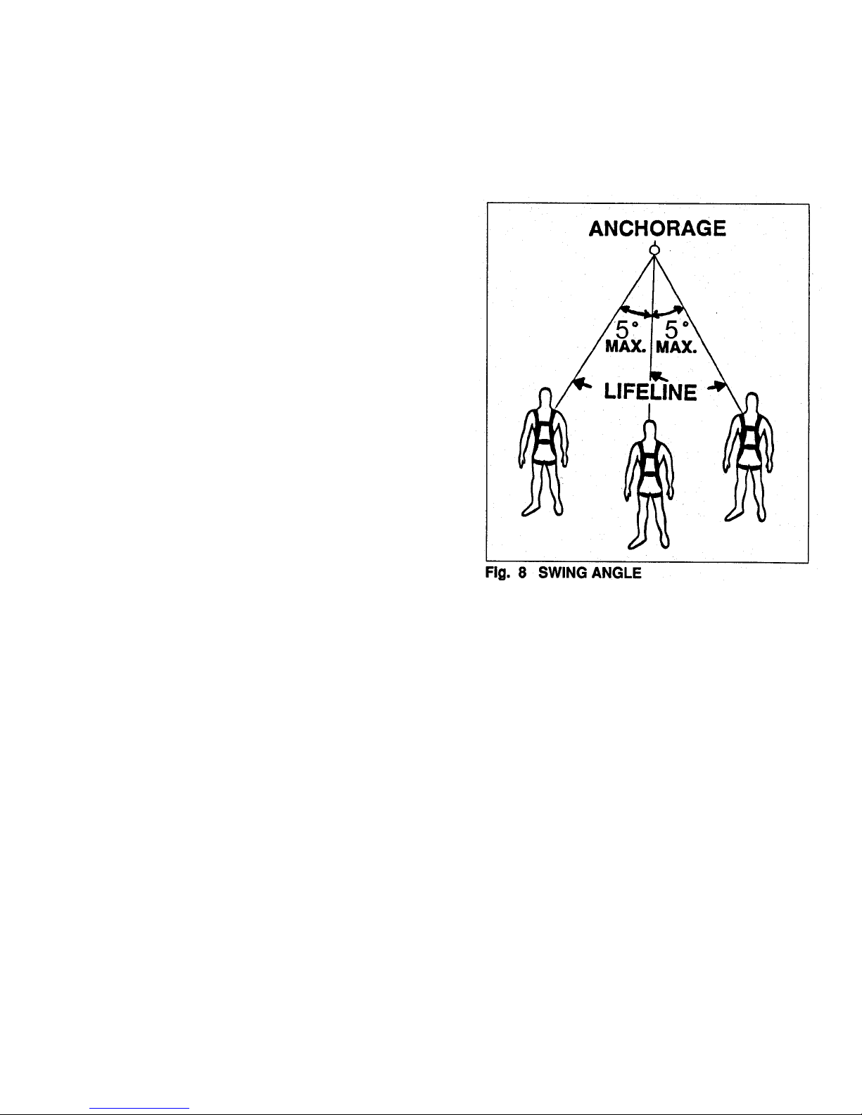
3. Work Support
The winch works well for supporting
workers in a boatswains chair or a full
body harness (single point suspension).
In some applications, a back-up fall
arrest system is also used. In these
applications, a swing angle of less than
5° is recommended. Use only an
approved mounting or anchoring system
at all times. Use only approved
connectors that are equipped with an
anti rollout device.
4. Emergency Rescue
In emergency situations, use the winch
to remove personnel from a hazardous
or an unsafe environment. In these
situations, a back-up fall arrest system
is generally not required. Be sure to use
the proper mounting and anchoring
system for the winch. Use only a fullbody harness for personnel. Always be
aware of the system limitations and
follow the instructions.
5. Limitations
Operators must be aware of several
limitations on the use of the winch
whenever it is used and plan their work
accordingly. Limitations include but are
not limited to:
a. Corrosion:
Do not keep the winch in an area
that has a corrosive atmosphere.
Corrosive vapors can be released
by sewage plants or in fertilizer
plants. Sea water or spray can also
cause corrosion to the case, lifeline
or other components. Long term
exposure to these types of
environment will require more
frequent inspections to insure that
the function of the unit has not been
effected.
b. Chemical or Toxic Environments:
Work environments that contain
strong acids, bases or other
corrosive chemicals in solutions,
sprays or vapors may damage the
winch or auxiliary components.
Inspect the unit frequently to detect
any damage. Chemical damage
may be difficult to detect visually and
periodic lifeline replacement is
recommend to insure safety.
c. Electrical Hazards:
Stay away from power lines or other
components carrying electrical
power. The metal lifeline can
conduct electricity if it gets close to
or contacts a power line or electrified
component. Remember electricity
can jump across an air gap and
electrocute personnel using the
winch. Contact your local utility to
remove or disconnect the power
before working around these
components. Contact Unique
Concepts for synthetic rope options
for reduced conductivity.
Page 12

12
d. Load Capacity:
Do not exceed the winch capacity of
310 lbs. (141 kg) (includes people,
harness, tools etc). Do not carry
more than one person at a time on
the lifeline. Overloading the winch
can exceed the design safety factors
and could create hazards.
e. Training:
Do not allow anyone to use this
winch unless they are trained in its
limitations and use. Untrained
operators can expose themselves
and others to hazards. Train new
operators before using the unit.
Review operating procedures on a
regular basis with experienced
personnel.
3.4 SYSTEM REQUIREMENTS
The Unique Concepts “Basic” Series Winch
is a component in a Confined Space
Entry/Retrieval System. The winch and all
auxiliary components must be compatible to
prevent creating unexpected hazards. A list
of system compatibility requirements
includes but is not limited to:
a. Anchorage
The winch is designed to be attached to
a mounting and support system that
provides the required anchorage
strength.
Anchorage strength requirements are
defined by ANSI and OSHA Standards
or local regulations and must be met to
insure the safety of the entrant. If
Unique Concepts has reviewed and
approved the mounting or anchorage
system, it has sufficient strength to fulfill
the ANSI and OSHA requirements. If
the winch will be used with a non-factory
approved mounting or anchorage
system, a qualified person must review
and approved the application prior to
use.
b. Connectors
Use only approved connectors with
sufficient capacity that have an anti
rollout device designed into the snap.
Non-approved connectors can open
during use and create unexpected
hazards. Do not use them.
c. Personnel Harness
Use only an approved full body harness.
Do not use a single belt or strap system.
Only a full body harness can provide the
required support for the body to prevent
injury.
Page 13

3.5 FIELD OPERATION
13
1. Read, understand and follow the User
Manual and signs on the equipment
before using, maintaining or inspecting
the equipment.
2. Train all operators before allowing them
to use the equipment. An untrained
operator exposes themselves,
bystanders and workers to possible
serious injury or death.
3. Visually inspect the equipment and all
auxiliary components and equipment
before using. Correct any problems
before using the equipment.
4. Securely anchor the winch before using.
5. Use only certified anchor and connector
components in your system.
6. All anchor points, or mounting/setup
locations for permanent or portable
systems must be approved to local
standards by a qualified engineer.
7. Use only an approved body harness for
the workers.
8. Always work in teams. One person
works in the confined space and the
other one pays out the line and reels it
in.
9. Do not use the equipment when the
winch brake wear indicators display in
the red or 1 year in service (which ever
comes first). Return equipment to
manufacturer for service.
10. Do not exceed 310lbs. (141 kg) on the
personal man rated lifeline during
operation.
11. Use only retractable lifelines or shock
absorber with a maximum arrest force
(MAF) equal to or lower than the lowest
rated component of your system.
OPERATING SAFETY
12. Establish a regular training program for
new and experienced workers.
13. Establish a detailed inspection program
for your equipment and document the
findings. Return the equipment to the
manufacturer for rework if any problems
are found.
14. Plan your work program before
starting. Have the required people,
equipment and procedures available to
do the job.
15.
Do not use the equipment around
physical or environmental hazards. This
list includes but is not limited to:
a. Corrosion that may affect the
structural integrity of the life line or
other components .
b. Chemicals which can degrade
components and not be visible.
c. Toxic gases: Rescuers or workers
can be killed in toxic environments.
d. Heat or elevated temperatures.
e. Moving machinery: Workers or
auxiliary equipment can be
contacted by or pulled into moving
components.
f. Sharp edges: Workers or the
rescue equipment can be injured
by or damaged by sharp edges or
components.
g. Electrical hazards: Stay away from
power lines or components carrying
electrical power.
l. Overload: Do not exceed a
personal load capacity of 310 lbs.
(141 kg) or material load capacity
of 620lbs. (282 kg) during
operation.
m. Follow confined space regulations
in Standards.
Page 14

14
The Unique Concepts “Basic” Series Winch
is designed for use in many applications
including but not limited to work positioning,
personnel riding, rescue or confined space
entry/retrieval. It is the responsibility of the
operator to be familiar with and follow all
applicable OSHA and industry standards on
operating guidelines for your project. If you
have any questions, consult with a qualified
person or call the factory.
When using the winch, follow this
procedure:
1. Review and follow the Pre-Operation
Inspection (Refer to Section 3.3).
2. Inspect the unit prior to each use.
Visually check each component to be
sure that there is no damaged or
missing parts. Check that all systems
and components function as intended.
Do not use the equipment if any
problems are found.
3. Working Planning
Plan your entire work project before
starting. Consider all the equipment and
system requirements and comply with
these requirements before starting.
Anticipate the needs before, during and
after the project is being done and
prepare for these needs. Be prepared
for the unexpected by planning in
advance. Your advance planning list
includes but is not limited to:
a. Anchorage
We recommend mounting the winch
to only approved supporting
components and systems to be sure
that the anchorage has sufficient
strength. All support and mounting
systems must be designed to ANSI
and OSHA Standards. Refer to
Structural manual for specific
strengths.
b. Connectors
Connectors if used should be
equipped with an anti-rollout device
to prevent accidental
disengagement. Roll-out can occur
when there is interference between
the connector and load that causes
the gate or keeper to accidentally
open or release. Do not take a
chance with safety. Only use
approved components.
c. Hazards
Stay away from mechanical,
chemical and electrical hazards.
Moving machinery, sharp edges and
other mechanical hazards can injure
personnel, damage equipment or
interfere with the work procedure,
chemical, corrosive or toxic
environments can damage
equipment or affect the well-being or
personnel. Electrical power can
follow through the equipment and
electrocute personnel even if there is
no direct contact. Plan your work or
rescue procedures to consider these
factors and allow for them. Advance
planning will allow the equipment to
be used safely in a variety of
conditions.
d. Cable Path
Body parts, clothing, tools or other
items can get snagged when going
around a corner or over obstacles
during the retrieval procedure.
Corners or sharp edges can also
damage the lifeline as it goes by. Be
prepared to do an entry rescue to
assist in the retrieval of a down
entrant.
e. Vertical Applications
For vertical applications, keep the
swing-fall angle less than 5°.
Serious injuries to personnel can
occur if they swing into a solid
object. Try to keep the entrant
directly below the winch attachment
point at all times. Two people are
required at all times: the entrant and
winch operator. Always maintain
communication to be sure the lifeline
is kept taut and that the entrant is
not encountering problems.
Page 15

15
f. Emergency
During rescue or emergency
procedures, the winch anchorage
must be capable of supporting at
least 1500 lbs. Always use a fullbody harness when moving people.
People can be seriously injured
during rescue or in an emergency
situation if they are not supported in
an approved full body harness.
However quick response is required
in any emergency or rescue
operation.
4. Personal Fall Arrest System
In some entry/retrieval applications,
OSHA and ANSI Standards require that
the entrant be connected to a Personal
Fall Arrest System. It is the
responsibility of the operator to be
aware of these requirements and follow
them. Always use a full body harness
on the entrant when attached to a PFAS
to minimize potential injury to the
entrant. Application limitations for the
winch also apply to a PFAS.
5. Installation/Removal
The “Basic” Series Winch can be
equipped with a universal mounting
base that can mate with mounting
hardware for any support or anchorage
system.
A. Installing
a. Secure attaching hardware to
the universal mounting base.
Refer to appropriate Structure
Manual for bracket mounting
details.
b. Pin crank handle into position by
lining up the holes and pin. Make
sure in is pinned secure before
operating.
c. Refer to Structure Manual for
mounting of winches.
Figure 2 Universal Mounting Base
Figure 3 Crank Handle in collapsed position
Page 16

16
d. Pull on the cable with at least 10
lbs. Force and turn the crank
arm counterclockwise to extend
cable.
Refer to applicable Structure
Manual(s) for cable threading
instructions.
e. Be sure the cable crimps,
thimble, swivel and snap-lock
connector are in good condition
and functioning as intended.
f. Attach the snap hook to the
entrants full body harness.
Figure 4 Cable Extended (Typical)
Figure 5 Snap-lock Connector
Page 17

17
B. Removal:
a. Disconnect the snap hook from
harness. Maintain at least a 10
lb. load on the cable to keep the
cable tight on the spool.
b. Turn the crank handle clockwise
to retract the cable through the
pulley and rollers of the structure
(if applicable) while maintaining
a 10 lb. pull on the cable. See
appropriate structure manual.
c. Retract until copper crimps and
thimble just rolls loosely onto
drum.
d. Remove from mount or
anchorage. Refer to structure
manual for details.
6. Load Attachment
The entrant must be attached to the
winch using the snap hook on the end of
the lifeline. This, and any other
connector, must be equipped with an
anti-rollout device on the gate. When
attaching the entrant, follow this
procedure:
a. Pull on the snap hook with at least
10 lbs. pull while extending the
lifeline until there is sufficient slack
to attach to the entrant.
b. Use two hands when attaching to
the entrant.
c. Use one hand to apply a steady pull
on the lifeline and to steady the snap
hook.
d. Use the other hand to depress the
lock and open the gate.
e. Insert the harness D-ring into the
hook.
IMPORTANT
Always use a full body harness for
personnel and attach to the dorsal
“D” ring.
f. Close gate and be sure the lock
clicks into its locked position.
g. Tighten the lifeline.
h. Reverse the above procedure when
unhooking from the entrant.
Figure 6 Maintaining 10 lbs. on Cable
Figure 7 Snap-lock Connector
Page 18

18
7. System-Integrity
The entrant should always verify the
intergrity of the attachment and system
before entering a confined space. To verify
the integrity of the system, follow this
procedure:
a. Connect the snap hook to the dorsal
ring of the full body harness.
b. Snug up the lifeline.
c. The entrant should slowly lift their feet
off the ground and transfer all the weight
to the lifeline.
d. Be sure the winch holds you in a
stationary position.
e. Be sure the full body harness is
comfortable and does not pinch, chafe
or bind. Adjust for comfort before
starting.
f. Do not enter confined space unless
connectors, brakes, winch and harness
are functioning properly.
8. Crew Personnel
A working crew requires the use of at
least 2 people at all times. The entrant
who is attached to the end of the lifeline
and the attendant who turns the winch
crank and guides the lifeline. Each must
be properly trained in the use of the
equipment and for their task. As the
entrant enters the confined space, the
entrant should maintain communication
with the attendant operating the winch.
Heavy gloves should be worn by the
attendant when guiding the cable. The
two people must work as a team to get
the job done safely and efficiently.
Do not test system
over confined entry.
WARNING
Page 19
19
9. Entering Confined Space
When entering confined space, follow
this procedure:
a. The entrant should move slowly and
smoothly into the confined space
(either vertical or horizontal).
b. The attendant should turn the winch
handle counter-clockwise to pay out
the lifeline.
IMPORTANT
Do not use the winch if turning the
handle clockwise pays out the lifeline.
The internal brakes are engaged only
when the handle operating direction
retrieves the lifeline when the handle is
turned clockwise. The reverse cable
protector should prevent backwards
winding of cable.
c. Wearing gloves, place one hand on
the lifeline to guide it as it extends.
Use your hand to maintain a slight
pull on the cable at all times.
d. For a vertical entry, maintain the swing angle at less than 5
while working. The entrant can be seriously injured if the
swing angle exceeds 5°.
e. If the entrant is not suspended and there is no chance of a
fall, pay out sufficient line (2 ft. max.) so it is slack and the
entrant can work. Hold the lifeline so there is a slight pull
on it at all times.
f. Extend or retract the lifeline as required to keep the line
snug.
g. Maintain communication between the entrant and
attendant at all times. Be sure each knows what the other
is doing.
h. Do not go around corners when entering a confined
space. Body parts, clothing, tools or other items can get
snagged when going around a corner and over obstacles
during retrieval procedure. Corners or sharp edges can
also damage the lifeline as it goes by. Be prepared to do
an entry rescue to assist in the retrieval of a down entrant.
Page 20

prep
i. If the lifeline becomes tight or slack
20
during entry, communicate with the
entrant to determine whether there is a
problem. Correct the problem before
proceeding.
j. The last 10 feet of the lifeline has a
red marker and should not be
unwound from the drum. This
length provide the required wrap on
the drum to properly anchor the
lifeline and insures that the lifeline
wrap direction is correct. Stop
extending the lifeline when you see
the red marker.
10. Retrieving From Confined Space
When exiting from confined space, follow
this procedure:
a. Turn the winch crank arm clockwise to
retract the lifeline and retrieve the
entrant from the confined space.
IMPORTANT
Do not use the winch if turning the
handle counterclockwise retrieves
the lifeline. The internal brakes are
engaged only when the handle
operating direction retrieves the
lifeline when the handle is turned
clockwise.
b. Maintain communication with entrant
when preparing to retrieve and during
the retrieval process.
c. Turn the handle smoothly to maintain an
even retrieval rate.
Figure 9 Cable Marker
d. If the winch handle turning load
increases suddenly, stop and
investigate. Determine the cause and
correct before continuing the retrieval.
Usually this occurrence is caused by the
load catching or snagging on something.
Release the snag before continuing. It
may be necessary to extend the line
slightly to release the snag.
e. Support the entrant or load after
retrieval and disconnect snap hook.
Should the entrant become caught
around a corner or get snagged or
tangled, it may be necessary to enter the
confined space and assist the original
entrant. This should be considered a
new entry or rescue and all regulations
apply to the new entrant. E.g. Lifeline.
Be
CAUTION
ared for a rescue.
Page 21

11. Load Limiter Clutch
21
The winch is designed with a load limiter
clutch that activates when a short free fall
has occurred and while brakes are
engaged. The clutch will slow the fall
gradually until it comes to a complete stop.
There must be at least 10 feet of cable on
the drum at all times for this clutch to be
effective.
When activation of the load limiter clutch
occurs, the operator can still extend or
retract the cable from its stopped position by
turning the crank. When the entrant is out,
remove the winch from service and return to
the factory for rework.
12. Rescue or Emergencies
The winch is designed for entry and retrieval
of people from confined spaces in rescue or
emergency applications. Although fast
response is crucial for saving lives, it is still
necessary to be aware of and follow all
safety and operating procedures. Do not
take chances with shortcuts. Peoples lives
are at stake. Use only trained competent
people who know the equipment and can
safely rescue people from an emergency
situation.
Figure 10 Load Limiter Clutch Indicator Window
Page 22

13. Operating Hints
22
a. Follow all applicable OHSA and ANSI
Standards and local regulations when
using this equipment.
b. Train all new operators before allowing
them to use the equipment. Conduct
regular refresher training sessions with
all experienced operators.
c. Inspect and maintain the equipment on
a regular basis. Remove defective
equipment from service. Keep
inspection and maintenance records.
d. It is recommended that the winch be
used in conjunction with other approved
components and systems. Approved
components and systems have the
required function, strength and
compatibility for all applications.
e. Review and follow the limitations for the
equipment. Do not use in corrosive
conditions, toxic atmosphere or around
mechanical or electrical hazards without
taking special precautions.
f. Plan your project before starting to work.
Anticipate all the normal and
unexpected needs relating to equipment
and procedures and have them at hand
before starting. Advance planning can
save time and lives.
g. An entrant and attendant must work as
a team. Maintain communication at
all times.
h. Check the condition of the brake wear
each time the winch is used. When the
indicator moves into the red portion of
the scale or 1 year in service (which
ever comes first), remove from service
and return to the factory for service.
i. Use Loctite 262 (or equivalent thread
locker) to secure crank handle anchor
bolts if required, Figure 11. Secure
them if they come loose during use.
Brake Wear Indicator Window
Expiration Date, has to be recertified
Figure 11 Winch Safety Features
Figure 12 Handle Anchor Bolts
Page 23

3.6 STORAGE
23
Prior to storage, the winch should be
thoroughly inspected and maintained.
Return winch for repair or replacement
of any worn or damaged components to
prevent any unnecessary down time at
the next use. Follow this procedure:
1. Thoroughly clean the winch using
mild soap on the body and labels.
Be sure the labels are legible.
2. Use a neutralizing solution to clean
lifeline. This is particularly important
if the unit had been used in corrosive
or toxic environments.
3. Perform a complete inspection of the
unit and document the results.
4. Touch up all nicks and scratches to
prevent corrosion.
5. Store in a cool dry place.
Page 24

24
9. Entering Confined Space
When entering confined space, follow
this procedure:
a. The entrant should move slowly and
smoothly into the confined space
(either vertical or horizontal).
b. The attendant should turn the winch
handle counter-clockwise to pay out
the lifeline.
IMPORTANT
Do not use the winch if turning the
handle clockwise pays out the lifeline.
The internal brakes are engaged only
when the handle operating direction
retrieves the lifeline when the handle is
turned clockwise. The reverse cable
protector should prevent backwards
winding of cable.
c. Wearing gloves, place one hand on
the lifeline to guide it as it extends.
Use your hand to maintain a slight
pull on the cable at all times.
d. For a vertical entry, maintain the swing angle at less than 5
while working. The entrant can be seriously injured if the
swing angle exceeds 5°.
e. If the entrant is not suspended and there is no chance of a
fall, pay out sufficient line (2 ft. max.) so it is slack and the
entrant can work. Hold the lifeline so there is a slight pull
on it at all times.
f. Extend or retract the lifeline as required to keep the line
snug.
g. Maintain communication between the entrant and
attendant at all times. Be sure each knows what the other
is doing.
h. Do not go around corners when entering a confined
space. Body parts, clothing, tools or other items can get
snagged when going around a corner and over obstacles
during retrieval procedure. Corners or sharp edges can
also damage the lifeline as it goes by. Be prepared to do
an entry rescue to assist in the retrieval of a down entrant.
Page 25

25
Weekly
1. Functional Inspection
Perform a functional inspection. Refer to
Section 4.2.2. Record results and keep
documentation.
AS REQUIRED
A) Lubricate the Cable
Use a light oil to lubricate the cable.
Lubricating oil should only be applied to
a clean dry cable. Use a stiff bristled
brush to remove contaminants from the
cable if it is dirty. Allow the oil to
penetrate into the cable to reduce
internal friction. Wipe the cable dry with
a clean cloth as it is being retracted into
the winch.
B) Clean Winch
Use a damp cloth and mild soap to
clean the body components and labels
of dirt and residue. Be sure labels are
legible.
C) Complete Inspection
Perform a complete inspection. Refer to
Section 4.2.3. Record results and keep
documentation.
Annually
This winch must be returned to the
manufacturer annually to be re-certified for
continued use.
All risk of personal injury, death or property
damage occurring after the expiration date
shown shall be completely assumed by the
user, and the user releases Unique Concepts
Ltd., its employees and agents, from all liability
for any such personal injury, death or property
damage occurring after the expiration date
shown.
Expiration date is indicated on the winch crank
arm.
Figure 14 Cable Oiling
Page 26

26
4.2 INSPECTION
4.2.1 Visual Inspection
A complete visual inspection should be
performed on the system you are using prior to
the operation. The following items should be
checked; and the results recorded on the
“Inspection Log” sheet (see Section 4.2.5).
1. Labels
Check that all labels are clean and legible.
Clean the labels if any are dirty using a mild
soap and a damp cloth. Replace if any are
illegible (Refer to Section 5 for a listing of all
labels).
2. Fasteners
Check that all screws and other fasteners
are tight. If any are loose or missing,
contact your local dealer or the
manufacturer.
3. Structural Components
Check the components for cracks, dents,
bends, or breaks. Minor cosmetic damage
in the component body will not affect the
function of the davit system. However if
there are major dents or any other structural
damage, the unit should be removed form
service and returned to the manufacturer for
service.
4. Corrosion
Check all components for damage from
corrosion. Although all components resist
corrosion, working in corrosive
environments can lead to damage. Inspect
all structural components and fasteners for
signs of damage. If damage found, remove
from service and return to the manufacturer
for service.
Figure 15 Labels
Instruction Plate Side
Crank / Cover Side
Page 27

27
5. Crank Arm
Check that each handle on the crank arm is
tight. Use Loctite 262 (or equivalent thread
locker) on the anchor screw if required to deep
them tight. Check that the crank arm slides
easily into each drive pocket and that it locks
securely in place. If the crank arm is bent,
damaged or does not fit and lock into the drive
pockets, remove arm and replace. Do not use
crank arm unless it is fully functional.
6. Connectors
Check the cable collar and clamp for signs of
wear, distortion or cable fraying. Remove from
service and return to the factory for service if
any problems are found. Check the gate and
gate lock on the snap hook. Both must open
and close easily. If they do not, remove from
service and return to the factory for service.
7. Brake Indicator and Expiration
Check the condition of the brake indicator and
annual re-certification date. The indicator
should be in the green. If the window shows in
the red or a combination of green/red, remove
from service and return to the factory for
service. If the expiration date exceeds 1 year in
service, remove form service and return to the
factory for service.
Figure 16 Handle Anchor Bolts
Figure 17 Snap-lock Connector
Brake Wear Indicator Window
Expiration Date, has to be recertified
Figure 18 Winch Safety Features
Page 28

4.2.2 Functional Inspection
28
A functional check should be performed on
the winch prior to every use. The following
functional tests should be done:
1. Winch Crank Rotation Direction
The winch crank must turn in the
clockwise direction to retract the lifeline
and counterclockwise to extend for the
internal brakes to engage properly. If
the crank direction is reversed, the
lifeline must be extended completely
(including the last 10 feet past the
plastic coated red mark) to remove all
the cable from the spool. In this
procedure, turning the crank clockwise
will extend the cable. Always keep a 10
lb. pull on the cable clockwise until the
cable stops extending and starts
retracting. Maintain the 10 lb. tension
on the line until the cable is completely
retracted. If the cable has been
reversed on the spool, the cable may
have been damaged. Inspect the cable
as in Section 4.2.3.
2. Snap Hook
Manually check that the swivel on the
top of the snap hook turns easily without
sticking or binding. Also check that the
gate locks and the gate opens and
closes easily without binding and
sticking. If any component sticks or
binds, lubricate with a light oil. If
sticking or binding persists, remove
winch from service and return to the
factory for service.
3. Brake Engagement
The internal brake must hold the cable
from extending or retracting unless the
crank arm is turned. To functionally
check this required feature, extend the
cable in 10 foot increments by turning
the crank counterclockwise. Then pull
sharply on the cable to be sure the
brakes hold securely. If they do not
hold, remove the winch from service and
return to the factory for service.
4. Brake Ratchet Mechanism
The winch is designed with an internal
ratchet that engages the brake
continuously when the crank arm is
turned. The ratchet should be making a
clicking sound when the crank is turned.
This ensures the spring-loaded pawls
are continuously engaging the ratchet. If
ratchet clicking is not heard when the
crank is turned, remove from service
and return to the factory for service.
A
B
a Retrieval Clockwise
b Extension Counter-Clockwise
Figure 19 Crank Rotation
Page 29
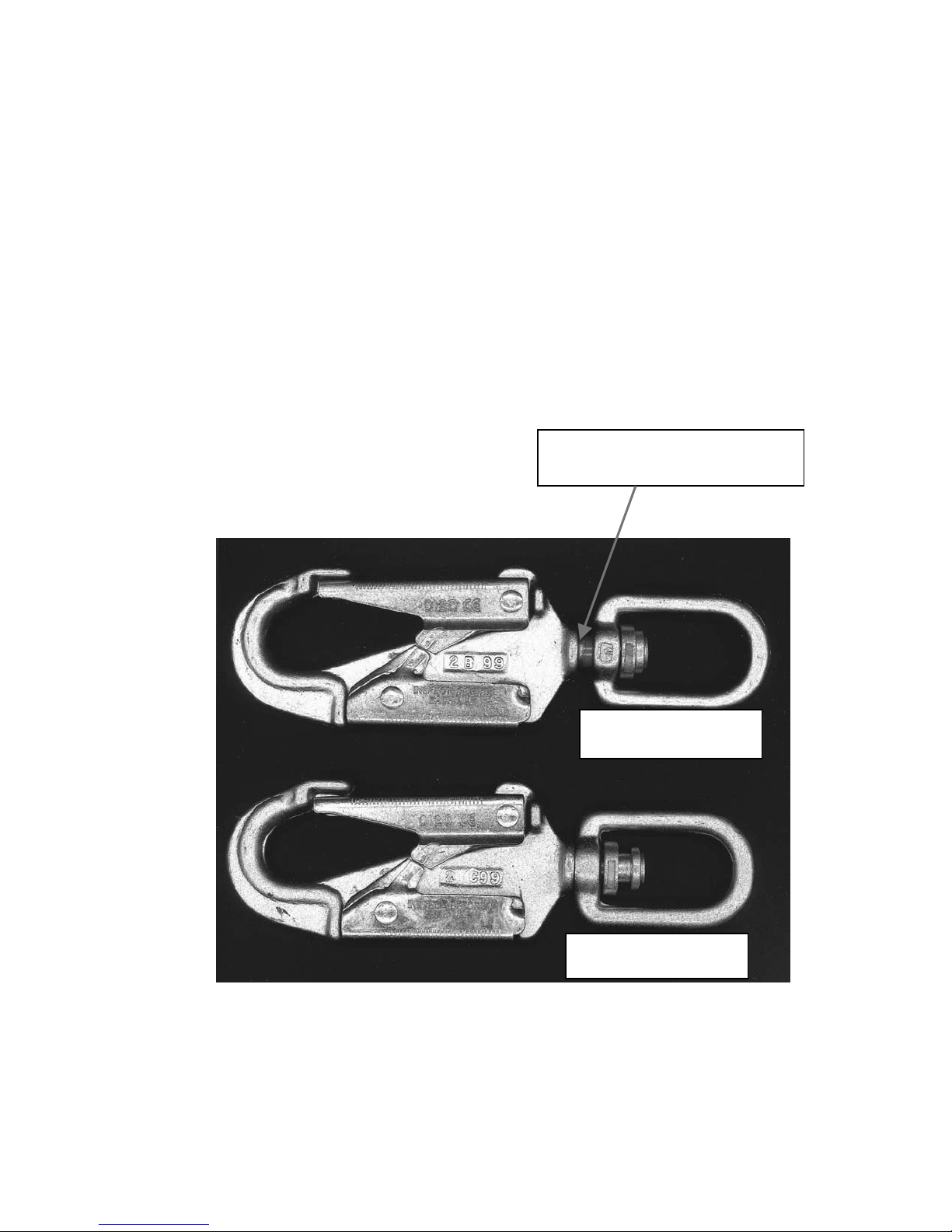
3.con’t
29
Starting in September of 2000, new
UCL Safety Systems Lifeline assemblies will
incorporate a double-locking swivel snap with a
built in overload indicator. These snaps are
designed to visually identify lifeline assemblies
that have been subjected to loading in excess
of double the winch’s rated working load limit of
310 lbs.
Any winch on which the overload indicator has
been activated must be removed from service
immediately and inspection, repair, and recertification.
All warranties and liabilities shall be void for
winches on which the overload indicator has
been activated.
Exposed Red Overload
Indicator
Activated Snap
Indicator
Un-Activated Snap
Indicator
Figure 20 Load Indicator Double Locking Snap
Page 30

4.2.3 Detailed Inspection
30
A detailed inspection should be done at
the manufacturers winch factory on the
winch every year. The inspection must
include the following, results logged on
the sample inspection form and retained
in your files should anyone ask to see
them. Refer to Section 4.2.6 for a
sample inspection form.
The detailed inspection should include:
1. Visual Inspection
Refer to Section 4.2.1 for a listing of all
times that should be checked visually.
Log the results on the inspection form.
2. Functional Inspection
Refer to Section 4.2.2 for listing of all
items that should be functionally
checked. Log the results on the
inspection form.
3. Detailed Inspection
a. Cable Fittings/Snap Hook
Check the cable fittings on the end
of the lifeline. Be sure that it is not
cracked, distorted, bent, corroded,
worn, loose or cutting into the cable.
Be sure that the cable clamp is tight
without signs of wear of corrosion.
Be sure the cable and strands are
not frayed or broken.
Check the snap hook. Be sure it is
not bent, distorted, cracked or worn.
Be sure the swivel turns freely and
the gate locks and the gate opens
and closes easily.
Note results on inspection log.
b. Cable Inspection
The cable must be inspected over its
full length and the results recorded
in the inspection log. Always wear
heavy gloves to prevent cuts and
slivers while handling the cable. If
any strands are broken, remove
from service.
Figure 21 Cable Fittings/Snap Hook
Figure 22 Cable Definitions
Page 31

i. Check for broken wires
31
Pull the cable out in small segments
and flex to check for broken wires.
NOTE
The inspection of the cable is all
based on the definition of a lay, core,
strand and wire. A lay is where a
strand makes one complete
revolution around the core. The
core is the center of the cable itself.
A strand is the bundle of wires that
move around the core. A wire is a
single filament that makes up a
strand.
Start the inspection at the cable
clamp to check for broken wires or
strands. Pull out a short segment of
cable and turn it while flexing to
check for broken wires.
IMPORTMANT
Review the cable inspection log to
determine the location of previously
found broken wires or other defects.
These previously found defects
combined with those found during
this inspection may require that the
winch be removed from service.
Inspect the entire length of the cable
logging the results on the inspection
form.
When a broken wire is found,
remove the protruding end by flexing
it back and forth along the length of
the cable. The wire will normally
break off inside the cable so there
are no exposed ends to damage
adjacent strands. Do not pull on an
end or wire with pliers. It can pull
the broken end out to expose it.
Figure 23 Broken Wire
Page 32

Use the previous inspection logs to
32
determine the total number of
broken wires in a lay. Remove the
cable and winch from service when:
• There are three or more
randomly distributed broken
wires in one cable lay.
• There are two or more broken
wires in one strand in one lay.
• There are any broken wires
within 1.0 inches (25 mm) of the
cable clamps next to the thimble.
Return the winch to the factory for
cable replacement if any of these
conditions are met or exceeded.
ii. Worn or Abraded Wires
Check for worn or abraded wires.
Worn or abraded wires are caused
by friction and rubbing against
adjacent components and are
usually brighter in appearance.
Remove from service if any surface
wires in one area are worn by 1/3 or
more of their diameter.
Figure 24 Cable Inspection
iii. Bulges or Reduction in
Diameter
Check for bulges or a reduction of
the cable diameter. When these
conditions occur, it indicates serious
internal cable damage. Remove the
unit from service when the cable
diameter increases or decreases by
0.05 inches (1.3 mm).
Figure 25 Cable Diameter
ASSESS
Page 33

33
iv. Corrosion:
Check for corrosion. Corrosion can
be seen as a discoloration of the
wires in most cases. Although there
is no simple sure way to tell when
corrosion has excessively weakened
the cable, the inspection personnel
must keep in mind that corrosion
normally develops on the inside of
the cable before it becomes visible
on the outside. Have a qualified
person assess the damage and
determine whether the unit should
be removed from service. Pitting is
a particularly serious sign of
advanced corrosion. Rust along
with broken wires in a given area is
sufficient reason to remove the unit
from service.
v. Insufficient Lubrication
Check for insufficient lubrication of
the cable. Generally this is caused
by a build-up of contamination
between the strands of cable.
Packed grease, dirt, paint or other
contaminants prevents the lubricant
from getting inside the cable to
prevent internal friction and
corrosion. If contaminants have
filled the grooves, remove from
service.
vi. Snagged Wires and
Crushed or Flattened
Strands
Check for snagged wires and
crushed or flattened strands. These
conditions appear when the cable
has been pulled around corners or
caught between two heavy objects.
Remove from service and return to
the factory for rework.
Figure 26 Crushed Cable
Page 34

vii. Unlaying and Bird-Caging
34
Check for unlaying and bird-caging
of strands. This condition appears
as the formation of gaps, loops and
excessive clearance between
strands. If this appears, remove the
unit from service and return to the
factory for rework.
viii. Kinks and Bends
Check for kinks and bends in the
cable. Kinks and bends are created
when a loop forms in a slack cable
and then it is pulled tight without the
loop uncoiling. Remove from
service if kinks or bends are formed
in the cable.
ix. Heat Damage, Torch Burns
or Electric Arcs
Check for examples of heat damage,
torch burns or electric arc strikes.
Localized discoloration, fusing or
melting indicate this type of damage.
If this is found, remove the unit from
service and return to the factory for
service.
Figure 27 Cable Separation
Figure 28 Cable Damage
Page 35

35
4.2.5 Inspection Log
4.2.5.1 Winch Inspection Log
Sample form. Copy page to start inspection log record book. Fill out using ball point pen.
Model No.: Serial No.: Annual Re-Certification Date:
Date of Inspection
Counter Number
Inspector
FUNCTION
WINCH BODY
SNAP HOOK
Extension (CCW)
Retraction (CW)
Brakes
Fasteners
Labels
Brake Pointer
Damage
Corrosion
Cable Collars
Handle(s)
Damage/Wear
Corrosion
Swivel
Gate Lock
Gate
Cable Clamp
Note: If the brake indicator points into the red or the winch is in service for 1 year, (which ever comes first),
return to manufacturer for inspection and service.
Page 36

36
4.2.5 INSPECTION LOG (con't)
4.2.5.2 WINCH CABLE INSPECTION LOG
Sample Form. Copy page to start inspection log record book. Fill out using ball point pen.
Model No. Serial No. Mfg. Date:
Cable
Location*
Measured
Diameter
Broken Wires At Fittings
In 1 Strand
In 1 Lay
of 1 Lay
Corrosion
Excess
Wear
Broken
Wires Corrosion
Lubrication
* Note: Measure location from snap hook.
Page 37

5 LABELS
37
5.1 Warning Labels
The types of labels and locations on the
equipment are shown in the illustration
below. Good safety requires that you
familiarize yourself with the various
LABELS, the type of warning and the area,
or particular function related to that area,
that requires you SAFETY AWARENESS.
Think SAFETY! Work SAFELY!
Instruction Plate Side
Crank / Cover Side
Figure 29 Labels
Page 38

38
Page 39

39
Page 40

Certificate No. FM 39709
ISO
9001
A Capital Safety Company
40
CSG USA & Latin America
3833 SALA Way
Red Wing, MN 55066-5005
Toll Free: 800.328.6146
Phone: 651.388.8282
Fax: 651.388.5065
solutions@capitalsafety.com
CSG EMEA
(Europe, Middle East, Africa)
Le Broc Center
Z.I. 1ère Avenue
5600 M B.P. 15 06511
Carros
Le Broc Cedex
France
Phone: + 33 4 97 10 00 10
Fax: + 33 4 93 08 79 70
information@capitalsafety.com
CSG Canada
260 Export Boulevard
Mississauga, ON L5S 1Y9
Phone: 905.795.9333
Toll-Free: 800.387.7484
Fax: 888.387.7484
info.ca@capitalsafety.com
CSG Australia & New Zealand
20 Fariola Street
Silverwater
Sydney NSW 2128
AUSTRALIA
Phone: +(61) 2 9748 0335
Toll-Free : 1 800 245 002 (AUS)
Toll-Free : 0800 212 505 (NZ)
Fax: +(61) 2 9748 0336
sales@capitalsafety.com.au
www.capitalsafety.com
CSG Northern Europe
Unit 7 Christleton Court
Manor Park
Runcorn
Cheshire, WA7 1ST
Phone: + 44 (0)1928 571324
Fax: + 44 (0)1928 571325
csgne@capitalsafety.com
CSG Asia
Singapore:
16S, Enterprise Road
Singapore 627666
Phone: +65 - 65587758
Fax: +65 - 65587058
inquiry@capitalsafety.com
Shanghai:
Rm 1406, China Venturetech Plaza
819 Nan Jing Xi Rd,
Shanghai 200041, P R China
Phone: +86 21 62539050
Fax: +86 21 62539060
 Loading...