

Page 1

Anchor on the Go™
Portable Roof Anchor for Metal Roofs
Part Number 762998
Patent Number 2003258383
Installation and Operating
Instructions
WARNING: This product is part of a fall protection system. Users must read and
follow instructions in this guideline for each component of the complete system.
Manufacturer’s instructions must be followed for correct care, use and maintenance
of this product. Alterations or misuse of this product, or failure to follow instructions
may result in serious injury or death. Reading this manual of itself does not
constitute competency based training in the use of fall arrest products or systems.
Page 2

CONTENTS
Topic Page
General Use Warnings 3
1.0 Introduction 3
1.1 Anchor design and application 4
1.2 Strength of supporting structures 5
1.3 Recommendations 5
1.4 Assessing Fall Hazards 6
1.5 Swing Fall 6
2.0 Installation 7
2.1 Installing Anchor on the Go™ on the roof 7
2.2 Removal of Anchor on the Go™ 10
3.0 Provision of Personal Protective Equipment 10
3.1 Types of PPE 10
4.0 Using Anchor on the Go
equipment and warnings 11
5.0 Standards Compliance 14
5.1 Inspection, care and maintenance 14
5.2 Training in the use of fall arrest systems 14
5.3 Supervision of the use of fall arrest systems 15
6.0 Schematic drawings of anchor 15
7.0 Inspection and maintenance log 17
™ with fall protection
2
Page 3

GENERAL USE WARNINGS
VISUALLY INSPECT TEMPORARY ANCHOR PRIOR TO, AND
FOLLOWING EACH USE, TO ENSURE IT IS IN A SERVICEABLE
CONDITION (refer to section 5.1). IF IN DOUBT, REMOVE FROM
SERVICE IMMEDIATELY.
INSTALLATION AND USE OF THIS PORTABLE ROOF ANCHOR
MUST BE PERFORMED BY, OR UNDER THE SUPERVISION OF A
COMPETENT PERSON.
DO NOT ATTACH OR USE TEMPORARY ROOF ANCHOR WITHOUT
FIRST READING, UNDERSTANDING & FOLLOWING THESE
INSTRUCTIONS.
DO NOT USE THE PORTABLE ANCHOR FOR ANY PURPOSE OTHER
THAN FOR WHICH IT HAS BEEN DESIGNED.
PRIOR TO COMMENCEMENT OF WORK, PLEASE ENSURE THAT
YOU HAVE READ AND COMPREHENDED THE DETAIL REFERRING
TO POSITIONING OF THE ANCHOR AND THE APPROPRIATE SAFE
WORK AREA.
THIS TEMPORARY ANCHOR POINT MUST BE SUBJECTED TO A
DOCUMENTED INSPECTION EVERY 12 MONTHS BY A COMPETENT
PERSON.
1.0 INTRODUCTION
This is a Temporary Anchorage device that has been designed as a
component of a personal fall arrest system and is for use only where
there are no other practical means of connection or work practice.
Relevant State or national legislation may impose obligations to provide
safe systems of work. To discharge these responsibilities, conduct hazard
identication and risk assessment with reference to the hierarchy of
control of risks. Refer to your local State or Federal guidelines or Code of
Practice for safe work on roofs for more details.
Anchors must be properly installed prior to the operator attaching to
them and then used according to requirements contained in this manual.
3
Page 4

1.1 Anchor Design and Application
The Anchor on the Go™ Portable Roof Anchor for Metal Roofs has been
designed and tested to 15kN and is therefore rated as a single person fall
arrest anchor under AS/NZS1891.4. It is only suitable for use on roofs
constructed with metal roof sheeting with a minimum BMT of 0.42mm
in the following proles – Custom Orb, Trimdek, Spandek and Klip-Lok
406 & Klip-Lok 700 provided ridge-capping is secured in place with roof
screws per manufacturer’s instructions.
IMPORTANT: The Anchor on the Go™ Portable Roof Anchor is NOT
suitable for tiled, shingled, aluminium sheet, asbestos or decramastic
roofs.
IMPORTANT: This anchor is designed to be attached to the opposite
side of the roof from where you intend to work. Do NOT connect to or use
the anchor on the same side of the roof where the anchor is connected.
If a second person is required to work on the roof, a second anchor
device must be used. Connecting two lines to a single anchorage device is
NOT permitted. Where two connecting devices are attached to the same
anchorage point (e.g. two snap hooks), the snap hooks may rub against
each other, causing them to be entangled or even become disengaged
from the anchorage device.
Additionally, testing has concluded that whilst this device can sustain a
load of 22kN, the roof sheeting proles most commonly used in Australia
and New Zealand will not sustain a static load greater than 15kN.
IMPORTANT: Do NOT work outside an arc of 30 degrees either side of
the centre line of the anchorage location to reduce the danger of swing
fall hazards - refer to Figure One over the page.
The user of this Anchor on the Go™ Portable Roof Anchor shall be
trained and ensure that care is taken to adjust the safety line length so
that he/she will not be able to fall off the ends of the roof.
IMPORTANT: Anchor on the Go™ Portable Roof Anchor is NOT suitable
for use as an anchorage device for a Temporary Horizontal Life Line.
4
Page 5
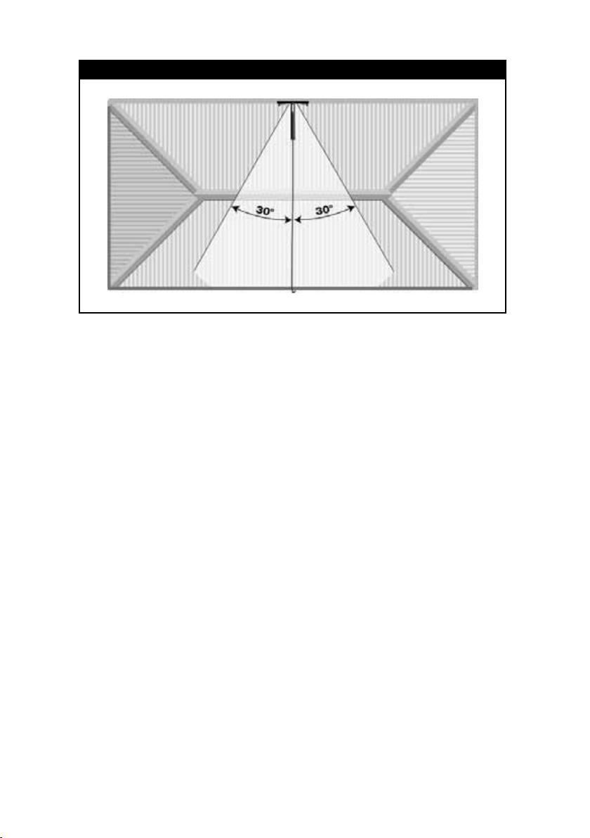
Figure One
1.2 Strength of Supporting Structures
If it is unclear to the operator or competent person that the roof sheeting
or structure is adequate, the roof sheeting or structure shall be assessed
by an engineer. It is NOT SAFE to climb onto the roof on the same side
as you have attached the anchor or use it when connected to the same
side.
The supporting structure/ roof sheeting should be capable of sustaining
an ultimate load equal to 15kN for single point connection as per
AS/NZS1891.4.
1.3 Recommendations
Employers, Supervisors and Operators should ensure that:
• Locations of anchors comply with the requirements for safe use, safe
access, the pendulum effect, as stipulated in AS/NZS 1891.4 clause
3.2.
• Structural supports for anchors are assessed separately by a suitably
qualied engineer (as stipulated in AS/NZS 1891.4, clause 3.1.2.)
or by a competent person, as appropriate, and the assessment
documented.
• Anchors are inspected for compliance with the requirements in
AS/NZS 1891.4 clause 9.3.3 and the inspection documented. The
5
Page 6

documentation should specify any ongoing requirement to carry out
testing of anchor points.
• Anchors are properly labelled and instructions for safe use and
appropriate installation plans are supplied to the user.
• ALL operators must be competently trained for safe work at height
prior to commencing any activities as per AS/NZS 1891.4.
1.4 Assessing Fall Hazards
Employers must ensure that any task an employee is required to
undertake on a roof, that any potential fall hazard is identied, such as:
• from an unprotected edge;
• from an unsecured or inappropriately xed ladder or scaffold;
• slipping on a wet or steep pitched roof(caused by inclement weather
or inappropriate footwear);
• accessing varying roof levels;
• through a fragile roof;
• through a ceiling, skylight or vent;
• being blown or knocked over the edge of a roof.
All such hazards should be identied in the risk assessment process and
documented with relevant precautions to be taken to avoid personal
injury in advance of any work taking place.
1.5 Swing Fall
Figure Two
Operators should ensure they
do not subject themselves to a
common hazard known as swing
fall, refer to Figure Two. Precautions
to avoid this hazard include
removing working slack from the
rope working line, using restraint
techniques and ensuring the person
does not approach a leading edge
such they may be subjected to an
unplanned fall.
6
Page 7

2.0 INSTALLATION
2.1 Installing Anchor on the Go™ on the roof
Step 1: Plan and prepare for the work to be undertaken. Complete a risk
analysis of the site to determine all the potential hazards. Consideration
should be given to work method statements, safe access, roof structure/
sheeting integrity, rescue procedure and so on.
Step 2: Inspect all equipment (Anchor on the Go™, Harness and any
associated Safety Equipment) prior to use to ensure it is within operating
period and is t for purpose, free of damage etc. This process should
include a thorough inspection of structure to which the Anchor on the
Go™ will be installed. Refer to section 5.1 for inspection, care and
maintenance details.
Step 3: A safe means to access the intended temporary anchor installation
shall be provided.
Access to the roof will generally be by scaffold or ladder systems.
Scaffolding may only be erected, moved or disassembled by a competent
person and fall protection principles must be followed in those processes.
Further information can be obtained from AS/NZS 4576 Guidelines for
Scaffolding.
Where access is by ladder systems, the following items should be
checked:
• Inspect the ladder rungs and rails for any defects, cracks or corrosion.
• Never use a ladder with split or missing rungs or with oil or other
slippery material on the rungs.
• The ladder should be tted with non slip feet.
• Place the ladder at a slope of 4 to 1, and secure at both the top and
bottom.
• Ascend and descend facing the ladder with both hands free to hold
the ladder.
• Always keep the area near the top and bottom of the ladder clear.
• Ladder side rails must extend 1m above the landing surface and be
7
Page 8
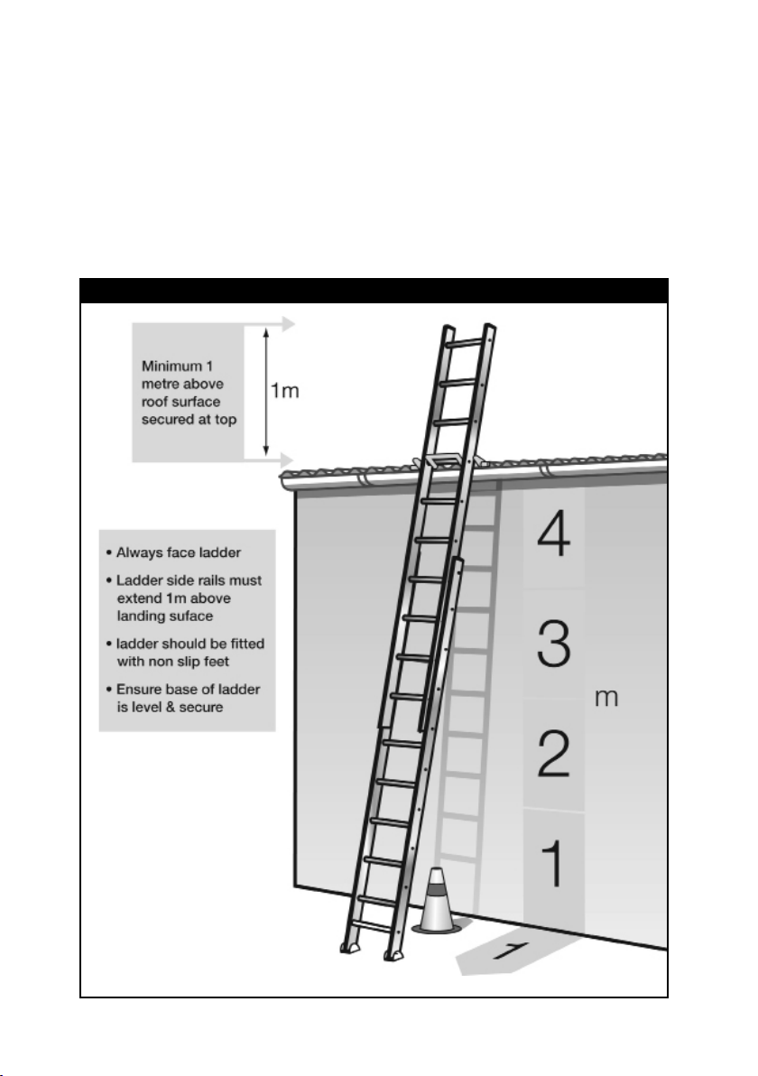
secured at the top to prevent slipping.
Further information can be obtained from AS/NZS 1892.1 Portable
Ladders Part 5: Selection, Safe Use and Care.
Safely position a portable ladder close to the roof location where the
temporary anchor is to be located. Ensure the ladder is securely fastened
to the building to remove the risk of a fall from the ladder - refer to
Figure Three.
Figure Three
8
Page 9

WARNING: If it is unclear to the operator or competent person that the
supporting structure, roof sheeting or anchor is structurally inadequate,
they must be assessed by an engineer.
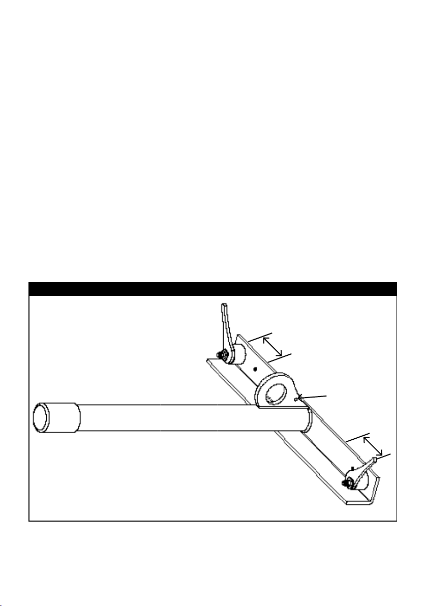
Step 4: Once you have safely ascended the ladder, slide the bottom
angle iron of the portable roof anchor under the roof sheeting. The
cylindrical support post must rest in the pan of the roof sheeting. Both
locking cam levers must also be located within the roof sheeting pans.
If they do not t within the pan, reposition the locking cams into an
alternative adjustment position along the L-angle until they do. Note:
When adjusting the position of the locking levers, ensure left and right
levers are correctly installed. Refer to section 6, Figure Eight a & b for
correct orientation.
Figure Four
Step 5: Securely push down
locking cam levers onto roof
sheeting to achieve a solid
connection. Once the anchor is
attached and your anchorage
line is secured to the anchor
point, throw the rope over
to the other side of the roof
such that the anchor line is
accessible without climbing
onto the roof. Refer to Figure
Five.
Figure Five
9
Page 10

Step 6: Return to the ground and walk to the other side of the roof and
connect the rope grab on the anchorage line to the fall arrest connection
point on your full body harness. Capital Safety always recommends that
a shock absorber be used between the rope grab and the connection
point to reduce the risk of injury in a fall.
NOTE: A second Anchor on the Go™ device can be installed on the
opposite side of the roof to enable the operator to work on both sides of
the roof and be connected between them with two separate rope lines.
This is called Restraint Technique.
2.2 Removal of Anchor on the Go™
After descending the roof from the access side and disconnecting from
the anchor line, then climb the ladder you have placed (safely) close to
the temporarily installed anchor and simply reverse the process used for
installation.
3.0 PROVISION OF PPE
Before commencing work on roofs, the contractors doing the work should
assess all foreseeable conditions likely to affect the health and safety of
the employees or themselves, as identied during the risk assessment
procedure, and arrange for the provision and use of appropriate Personal
Protective Equipment (PPE). If alternative means of access can be
arranged safely without the need for PPE, these methods should be
adopted rst if deemed practical.
3.1 Types of PPE
The following are examples of PPE often associated with roof work.
Appropriate PPE, whether listed below or not, should be provided when
required:
• Fall arrest equipment should be selected to protect the wearer and
allow them access to the areas they need to work, maintaining
freedom of movement and be comfortable;
• Footwear to reduce the risk of falls resulting from slips - rubber soled
shoes with herring bone or similar nonslip tread pattern are commonly
selected;
• Eye protection to reduce the risk of eye injury - eye protection
10
Page 11

complying with AS1337 Eye protectors for industrial applications
should be provided and used;
• Protection from sun, workers should be protected from sunlight/UV
radiation by using a sunscreen with a sun protection factor (SPF)
rating of at least 30+ and by wearing hats, shirts with long sleeves
and long trousers.
4.0 USING THE ANCHOR ON THE GO™ WITH FALL
ARREST EQUIPMENT.
The anchor should be tted in accordance with the manufacturer’s
instructions (Section 2.0) at the edge of the non working side of the roof.
Step 1: The operator should inspect and don a fall arrest rated harness
tted with a frontal fall arrest point and adjust it to ensure it is correctly
tted and comfortable. Capital Safety always recommends that a shock
absorber be used between the rope grab and the connection point to
reduce the risk of injury in a fall. The rear (dorsal) fall arrest connection
point is also deemed an appropriate connection point however its
selection/use will depend on the type of work being completed.
Step 2: Once the Anchor on the Go™ is installed as per instructions in
Section 2.0, ensure the rope is of sufcient length to hang two metres
past the proposed connection point on the alternative side of the roof
in order to facilitate attachment to a fall arrest attachment point prior
to leaving the ladder or scaffold. The rope should be pulled tight and
tensioned to ensure all slack has been taken up before connection. If the
rope grab is already on the rope, ensure it is positioned at the free end.
Step 3: The roof should then be accessed from the working side, the
operator connecting the rope grab to the rope (or accessing the rope
grab permanently attached to the rope) and the shock absorber to the
rope grab before moving from the ladder or scaffold onto the roof.
Step 4: To minimise the fall distance resulting from any slip or fall, it is
important to have the least amount of slack on the line at any point in
time. This means regular and small adjustments of the rope grab up and
down the rope in line with the required movement on the roof. Refer to
Figure Six over the page.
When moving up the roof, the manual rope grab should be opened and
11
Page 12

slid up the rope as much as an arm’s
length. It should immediately be
Figure Six
released to lock the rope grab onto
the rope. The worker should climb
towards the rope grab and repeat the
movement until the work position has
been reached.
When moving down the roof, the
worker should move down until the
rope is taught, then release and
move the rope grab towards the
body, releasing it to again provide an
anchor. When the work position has
been reached, the rope grab should be
released and run up the rope toward
the roof ridge to remove as much
slack as possible.
By removing the working slack from the system, the person reduces the
risk of swing fall, lessens overall fall distance and reduces possible fall
distance in the event the roof surface gives way, allowing the person to
fall through.
GENERAL OPERATIONAL WARNINGS – SAFE WORK AREA
When traversing the roof, the same procedure should be followed
and should be set up such that the system operator will be
prevented from reaching an unprotected edge.
The operator of the Anchor on the Go™ Portable Roof Anchor
shall be trained and ensure that care is taken to adjust the safety
line length so that he/she will not be able to fall off the ends of
the roof.
The maximum number of operators connected at a time shall not
exceed one.
Do not climb onto the same side of roof that the anchor is installed
on. If work is required on both sides of the roof, install two
separate Anchor on the Go™ anchors and rope lines on opposite
sides.
12
Page 13

The Anchor on the Go™ Portable Roof Anchor should never be
installed on the ridge line or ridge capping of a roof.
Do not work outside an arc of 30 degrees either side of the centre
line on the Anchor on the Go™ to reduce the danger of swing fall
hazards. Always work a minimum of 2m from unprotected edge
(refer to Figure Seven below).
Figure Seven
13
Page 14

5.0 STANDARDS COMPLIANCE
The Anchor on the Go™ has been manufactured in accordance with AS/
NZS 1891.4 and meets its requirements when used in accordance with
the operator’s manual.
5.1 Inspection, Care and Maintenance
Before rst use, ensure product identication details have been recorded
in this manual and that it is stored safely for future reference, along with
the recording of annual inspections by a competent person. Alternatively,
store the records of inspections separately and securely, including the
product identication number attached to the individual components
purchased. The instruction label on the Anchor on the Go™ also has
room for recording inspection dates if required. Alternatively, an i-Safe™
tag can be retrotted to the device to assist with product identication.
Before and after each use of the Anchor on the Go™, carefully inspect it
to ensure it is in serviceable condition. Check for worn or damaged parts.
Inspect for sharp edges, burrs, cracks or corrosion. Inspect all other
fall protection equipment used along with this system in accordance to
manufacturer’s instructions. Check that all components are currently
within the inspection period. If in doubt, do not use the equipment and
refer to a competent person for inspection and certication.
5.2 Training in the use of fall arrest systems
The use of this product must be accompanied by competency based
training in fall arrest systems – reading this manual alone will not
be sufcient for all people – particularly those with no training in fall
protection equipment or with prior experience at working at height. The
training and instruction given should cover at least:
• How to complete a risk assessment of a work area and prepare work
instructions and work method statements to be put into place for a
safer working environment;
• The method to be used in carrying out the specied work task. This
should include access and the attachment method;
• The correct use, care and storage of individual fall arrest equipment
and temporary fall arrest systems;
14
Page 15
• Inspection and maintenance of fall arrest equipment and recording
information on a log card; and
• The procedure to be adopted in the event of an accident or injury
(i.e. rescue and recovery).
5.3 Supervision of the use of fall arrest systems
The employer must ensure that:
• Only employees who have received training and instruction in
relation to the system of work are authorised to carry out the work;
• That adequate occupational safety and health systems are in place
and functional and that safe work practices have been adopted and
are used. This should include the use of fall arrest systems and
devices.
6.0 ANCHOR SCHEMATIC DRAWINGS
Figure Eight a
Adjusts to suit
roof prole
R
Location for
i-Safe™ tag
if required
L
WARNING: Levers are separately marked ‘L’ and ‘R’. Ensure anchor
cam levers are re-installed in the correct location and locked down to
ensure safe connection.
15
Page 16

Figure Eight b
Left lever
(marked ‘L’)
Right lever
(marked ‘R’)
16
Page 17

INSPECTION AND MAINTENANCE LOG
Serial Number:
Model Number
Date Purchased:
Inspection
Date
Approved By:
Approved By:
Approved By:
Approved By:
Approved By:
Approved By:
Inspection Items
Noted
Corrective
Action
Maintenance
Performed
Approved By:
Approved By:
Approved By:
17
Page 18

INSPECTION AND MAINTENANCE LOG
Serial Number:
Model Number
Date Purchased:
Inspection
Date
Approved By:
Approved By:
Approved By:
Approved By:
Approved By:
Approved By:
Inspection Items
Noted
Corrective
Action
Maintenance
Performed
Approved By:
Approved By:
Approved By:
18
Page 19

INSPECTION AND MAINTENANCE LOG
Serial Number:
Model Number
Date Purchased:
Inspection
Date
Approved By:
Approved By:
Approved By:
Approved By:
Approved By:
Approved By:
Inspection Items
Noted
Corrective
Action
Maintenance
Performed
Approved By:
Approved By:
Approved By:
19
Page 20

Limited Lifetime Warranty Statement
ISO 9001
Warranty to End User: CAPITAL SAFETY GROUP AUSTRALIA PTY LTD and SKYHOOK
AUSTRALIA PTY LTD (“CAPITAL SAFETY”) warrants to the original end user (“End
User”) that its products are free from defects in materials and workmanship under
normal use and service. This warranty extends for the lifetime of the product from
the date the product is purchased by the End User, in new and unused condition,
from a CAPITAL SAFETY authorised distributor. CAPITAL SAFETY’S entire liability
to End User and End User’s exclusive remedy under this warranty is limited to
the repair or replacement in kind of any defective product within its lifetime (as
CAPITAL SAFETY in its sole discretion determines and deems appropriate). No
oral or written information or advice given by CAPITAL SAFETY, its distributors,
directors, ofcers, agents or employees shall create any different or additional
warranties or in any way increase the scope of this warranty. CAPITAL SAFETY
will not accept liability for defects that are the result of product abuse, misuse,
alteration or modication, or for defects that are due to a failure to install,
maintain, or use the product in accordance with the manufacturer’s instructions.
CAPITAL SAFETY’S WARRANTY APPLIES ONLY TO THE END USER. THIS WARRANTY IS
THE ONLY WARRANTY APPLICABLE TO OUR PRODUCTS AND IS IN LIEU OF ALL OTHER
WARRANTIES AND LIABILITIES, EXPRESSED OR IMPLIED. CAPITAL SAFETY EXPRESSLY
EXCLUDES AND DISCLAIMS ANY IMPLIED WARRANTIES OF MERCHANTABILITY OR
FITNESS FOR A PARTICULAR PURPOSE, AND SHALL NOT BE LIABLE FOR INCIDENTAL,
PUNITIVE OR CONSEQUENTIAL DAMAGES OF ANY NATURE, INCLUDING WITHOUT
LIMITATION, LOST PROFITS, REVENUES, OR PRODUCTIVITY, OR FOR BODILY INJURY
OR DEATH OR LOSS OR DAMAGE TO PROPERTY, UNDER ANY THEORY OF LIABILITY,
INCLUDING WITHOUT LIMITATION, CONTRACT, WARRANTY, STRICT LIABILITY,
TORT (INCLUDING NEGLIGENCE) OR OTHER LEGAL OR EQUITABLE THEORY.
95 Derby Street Silverwater NSW 2128 Australia
Phone: (02) 8753 7600 Fax: (02) 8753 7603
Email: sales@capitalsafety.com.au www.capitalsafety.com.au
Call 1800 245 002 (AUS) 0800 212 505 (NZ)
DBI-SALA is a registered Trademark of Capital Safety Part Number: A024 DEC 2010
© 201 0, Capit al Safet y (Austra lia)
DBI-SALA is a brand of Capital Safety
Quality
20
 Loading...