

Page 1

Page 2

Page 3

SERIAL NUMBER LOCATION
Always give your dealer or distributor the serial number of your UCL Advanced FSHRS when
ordering parts or requesting service or other information.
The serial number plate is located where indicated. Please mark the number in the space provided
for easy reference.
SERIAL NUMBER LABEL
Model____________________________
Serial Number_____________________
www.capitalsafety.com
COMPONENT MODEL:
MFG DATE:
MADE IN CANADA Pt#: 12817 Rev.03
LOT No.
SYSTEM MODEL:
SERIAL No.
Page 4
1 INTRODUCTION
Congratulations on your choice of a Unique Concepts Man Rated Adjustable Freestanding Horizontal
Rail Fall-Arrest System (FSHRS) to compliment your fall arrest applications. This equipment has been
designed and manufactured to meet the needs of a discriminating operator for the efficient access and
egress from working heights while incorporating fall protection.
Safe, efficient and trouble free operation and maintenance for your component or system requires that
you or anyone else who will be operating, maintaining or inspecting the equipment, read, understand
and follow all the Safety, Installation, Operation, Maintenance and Inspection instructions contained in
this manual, and in any related manuals referenced in this manual and/or supplied with the system.
This manual covers the FSHRS manufactured by Unique Concepts.
Keep this manual handy for frequent reference and to pass to new operators. Establish a regular
training program for experienced and new operators per these instructions. Establish a regular
maintenance and inspection program to keep the equipment in top condition.
Modular components are labeled with the capacities and rating to which they were designed, tested,
and manufactured. The rating of any system is considered to be the rating of the lowest rated
component contained is the system.
Do not use the equipment if rating stickers are damaged or illegible. New stickers are available from
the manufacturer. When ordering replacement stickers be sure to include:
1) The part number from the bottom right hand corner of the sticker, when available.
2) The serial number of the unit.
3) The part (item) number of the component (consult the appropriate section of this
manual).
4) Any other numbers stamped on the components.
Page 5
2 SAFETY
SAFETY ALERT SYMBOL
This Safety Alert symbol means
ATTENTION! BECOME ALERT!
YOUR SAFETY IS INVOLVED!
The Safety Alert symbol identifies important
safety messages on your equipment and in the
manual. When you see this symbol, be alert to
the possibility of personal injury of death.
Follow the instructions in the safety message.
Why is SAFETY important to you?
3 Big Reasons
SIGNAL WORDS:
Note the use of the signal words DANGER,
WARNING,
messages. The appropriate signal word for
each message has been selected using he
following guide-lines:
and CAUTION with the safety
Accidents Disable and Kill
Accidents Cost You Money
Accidents Can Be Avoided
DANGER -
situation that, if not avoided, will
Indicates an imminently hazardous
result in death or serious injury.
This signal word is to be limited to
the most extreme situations, or for
hidden or unseen hazards.
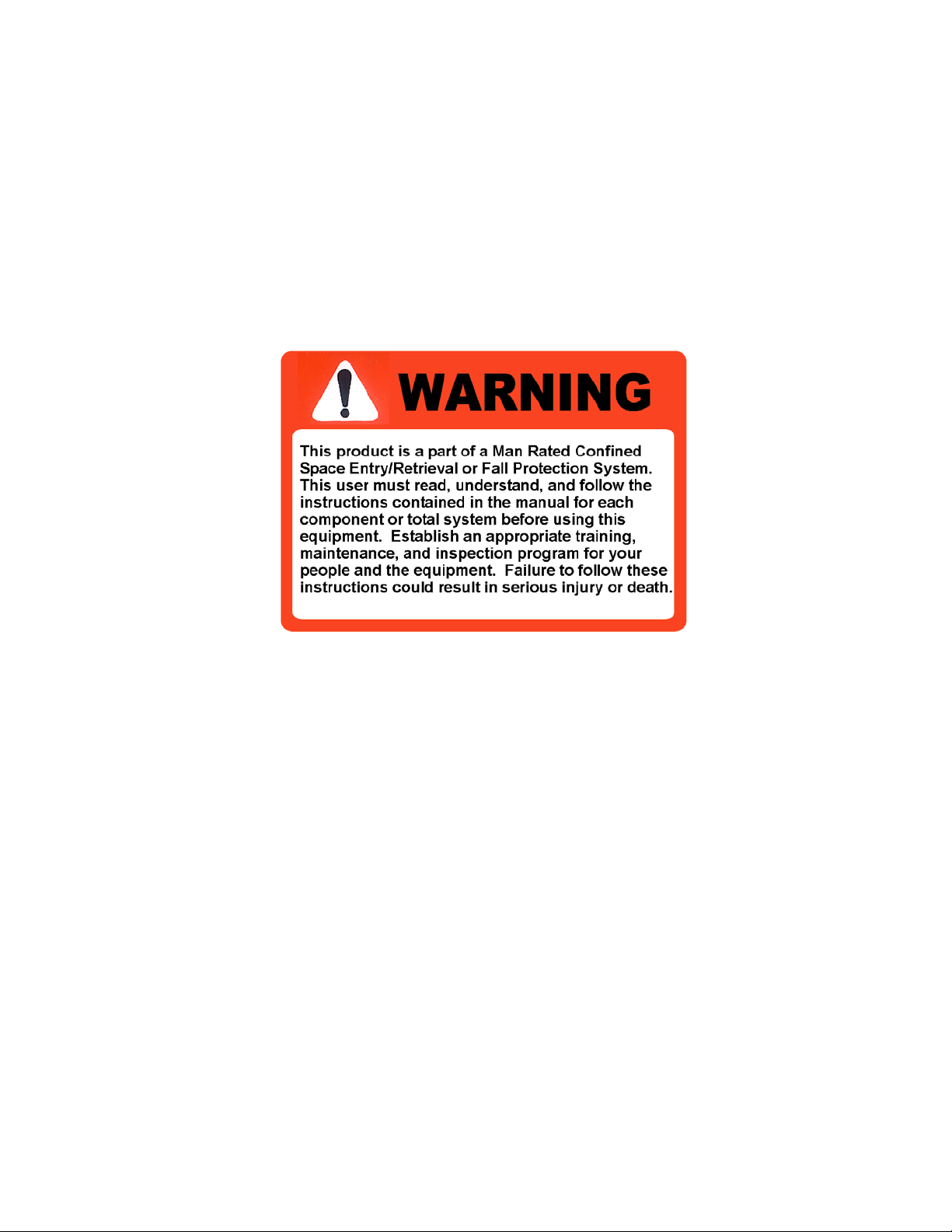
WARNING - Indicates a potentially hazardous
situation that if not avoided, could
result in death or serious injury,
and includes obvious and hidden
hazards. It may also be used to
alert against unsafe practices.
CAUTION - Indicates a potentially hazardous
situation that, if not avoided, may
result in minor or moderate injury.
It may also be used to alert
against unsafe practices.
Page 6

SAFETY
YOU are responsible of the SAFE operation,
maintenance and inspection of your Unique
Concepts Man Rated FSHRS. YOU must
ensure that you and anyone else who is going
to operate, maintain, inspect or work around the
equipment be familiar with the operating and
maintenance procedures and related SAFETY
information contained in this manual. This
manual will take you step-by-step through your
working day and alerts you to all good safety
and operating practices while using the
equipment.
Remember, YOU are the key to safety. Good
safety practices not only protect you, but also
the people around you. Make these practices a
working part of your safety program. Be certain
that EVERYONE operating this equipment is
familiar with the procedures recommended and
follows safety precautions. Remember, most
accidents can be prevented. Do not risk injury
or death by ignoring good safety practices.
• Owners must give operating instructions to
operators or employees before allowing
them to use the equipment, and at least
annually thereafter.
• The most important safety device on this
equipment is a SAFE operator. It is the
operator’s responsibility to read and
understand ALL Safety and Operating
instructions in the manual and to follow
these. All accidents can be avoided.
• A person who has not read, been trained in
using and understood all operating and
safety instructions is not qualified to operate
this equipment. An untrained operator
exposes himself and others to possible
serious injury or death.
• Do not modify the equipment in any way.
Unauthorized modification may impair the
function and/or safety and could affect the
life of the equipment.
• Think SAFETY! Work SAFELY!
2.1 GENERAL SAFETY
1. Read, understand and follow the
User Manual and all safety signs
before using, maintaining or
inspecting the equipment.
2. Refer to and follow applicable ANSI, OSHA, CE
or other Standards and local regulations.
Comply with requirements of local regulations
for your applications.
3. Establish an equipment–use training program for
experienced employees. Only trained,
competent persons shall use the equipment. An
untrained operator is not qualified to operate the
system.
4. Have a first-aid kit available for
use should the need arise and
know how to use it.
5. Provide a fire extinguisher for
use in case of an accident.
Store in a highly visible place.
6. Install and properly secure all guards
and shields before operating.
7. Wear appropriate protective gear. This
list includes but is not limited to:
- A hard hat
- Safety glasses
- Protective shoes
with slip resistant
soles
- Heavy gloves
- Protective clothing
- Face protection
8. Review and follow the Pre-Operation
Inspection before using a component in the
system or the system itself.
9. Establish a regular Maintenance and Inspection
program with your equipment and maintain
detailed records.
10. Review safety related items and operating
instructions with all personal on a regular basis.
11. Be aware of your environmental surroundings;
be sure not to use the equipment during an
electrical storm. (this equipment is conductive)
12. When using our winch, the noise level does not
exceed 70 dba.
Page 7

2.2 OPERATING SAFETY
1. Read, understand and follow the Operator’s
Manual and signs on the equipment before
using, maintaining or inspecting the
equipment.
2. Train all operators before allowing them to
use the equipment. An untrained operator
exposes themselves, bystanders and
workers to possible serious injury or death.
3. Visually inspect the equipment and all
auxiliary components and equipment before
using. Correct any problems before using
the equipment.
4. Securely anchor the winch/SRL before
using, where applicable.
5. Use only certified anchor and connector
components in your system.
6. Use only an approved full body harness for
the workers.
7. Always work in teams.
8. If applicable, do not use the winch when the
brake wear indicators display in the red or 5
years. Return winch to manufacturer for
service.
9. Do not exceed 310lbs. (141 kg) during
operation.
10. Establish a regular training program for new
and experienced workers.
11. Establish a detailed inspection program for
your equipment and document the findings.
Return the equipment to the manufacturer
for rework if any problems are found.
12. Plan your work program before starting.
Have the required people, equipment and
procedures available to do the job.
13. Establish a rescue plan before using the
equipment. Failure to achieve rapid rescue
may result in death due to suspension
trauma.
13. Do not use the equipment around physical
or environmental hazards. This list includes
but is not limited to:
a. Corrosion that may affect the structural
integrity of the life line or other components
b. Chemicals which can degrade components
and not be visible.
c. Toxic gases: Rescuers or workers can be
killed in toxic environments.
d. Heat or elevated temperatures.
e. Moving machinery: Workers or auxiliary
equipment can be contacted by or pulled
into moving components.
f. Sharp edge s: Workers or the equipment
can be injured or damaged by sharp edges
or components.
g. Electrical hazards: Stay away from power
lines or components carrying electrical
power.
h. Overload: Do not exceed 310 lbs. (141 kg)
during operation.
i. Follow confined space regulations in
Standards.
j.
Noise: wear appropriate noise protection
where necessary.
k.
Environmental hazards: do not operate
equipment during electrical storms.
2.3 MAINTAINANCE/
INSPECTION SAFETY
1. Read, understand and follow the User
Manual and signs on the equipment before
using, maintaining or inspecting the
equipment.
2. ANSI, OSHA & CE requires a regular
inspection program for all Confined Space
Entry/Retrieval Equipment and to maintain
documented results of these inspections.
Follow the inspection procedure contained
in this manual and use the inspection form
to document the results.
3. Keep instructional and safety signs clean
and legible at all times. Clean or replace as
required.
4. Lubricate equipment as per instructions in
the applicable operator’s manual.
5. Remove the equipment from service if a
problem is found during the inspection.
Return to an authorized repair depot or the
factory for service.
Page 8

3 OPERATING, NEW
OPERATOR OR OWNERS
The UCL ADVANCED FSHRS is designed to
attach to a person working at a height to
provide protection against injuries resulting from
a fall. Various accessories address a variety of
fall-arrest requirements and rescue needs.
Every new operator must read, understand and
follow the instructions in all applicable manuals.
No one should be allowed to use the equipment
without training. The training should be
reviewed with experienced operators on a
regular basis. At regular intervals perform a
detailed inspection of the equipment and
document the results. Remove from service if
deficiencies are found. Alterations or misuse of
this equipment or failure to follow instructions,
may result in serious injury of death.
It is the responsibility of the owner’s
organization or operator to read this manual
and to train all other operators before they
start working with the equipment. Follow all
safety instructions exactly. Safety is
everyone’s business. By following
recommended procedures, a safe working
environment is provided for the operator,
bystanders and the area around the work
site. Untrained operators are not qualified
to operate the equipment.
Many features incorporated into this equipment
are the result of suggestions made by
customers like you. Read this manual carefully
to learn how to operate the equipment safely
and how to set it to perform as intended. By
following the operating instructions in
conjunction with a good maintenance program,
your equipment will provide many years of
trouble-free service.
Page 9
OPERATING SAFETY
1. Read, understand and follow the User
Manual and signs on the equipment before
using, maintaining or inspecting the
equipment.
2. Train all operators before allowing them to
use the equipment. An untrained operator
exposes themselves, bystanders and
workers to possible serious injury or death.
3. Visually inspect the equipment and all
auxiliary components and equipment before
using. Correct any problems before using
the equipment.
4. Securely anchor the winch before using.
5. Use only certified anchor and connector
components in your system.
6. All anchor points, or mounting/setup
locations for permanent or portable systems
must be approved to local standards by a
qualified engineer.
7. Use only an approved body harness for the
workers.
8. Always work in teams.
9. If applicable, do not use the equipment
when the winch brake wear indicators
display in the red or 5 years in service
(which ever comes first). Return equipment
to manufacturer for service.
10. Do not exceed 310lbs. (141 kg) on the line
during operation
11. Use only retractable lifelines or shock
absorber with a maximum arrest force
(MAF) equal to or lower than the lowest
rated component of your system.
12. Establish a regular training program for
new and experienced workers.
13. Establish a detailed inspection program for
your equipment and document the findings.
Return the equipment to the manufacturer
for rework if any problems are found.
14. Plan your work program before starting.
Have the required people, equipment and
procedures available to do the job.
15.
Do not use the equipment around physical
or environmental hazards. This list includes
but is not limited to:
a. Corrosion that may affect the structural
integrity of the life line or other
components .
b. Chemicals which can degrade
components and not be visible.
c. Toxic gases: Rescuers or workers can
be killed in toxic environments.
d. Heat or elevated temperatures.
e. Moving machinery: Workers or
auxiliary equipment can be contacted
by or pulled into moving components.
f. Sharp edges: Workers or the rescue
equipment can be injured by or
damaged by sharp edges or
components.
g. Electrical hazards: Stay away from
power lines or components carrying
electrical power.
h. Overload: Do not exceed 310 lbs. (141
kg) during operation.
i. Follow regulations in Standards in your
jurisdiction.
j. Noise: wear appropriate noise
protection where necessary.
k. Environmental hazards: do not
operate equipment during electrical
storms.
Page 10

Step 2: Adjust rail height 5 to 9 feet (1.5- 3m) above the
work area by cranking the drive handle.
area/object.
Step 1: Move the unit 1 to 3 feet (0.3-1m) away from work
to the center of the work area to maximize the safe work
Step 3a: Push the unit into position so that the rail is close
area and reduce the chances of a potential fall.
2b
just contacting the surface. Lock any wheels if applicable.
Step 3b: Lower the jacks down and apply light pressure by
Step 4: If applicable, pull down the tag line to connect to
the SRL (not provided) using a full body harness to safe
access the work area. Note: The SRL line must not drag or
bend over a leading edge while accessing the work area.
5FT to 9FT
To eliminate that problem reposition the unit. Follow SRL
manufacturer instruction carefully.
(1.5m to 3 m)
WORK
SURFACE
Step 5: IMPORTANT, follow the safe working area
shown.
Step 6: If applicable, transfer tagged lifeline SRL
instruction carefully. If using an SRL more than 10 feet in
length carefully follow the safe working area guidelines as
connection to SRL on the working anchor point trolley.
Follow guidelines for the safe working area carefully, do
circumstances.
not exceed the safe working area under any
Step 7: Maximum of two operators' can be attached to the
unit, each using an individual trolley. No more than one
person can be attached to a single trolley at anytime.
2a
STEPS 1 & 2
1
Page 11

4
WORKING
SURFACE
SRL
LIFELINE
6 FT
(1.8 m)
L
C
MIN
5 FT
(1.5 m)
6 FT
(1.8 m)
POSITION
FULLY EXTENDED
STEPS 3 & 4
3a
3b
3b
Page 12

STEP 5
6 FT
(1.8 m)
VIEW
TOP
WORKING
SAFE
10 FT(3 m)(Model 20216)
20 FT (6 m)(Model 20215)
AREA
6 FT
(1.8 m)
Page 13

4 MAINTENANCE AND INSPECTION
MAINTENANCE/INSPECTION SAFETY
1. Read, understand and follow the
User Manual and signs on the
equipment before using, maintaining
or inspecting the equipment.
2. ANSI and OSHA requires a regular
inspection program for all Safety
Equipment and to maintain
documented results of these
inspections. Follow the inspection
procedure contained in this of any
other applicable the manual and use
the inspection form(s) to document
the results.
4.1 Maintenance
4.1.1 Maintenance Intervals
Daily
1. Visual Inspection
Perform a complete visual inspection. Refer
to Section 4.2.1 excluding .2. Refer to
quarter year inspection for 4.2.1.2. Remove
from service if a defect is found.
Weekly
1. Functional Inspection
Perform a functional inspection. Refer to
Section 4.2.2. Record results and keep
documentation.
2. Lubricate
Perform a unit lubrication interval. See
Section 4.1.2.
3. Keep instructional and safety labels clean
and legible at all times. Clean or replace as
required. See Section 5 for label
information and part numbers.
4. Lubricate winch as per instructions in Winch
Operator’s Manual. (if applicable)
5. Remove the equipment from service if a
problem is found during the inspection.
Return to an authorized repair depot or the
factory for service.
Annually or As Required
1. Clean FSHRS System
Thoroughly clean the FSHRS System using
mild soap on the body and labels. Be sure
the labels are legible. Refer to Section 5 for
information on ordering replacement labels
if any are damaged or become illegible.
2. Complete Inspection
Perform a complete inspection. Refer to
Section 4.2 & 4.3. Record results and keep
documentation.
3. Torque Fasteners
Critical fasteners are to be checked.
Inspection areas are indicated in
Section/Figure 4.2.1.2.
Page 14

4.1.2 Lubricants
1. Chain Lubricant
Use a light lubricant like WD-40 to lubricate
the chain.
2. Brake and Drive Lubricant
Use WD40.
Page 15

4.2 Inspection
4.2.1 Visual Inspection
A complete visual inspection should be
performed on the FSHRS System equipment
you are using prior to the operation. The
following items should be checked; and the
results recorded on the “Inspection Log” sheet
(see Section 4.3).
1. Labels
Check that all labels are clean and legible.
Clean the labels if any are dirty using a mild
soap and a damp cloth. Replace if any are
illegible (Refer to Section 5 for a listing of all
labels). See Figure 4.2.1.1.
2. Fasteners
Fasteners must be checked and tightened
to the specified torques in Figure 4.2.1.2.
Bolt Size & Grade Torque Setting
½ in., Grade 5 30-35 ft.lbs (40-48 N.m)
½ in., Grade 8 35-40 ft.lbs (48-54 N.m)
5/8in., Grade 8 35-40 ft.lbs (48-54 N.m)
Contact your local dealer or UCL manufacturer
for any replacement fasteners that may be
required.
Torque
Locations
Do not touch
Threaded Rods
Torque
Locations
Figure 4.2.1.1
Figure 4.2.1.2
Page 16

Fastners con’t
Pneumatic wheel torque locations
All bolts holding the wheel to the structure
must be a torque setting of 20 ft.lbs (27
N.m). Figure 4.1.2.2.
3. Cable Tie-Backs
Check the cable tie-backs on the structure.
The cables must be tight to apply slight
pressure on the unit, Figure 4.2.1.3. DO
NOT OVERTIGHTEN.
4. Overload Detection Gusset
This gusset is an indicator of a previous fall
or misuse/abuse. These gussets are
located on each end of the rail supporting
the rail from the vertical stanchion as shown
in Figure 4.2.1.4. Inspect the gussets
visually for straightness and there is no
visible deformation or bend indicating an
incident. Please ensure the proper M.A.F.
device is used for this product and read all
labels (see Section 5) prior to use.
This gusset not only provides visual
indication of a fall or misuse but also
provides better protection against the rest of
the rail components from becoming
damaged and reduces costly repairs to the
unit.
5. Structural Components
Check the components for cracks, dents,
bends, or breaks. Minor cosmetic damage
in the component body will not affect the
function of the FSHRS System. However if
there are major dents or any other structural
damage, the unit should be removed form
service and returned to the manufacturer for
service.
6. Corrosion
Check all components for damage from
corrosion. Although all components resist
corrosion, working in corrosive
environments can lead to damage. Inspect
all structural components and fasteners for
signs of damage. If corrosion damage is
found, remove from service and return to
the manufacturer for service.
Figure 4.1.2.2
Figure 4.2.1.3
Overload gusset assembly
Figure 4.2.1.4
Page 17

6. Brake wear Indicator
Check the brake wear indicator while
lowering the unit. If the indicator shows
into the red, remove from service and
contact the manufacturer. See Figure
4.2.1.6.
7. Synchronizing Drive Connector
If the synchronizing drive connector is
removed for any reason including
maintenance it is very important NOT to
crank the individual drives. This will
cause imbalanced height of trolley rail
which can cause serious injury or death.
See Figure 4.2.1.7.
4.2.2 Functional Inspection
A functional check should be performed on the
FSHRS prior to every use. The following
functional tests should be done; and the results
recorded on the “Inspection Log” sheet (Section
4.3).
1. System Operation and Adjustments
The FSHRS contains operational parts that
may include pulleys and /or rollers. These
parts must be carefully checked for chips,
cracks, or worn areas that can cause
malfunction during operation of the system.
Make sure that all the adjustment points are
in full functional condition. This may include
parts that contain pins, bolts, tri-screws, and
adjusting screws. There are also
mechanical adjustments which may include,
adjustable legs, sleeves, adjustable sliding
blocks, and brackets. These areas must be
kept clean from debris and corrosion for
proper functional use. If any part of the
system that includes all listed items above
becomes damaged contact your local dealer
or manufacturer for parts and/or service.
Figure 4.2.1.6
Figure 4.2.1.7
2. SRL and other Accessory Inspection
Refer to the manufacture’s operator’s
manual or instructional material for proper
functional inspection procedures for SRL’s
and accessories not covered by this
manual.
Page 18

Page 19

Date:______________
Sign Off
(if required)
Corrective Action Taken
Details
Structural Damage &
Corrosion & Details
(Secure &
Fasteners
Undamaged)
Labels
Paint &
Serial # if
Applicable
Components
4.3 Inspection Log
Sample Form. Copy page to start inspection log record book. Fill out using ball point pen.
4.3.1 Freestanding Horizontal Rail System Page______of______
Equipment Identification (Type, Application, Usage & Storage Location)
(Please write description below)
Date of Inspection:
Application of Product:
Inspector:
* Winch inspection and documentation as per Winch Manual.(if applicable)
* Record Winch serial numbers and counter reading under "components" (if applicable)
Page 20

Page 21

5 LABELS
5.1 Warning Labels
The UCL ADVANCED FSHRS uses a
label rating system that is attached to all
components on the system.
The operator and/or entrant must
establish the local standards by a
qualified engineer and only then, a
decision can be made by the rating labels
as to which is the lowest rated component
and if it meets or exceeds local
standards.
Proper maintenance of the labels must be
established by the operator/entrant to
keep system use safe. If labels are
damaged the operator/entrant must
enforce a lock-out/tag-out procedure.
New labels are available from the local
dealer or UCL manufacturer.
Page 22

6 SPECIFICATION SHEETS
6.1 General
These specification sheets contain
information necessary for the proper
installation and use of the equipment
mentioned in this manual. These
specifications contain application
specific ratings and mounting
requirements determined through
design and testing.
Please read and follow these
specification sheets carefully to ensure
the proper installation of each item.
Page 23

ISO 9001
REGISTERED
Capital Safety USA: 800.328.6146 • Canada: 800.387.7484 • Asia: + 65 6558 7758 •
Australia/New Zealand: 800 245 002 • Europe, Middle East, Africa: +33 (0) 497 10 00 10 •
Northern Europe: +44 (0) 1928 571324
www.capitalsafety.com • info@capitalsafety.com
SPECIFICATIONS
PAGE 1 OF 4
UCL Free Standing Horizontal Railing System c/w Urethane Wheels
Model#: 8520216 / 8520215
8520216
8520215
Model 8520216/8520215
Page 24

SPECIFICATIONS
PAGE 2 OF 4
UCL Free Standing Horizontal Railing System c/w Urethane Wheels
Model#: 8520216 / 8520215
ISO 9001
REGISTERED
Capital Safety USA: 800.328.6146 • Canada: 800.387.7484 • Asia: + 65 6558 7758 •
Australia/New Zealand: 800 245 002 • Europe, Middle East, Africa: +33 (0) 497 10 00 10 •
Northern Europe: +44 (0) 1928 571324
www.capitalsafety.com • info@capitalsafety.com
Page 25

SPECIFICATIONS
PAGE 3 OF 4
UCL Free Standing Horizontal Railing System c/w Urethane Wheels
Model#: 8520216 / 8520215
ISO 9001
REGISTERED
Capital Safety USA: 800.328.6146 • Canada: 800.387.7484 • Asia: + 65 6558 7758 •
Australia/New Zealand: 800 245 002 • Europe, Middle East, Africa: +33 (0) 497 10 00 10 •
Northern Europe: +44 (0) 1928 571324
www.capitalsafety.com • info@capitalsafety.com
Page 26

SPECIFICATIONS
PAGE 4 OF 4
UCL Free Standing Horizontal Railing System c/w Urethane Wheels
Model#: 8520216 / 8520215
ISO 9001
REGISTERED
Capital Safety USA: 800.328.6146 • Canada: 800.387.7484 • Asia: + 65 6558 7758 •
Australia/New Zealand: 800 245 002 • Europe, Middle East, Africa: +33 (0) 497 10 00 10 •
Northern Europe: +44 (0) 1928 571324
www.capitalsafety.com • info@capitalsafety.com
Page 27

8. SERVICE CENTERS
8.1 General
This list provides a general list of the
manufacturer(s) as well as cetified
service centres in different countries.
If you require assistance in finding the
closest service centre please call the
manufacturer(s) directly.
Manufacturer(s)
CANADA
Capital Safety - Canada
260 Export Boulevard
Mississauga, ON L5S 1Y9
Phone: 905.795.9333
Toll-Free: 800.387.7484
sales.ca@capitalsafety.com
USA
Capital Safety
3833 SALA Way
Red Wing, MN 55066-5005
Phone: 651.388.8282
Toll-Free (US): 800.328.6146
solutions@capitalsafety.com
ASIA
Capital Safety Group Asia Pte Ltd.
No. 6, Tuas Avenue 18
Singapore 638 892
Phone: 65 6558 7758
inquiry@capitalsafety.com
AUSTRALIA / NEW ZEALAND
Capital Safety Australia Ltd.
20 Fariola Street
Silverwater
Sydney NSW 2128
Australia
Toll Free: 1 800 245 002 (Australia)
Toll Free: 0800 212 505 (New Zealand)
EUROPE / MIDDLE EAST / AFRICA
Capital Safety Group E.M.E.A.
Le Broc Center– Z.I. 1ère Avenue
5600 M B.P. 15 06510
Carros Le Broc Cedex
France
Phone: + 33 4 97 10 00 10
information@capitalsafety.com
NORTHERN EUROPE
Capital Safety Group Northern Europe
Unit 7 Christleton Court
Manor Park
Runcorn
Cheshire, WA7 1ST
Phone: + 44 (0)1928 571324
csgne@csgne.co.uk
Page 28

Capital Safety USA: 800.328.6146 • Canada: 800.387.7484 •
Asia: + 65 6558 7758 • Australia/New Zealand: 800 245 002 •
Europe, Middle East, Africa: +33 (0) 497 10 00 10 •
Northern Europe: +44 (0) 1928 571324
www.capitalsafety.com • info@capitalsafety.com
Printed in Canada Revision Number: 03
Issue Date: March 21, 2007 Part Number: 8518732
 Loading...