

Page 1
© Copyright 2003 DB Industries, Inc.
User Instruction Manual
Salalift® and Salalift® II Winches
8101000 and 8102001 Series
This manual is intended to meet industry
standards, including OSHA 1910.146 and
ANSI Z117.1, and should be used as part
of an employee training program as
required by OSHA.
WARNING: This product is to be used as part of a complete system. T he
user must follow the manufacturer's instructions for each component of the
complete system. These instructions must be provided to the user of this
equipment. Manufacturer's instructions must be followed for proper use and
maintenance of this product. Alterations or misuse of this product, or failure
to follow instructions may result in serious injury or death.
IMPORTANT: If you hav e questions on the use, care, application, or
suitability for use of this safety equipment, contact DBI/SALA.
IMPORTANT: Bef ore using this equipment record the product identification
information from the ID label on the winch in the inspection and
maintenance log in section 9.0 of this manual.
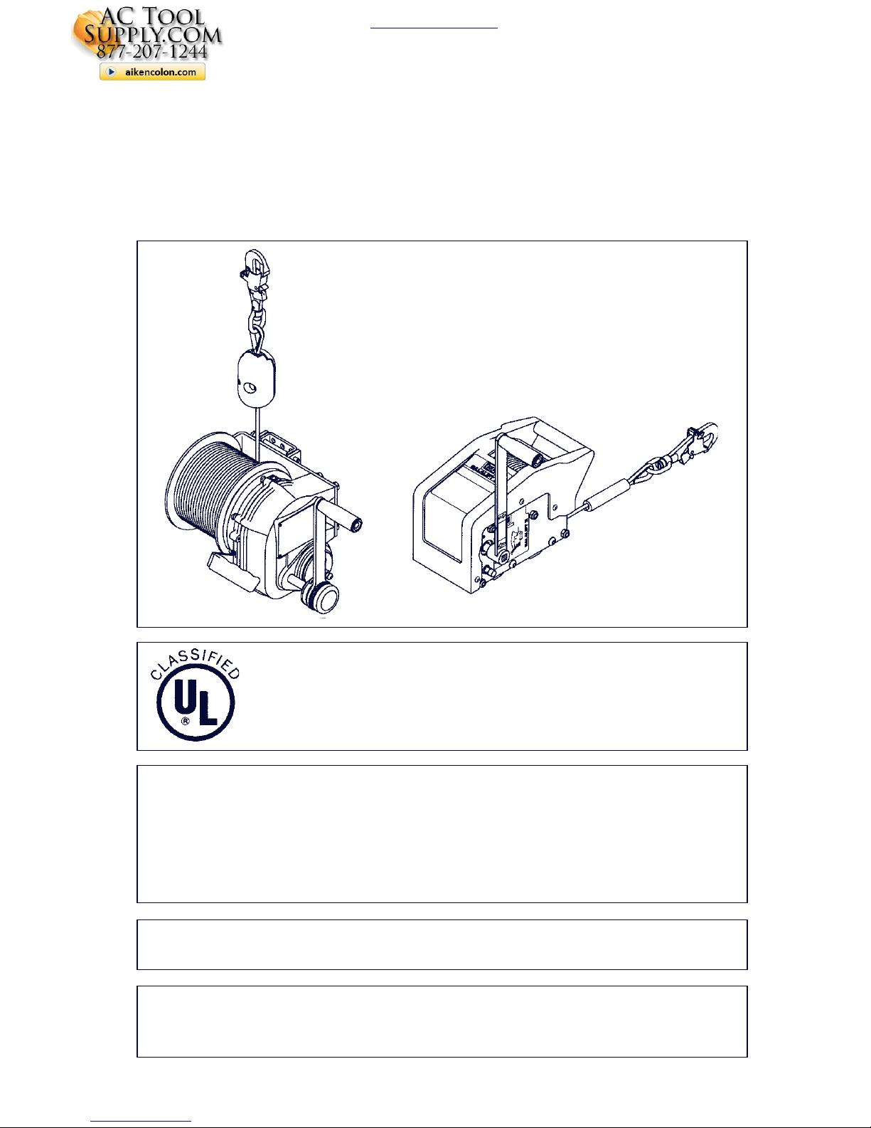
The 8101000, 8101002, 8101004, and 8101006 Salalift
Series Manually Operated Winches are classified b y Underwriters Laboratories, Inc. as to the 350 lbs. load capacity
only.
actoolsupply.com
actoolsupply.com
actoolsupply.com
Page 2

actoolsupply.com
actoolsupply.com
DBI SALA 8304000 Sealed SRL Salalift Tripod Confined Space Entry Kit
DBI SALA 8304010 Sealed SRL Salalift II Confined Space Kit
DBI SALA 8304011 Sealed SRL Salalift II Confined Space Kit
DBI SALA 8300020 Confined Space Entry Salalift II Winch Tripod 60 Ft
DBI SALA 8300030 Confined Space Entry Salalift II 60Ft Winch 7' Tripod
Page 3
3
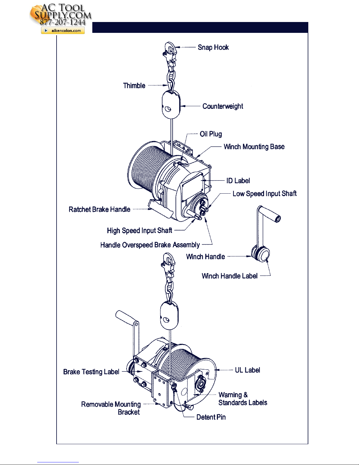
Figure 1 - 8101000 Series Parts Identification
actoolsupply.com
actoolsupply.com
Page 4
44
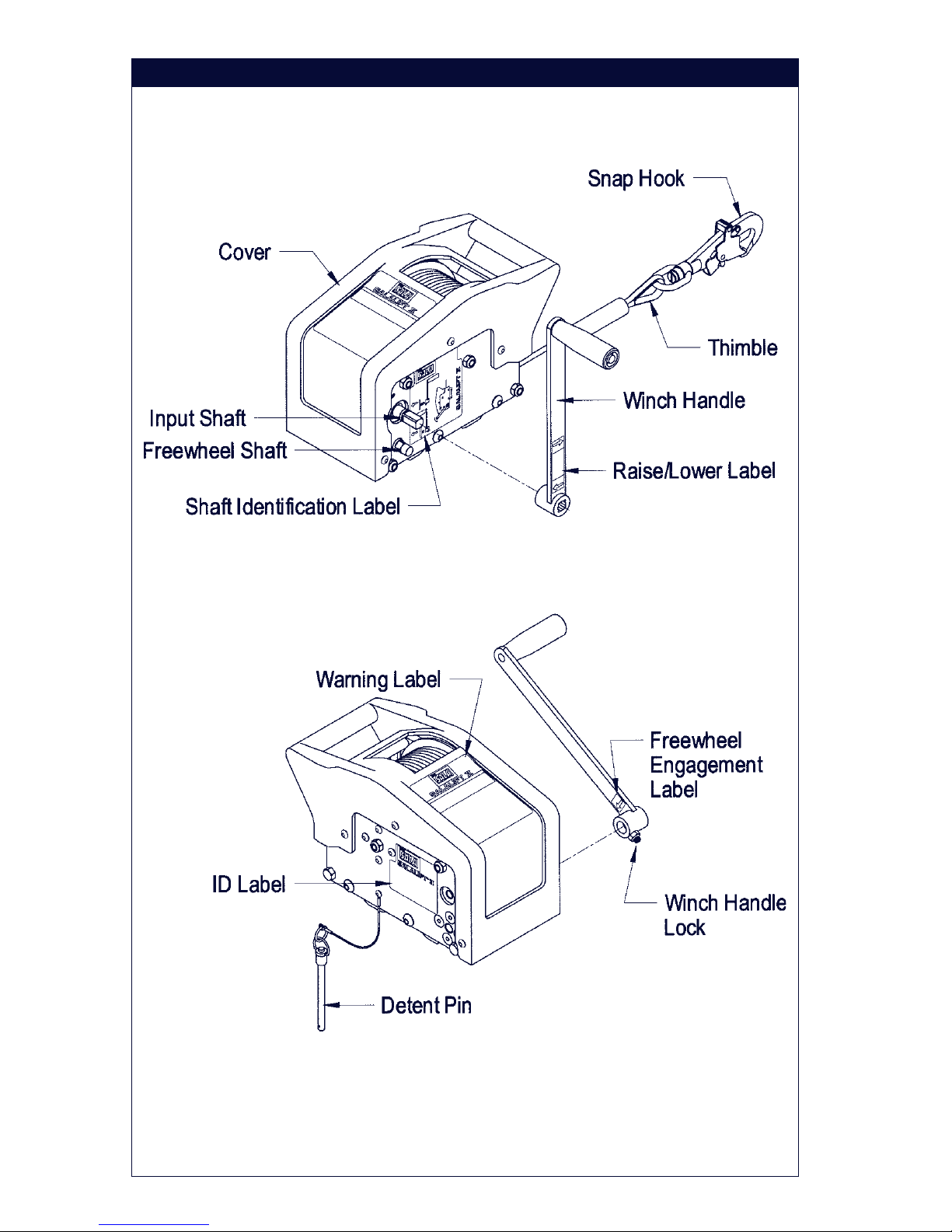
Figure 2 - 8102001 Series Parts Identification
actoolsupply.com
actoolsupply.com
Page 5

5
DESCRIPTIONS
SALALIFT® Winches:
8101000: 60 feet of 1/4 inch galvanized wire rope, carrying bag.
8101002: 60 feet of 1/4 inch stainless steel wire rope, carrying bag.
8101004: 120 feet of 1/4 inch galvanized wire rope, carrying bag.
8101006: 120 feet of 1/4 inch stainless steel wire rope, carrying bag.
8101101: 140 feet of 1/4 inch galvanized wire rope, carrying bag.
8101103: 140 feet of 1/4 inch stainless steel wire rope, carrying bag.
SALALIFT® II Winches:
8102001: 60 feet of 1/4 inch galvanized wire rope, carrying bag.
8102003: 60 feet of 1/4 inch stainless steel wire rope, carrying bag.
8102009: 90 feet of 3/16 inch galvanized wire rope, carrying bag.
8102011: 90 ft. of 3/16 inch stainless steel wire rope, carrying bag.
8102005: 120 feet of 3/16 inch galvanized wire rope, carrying bag.
8102007: 120 feet of 3/16 inch stainless steel wire rope, carrying bag.
IMPORTANT: F or special (custom) versions of this product, follo w the
instructions herein. See supplemental instructions, if included, for additional
instructions on custom equipment.
1.0 APPLICATIONS
1.1 PURPOSE: DBI/SALA Salalift winches are to be used for work
positioning (8101000 series only), personnel riding, material handling,
climbing protection, or rescue and ev acuation. These winch models are
to be used with a DBI/SALA tripod, davit arm, or other support
structure, and may be used in situations where personnel or materials
need to be raised or lowered 60-140 feet.
1.2 WINCH APPLICA TION TYPES:
A. WORK POSITIONING: The Salalift winch (8101000 series only) is
used to suspend the worker in a work position, acting as the primary
means of support. Applications include suspending a worker in a
work seat or harness. A back-up personal fall arrest system must be
attached to the suspended employee.
NOTE: OSHA requires that manual or pow ered winches be independently
evaluated and classified for use as a single point suspension system. See
OSHA regulation 29 CFR 1926.451, and 29 CFR 1910.28.
B. PERSONNEL RIDING: The Salalift or Salalift II winch is used to r aise
or lower a worker to a work level. At the work level the worker is no
longer supported by the winch. It is recommended that the w orker be
connected to a back-up arrest system while being raised or lowered.
actoolsupply.com
actoolsupply.com
Page 6

6
C. RESCUE AND EV A CUATION: The Salalift or Salalift II winch is used
to raise or lower an endangered or injured work er, or rescue
personnel. Applications include permit and non-permit confined
space entry work.
D. CLIMBING PRO TECTION: The Salalift or Salalift II winch is used to
protect a worker ascending or descending a fixed ladder or similar
structure. It is recommended that this use of the winch be restricted
to structures where other means of climbing protection; such as
permanently installed ladder safety systems or personal fall arrest
systems are infeasible. For this application, the following conditions
must be met:
1. Ladder or steps are in good condition and allows for a straight,
continuous climb .
2. The worker climbing the ladder is wearing a full body harness and
the winch line is connected to the dorsal (back) D-ring of the
harness.
3. The winch operator is trained and competent in the operation of
the winch.
4. No slack line is allowed to develop when the worker moves up or
down the ladder .
5. DBI/SALA recommends , for the 8101000 series winches only,
that an energy absorbing lanyard be connected between the
harness dorsal D-ring and the winch line.
1.3 LIMITATIONS: The following application limitations must be considered
before using this product. F ailure to observe product limitations could
result in serious injury or death.
A. INSTALLATION: The winch must be installed in accordance with the
requirements stated in section 3.0 of this manual.
B. CAPACITY: The maximum working load for this product is 350 lbs.
(160 kg).
C. PERSONAL F ALL ARREST SYSTEMS: P ersonal fall arrest
systems used with the Salalift or Salalift II winch must meet
applicable state and federal regulations and the requirements stated
in section 3.3.
D. PHYSICAL AND ENVIRONMENT AL HAZARDS: Use of this
equipment in areas with physical or environmental hazards may
actoolsupply.com
actoolsupply.com
Page 7

7
require that additional precautions be taken to reduce the possibility
of damage to this equipment or injury to the user. Hazards ma y
include, but are not limited to; high heat (welding or metal cutting),
acid or caustic chemicals, corrosive environments such as
exposure to sea water , high v oltage po wer lines , e xplosive or to xic
gases, moving machinery or sharp edges. Contact DBI/SALA if you
have questions about the application of this equipment in areas
where physical or environmental hazards are present.
E. TRAINING: This equipment is to be installed and used by persons
who have been trained in its correct application and use.
1.4 Refer to national standards, including; ANSI Z117.1, local, state, and
OSHA requirements (26 CFR 1910.146), for more information on the
application of this and associated equipment.
2.0 SYSTEM REQUIREMENTS
2.1 COMP ATIBILITY OF COMPONENTS: DBI/SALA equipment is
designed for use with DBI/SALA approved components and
subsystems only. Substitutions or replacements made with nonapproved components or subsystems may jeopardize compatibility of
equipment and may effect the safety and reliability of the complete
system.
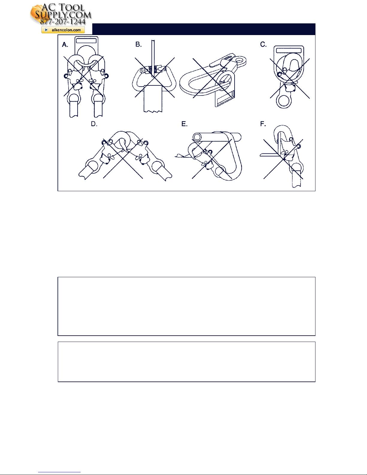
2.2 COMP A TIBILITY OF CONNECT ORS: Connectors are considered to be
compatible with connecting elements when they have been designed to
work together in such a way that their sizes and shapes do not cause
their gate mechanisms to inadvertently open regardless of how they
become oriented. Contact DBI/SALA if you have any questions about
compatibility.
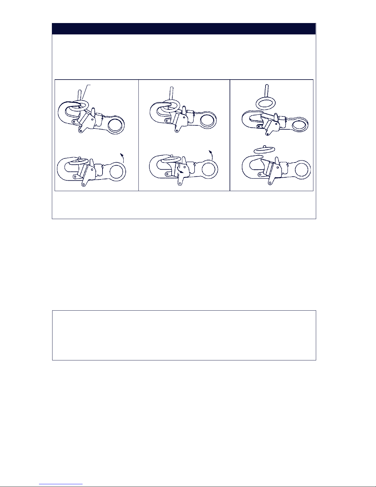
Connectors ( hooks, carabiners, and D-rings) must be capable of
supporting at least 5,000 lbs. (22kN). Connectors must be compatible
with the anchorage or other system components. Do not use equipment
that is not compatible. Non-compatible connectors may unintentionally
disengage. See Figure 3. Connectors must be compatible in size,
shape, and strength. Self locking snap hooks and carabiners are
required by ANSI Z359.1 and OSHA.
2.3 Making Connections: Only use self-locking snap hooks and carabiners
with this equipment. Only use connectors that are suitable to each
application. Ensure all connections are compatible in size, shape and
strength. Do not use equipment that is not compatible. Ensure all
connectors are fully closed and locked.
actoolsupply.com
actoolsupply.com
Page 8
8
DBI/SALA connectors (snap hooks and carabiners) are designed to be
used only as specified in each product’s user’s instructions. See Figure
4 for inappropriate connections. DBI/SALA snap hooks and carabiners
should not be connected:
A. To a D-ring to which another connector is attached.
B. In a manner that would result in a load on the gate.
NOTE: Large throat opening snap hooks should not be connected to
standard size D-rings or similar objects which will result in a load on the gate
if the hook or D-ring twists or rotates. Large throat snap hooks are designed
for use on fixed structural elements such as rebar or cross members that are
not shaped in a way that can capture the gate of the hook.
C. In a false engagement, where features that protrude from the snap
hook or carabiner catch on the anchor and without visual
confirmation seems to be fully engaged to the anchor point.
D. To each other.
E. Directly to webbing or rope lanyard or tie-back (unless the
manufacturer’ s instructions for both the lan yard and connector
specifically allows such a connection).
Figure 3 - Unintentional Disengagement (Roll-out)
If the connecting element that a snap hook (shown) or carabiner attaches to is
undersized or irregular in shape, a situation could occur where the connecting
element applies a force to the gate of the snap hook or carabiner. This force may
cause the gate (of either a self-locking or a non-locking snap hook) to open,
allowing the snap hook or carabiner to disengage from the connecting point.
1. Force is applied to
the snap hook.
2. The gate presses against
the connecting ring.
3. The gate opens
allowing the snap
hook to slip off.
Small ring or other
non-compatibly
shaped element
actoolsupply.com
actoolsupply.com
Page 9
9
F. To any object which is shaped or dimensioned such that the snap
hook or carabiner will not close and lock, or that roll-out could occur .
2.4 SUPPORT STRUCTURE STRENGTH: The support structure to which
the winch is installed must meet minimum strength requirements stated
in section 3.4
3.0 OPERATION AND USE
W ARNING: Do not alter or intentionally misuse this equipment. Consult
DBI/SALA when using this equipment in combination with components or
subsystems other than those described in this manual. Some subsystem
and component combinations may interfere with the operation of this
equipment. Use caution when using this equipment around moving
machinery , electrical hazards, chemical hazards, and sharp edges.
WARNING: Consult your doctor if there is reason to doubt your fitness to
safely absorb the shock from a fall arrest. Age and fitness seriously affect a
worker's ability to withstand falls. Pregnant women or minors must not use a
DBI/SALA winch, unless for unavoidable emergency use situations.
3.1 BEFORE EACH USE: Before each use of this equipment carefully
inspect it to ensure it is in good working condition. Check for worn or
damaged parts. Ensure all parts are present and secure. Chec k
operation of winch; ensure that it will lift, lower , and hold the load under
normal operation. Check winch and entire system for damage and
corrosion. See section 5.0 f or further inspection details. Do not use if
inspection reveals an unsafe condition.
Figure 4 - Inappropriate Connections
actoolsupply.com
actoolsupply.com
Page 10

10
3.2 PLANNING: Plan your system and how it will function bef ore starting
your work. Consider all factors that affect your safety during use. Some
important points to consider when planning your system are:
A. HAZARD EV ALU A TION: Ev aluate job site hazards prior to starting
work. Consult applicable OSHA and industry standards for
guidelines and regulatory requirements on issues such as confined
space entry , personal f all arrest systems (PFAS), and single point
adjustable suspended scaffolds.
B. WORK SITE GEOMETR Y : The installation and use of the support
structure (tripod, davit arm and base) must be consistent with the
geometric requirements stated in the associated manufacturer's
instruction manuals. When suspending working lines from the
support structure, check for obstructions or sharp edges in the work
path. Av oid working where the user may s wing and hit an object, or
where lines may cross or tangle with that of another worker .
C. SECONDAR Y OR BA CK-UP F ALL ARREST SYSTEM: When using
the Salalift winch (8101000 series) as a support for w ork positioning,
a secondary or back-up fall arrest system is required. See OSHA 29
CFR 1910.28 and 1926.451. The DBI/SALA tripod and davit arm has
provisions for connection of a secondary or back-up PFAS. See
sections 3.3 and 3.5 (A).
D. RESCUE: A means of dealing with an accident or emergency must
be planned in advance. Response time can pla y an important role in
the survival of an injured worker . Users of this equipment must be
trained in emergency procedures.
3.3 REQUIREMENTS FOR PERSONAL F ALL ARREST SYSTEMS: PFAS
used with the Salalift or Salalift II winch and support structure must
meet applicable OSHA requirements.
• The PFAS should be rigged to minimize any potential free fall and
never allow a free fall greater than 6 feet. It is recommended that the
PFAS used with this equipment include a full body harness as the
body support component. PFAS's that incorporate full body
harnesses must maintain fall arrest forces below 1,800 lbs. and arrest
the fall within 42 inches. Body belts, unless incorporated into a full
body harness, are not recommended for use with this equipment. A
typical PFAS includes a full body harness, connecting subsystem or
component (self retracting lifeline or lifeline and rope grab), and the
necessary connectors to couple the system together.
• Anchorages selected for PFAS must sustain static loads, applied in
the directions permitted by the PFAS, of at least; (A) 3,600 lbs.
actoolsupply.com
actoolsupply.com
Page 11

11
(16kN) when certification exists (see ANSI Z359.1 for certification
definition), or (B) 5,000 lbs. (22kN) in the absence of certification.
When more than one PFAS is attached to an anchorage, the
anchorage strengths set forth in (A) and (B) must be multiplied by the
number of PFAS attached to the anchorage. Per OSHA 1926.500 and
1910.66: Anchorages used for attachment of a PFAS shall be
independent of any anchorage being used to support or suspend
platforms, and must support at least 5,000 lbs. (22kN) per user
attached, or be designed, installed, and used as part of a complete
PFAS which maintains a safety factor of at least two, and is
supervised by a qualified person.
W ARNING: Read and f ollow manufacturer's instructions f or the personal fall
arrest equipment selected for use with the winch and support structure.
IMPORTANT: Body belts are not allowed f or free fall situations. Body belts
increase the risk of injury during fall arrest in comparison to a full body
harness. Limited suspension time and the potential for improperly wearing a
body belt may result in added danger to the user’ s health.
3.4 INST ALLA TION OF WINCH T O SUPPORT STRUCTURE:
A. MOUNTING BRACKET: These winches incorporate a “quick-mount”
style brack et for attachment to the support structure. DBI/SALA
tripods, davit arms, and other support structures supplied by
DBI/SALA, include a bracket that mates with the winch quick-mount
bracket. All DBI/SALA winches include the quick-mount bracket.
When using the 8102001 series winch with the 8004176 W all Mount
Bracket, a mounting adapter kit is required. Contact DBI/SALA for
more information.
B. LOAD REQ UIREMENTS: Figure 5 illustrates mounting the winch to
the support structure and the load requirements. The mounting
bracket m ust support the loads shown in Figure 5.
C. GEOMETRIC REQUIREMENTS: Refer to the support structure
manufacturer's instructions for geometric requirements. Installations
of the winch to support structures other than those provided by
DBI/SALA must meet the geometric requirements shown in
Figure 5. P osition the support structure so the load and the lifeline of
the winch can be directed over the work area when installed. For
personnel use, do not position the support structure where the
worker will hav e to swing under the support structure to reach the
work area. Avoid positioning the support structure where the working
line may abrade against sharp edges.
actoolsupply.com
actoolsupply.com
Page 12

12
IMPORTANT: P osition the winch and support structure in a location which
allows the operator to safely use the winch.
D. QUICK-MOUNT INST ALLA TION: See Figure 6. Mount the winch
using the quick-mount bracket as follows:
Step 1. Pull out the locking detent pin by depressing the button on end
of the pin. Lift the winch into place and position the slot in the
bracket o v er the fixed pin on the support structure bracket.
Step 2. Push the top of winch in toward the support structure while the
bottom rotates on the fixed pin. Align the holes and push the
detent pin through until it stops. Ensure the pin locks in place.
Figure 5 - Load/Geometric Requirements
actoolsupply.com
actoolsupply.com
Page 13

13
Step 3. Slowly pull out the winch line. Route the line o v er the support
structure pulley system. See the support structure
manufacturer's instructions for details.
E. WELDED INST ALLATIONS: If w elding the mounting bracket to a
support structure it is recommended that the welding be done by a
certified welder. P ortions of the mounting brack et that have been
exposed due to welding should be painted or otherwise protected
from corrosion.
Figure 6 - Quick-Mount Installation
3.5 OPERA TION OF WINCH:
A. CONNECTING WINCH LINE TO LOAD: See Figure 7. For
applications that do not require a secondary PFAS , the winch line
should be connected to the worker's harness back D-ring. For
applications requiring a secondary PFAS, the winch line should be
connected to a Y-type lanyard and this lany ard should be attached to
the worker's harness shoulder D-rings. The secondary lifeline should
be connected to the worker's harness back D-ring. For material
handling applications, connect the winch line to the load using a tieoff adapter or other anchoring device.
B. SALALIFT WINCH (8101000 Series): Attach the winch to the
support structure as described in section 3.4 (D). Install the winch
crank handle onto the high or low speed shaft by aligning the handle
with the shaft and pushing firmly inward until the handle snaps in
place. To release the handle from the shaft, depress the handle
release and pull the handle off the shaft. Pull the ratchet lever
downward and feed the line off the drum by rotating the crank handle
in the “lower” direction. Route the line ov er the support structure
pulley system.
actoolsupply.com
actoolsupply.com
Page 14

14
TO RAISE A LO AD: Rotate the winch crank handle clockwise when
using the low speed shaft and counterclockwise when using the high
speed shaft. For work er safety, the crank handle incorporates an
overload clutch which limits the winch lifting force on the high speed
shaft to approximately 250 lbs. and 500 lbs. on the low speed shaft,
thus reducing the possibility of injury should a worker become
entangled during retrieval. Do not exceed the rated capacity of 350
lbs.
TO LO WER A LO AD: Rotate the winch crank handle in the “raise”
direction until the ratchet brake lever can be pulled down, then rotate
the crank handle in the “lo wer” direction. When a load is suspended
from the winch, use caution when the ratchet brake lever is pulled
down since the load will be transf erred to the winch crank handle. To
prevent loss of control of the load, do not bloc k or r e strict the ratchet
lever from engaging the teeth on the drum, except by normal manual
operation. If the operator fatigues, or for any reason desires to “hold”
the load, allow the ratchet brake to engage and support the load.
The Salalift® I winch is designed and typically used for manual
operation. Certain situations where the speed of the rescue, coupled
with fatigue experienced by operator during long lifts, may
necessitate the need for a powered drive operation. Contact DBI/
SALA for more information.
C. SALALIFT II WINCH (8102001 Series): Attach the winch to the
support structure as described in section 3.4 (D). Install winch crank
handle onto the input shaft by aligning the hub of the crank handle
with the square drive marked "winch shaft" and pushing firmly
inward until handle snaps in place (the grip on the handle should
Figure 7 - Connection
actoolsupply.com
actoolsupply.com
Page 15

15
face outward). To release the crank handle from the shaft, pull the
handle off the shaft. Feed the line off the winch drum by rotating the
crank handle in the lowering direction (counterclockwise). Apply
slight tension to the line while feeding it off the drum. F ree-wheel
mode may also be used, see section 3.5 (C). Route the line over the
support structure pulley system.
TO RAISE A LO AD: Rotate the winch crank handle in the raise
direction (clockwise). To hold or momentarily suspend the load, stop
cranking. The automatic clutch/brak e will hold the load if handle is
released. The winch incorporates an overload clutch limiting the
lifting force to approximately 700 lbs., reducing the chance of injury
if a worker becomes entangled during retrieval. Do not exceed the
rated capacity of 350 lbs.
TO LO WER A LO AD: Rotate the winch crank handle in the lower
direction (counterclockwise). When low ering line without a load,
maintain slight tension on the line to aid payout.
FREE-WHEEL MODE: Remove the crank handle from the raise/lower
input shaft. Reverse the crank handle and install it onto the square
drive marked "freewheel shaft" by aligning the handle hub with the
shaft. See Figure 8. To engage free-wheel mode, rotate the crank
handle counterclockwise until it stops and hold. The line can now be
freely pulled off of the winch drum. T o a v oid build-up of slack line on
the drum, pull the line off the drum smoothly , remo ve slack on the
drum by releasing the crank handle and pulling on the line. If the line
pays out too rapidly, an ov er speed br ak e will activate and lock,
stopping the line. If this happens, return to the winch mode and
rotate the crank handle clockwise two turns to unlock the over
speed brake. Do not engage free-wheel mode with load on the lifting
line, remove load on the line before engaging free-wheel mode.
When using the Salalift II for climbing protection applications, freewheel mode is not recommended. The oper ator must be attentive to
slack line; paying out and reeling in line as needed.
D. IMP A CT INDICA T OR AND CABLE RESERVE: The Salalift II winch
is supplied with a connecting swiveling hook that incorporates a load
indicator . This indicator functions if the winch is sev erely impact
loaded or if the lifting capacity is exceeded by a preset amount. See
section 5.0 for inspection of load indicator . The Salalift II
incorporates a reserve cable retention feature on the cable drum.
With the drum near empty (single layer of cable remaining), the
shear pin is visible. See Figure 10. The reserve cab le ensures that
the shock absorbing feature is available throughout the working
range of the winch. If the winch is shock loaded at the reserve point
actoolsupply.com
actoolsupply.com
Page 16

16
of cable pay out, the shear pin will shear , allowing the shoc k
absorber to function normally . If the shear pin has been sheared, the
unit must be returned for inspection and repair . See section 5.0 for
inspection details.
IMPORTANT: Do not use winch f or lifting or lowering of more than one
person, except for emergency situations. In this case, if using the 8101000
series, the low speed shaft must be used to pre vent handle slippage. The
maximum lifting force is approximately 500 lbs.
W ARNING: If the cr anking tension eases during lowering, the person or
material being lowered has reached a work level or obstruction. Do not
continue cranking without communicating with the person or checking the
material being lowered. Always keep the cable tension firm. Slack cable
could cause a free fall.
WARNING: A minimum of four wraps of line must remain on the drum at all
times on the 8101000 series. One complete layer of line must remain on the
8102001 series. Do not attempt to reverse wind the line onto the drum. Line
must wind onto the drum by turning the crank handle in the "raise" direction
only . Check periodically to see that the line is winding ev enly on the drum.
Use gloves when handling line.
4.0 TRAINING
4.1 It is the responsibility of the user to assure they are familiar with these
instructions, and are trained in the correct care and use of this equipment.
Figure 8 - Free-Wheel Mode
actoolsupply.com
actoolsupply.com
Page 17

17
User must also be aware of the operating characteristics, application
limits, and the consequences of improper use of this equipment.
IMPORTANT: T raining m ust be conducted without exposing the trainee to a
fall hazard. T raining should be repeated on a periodic basis.
5.0 INSPECTION
5.1 FREQUENCY :
• Before Each Use: Visually inspect per steps listed in sections 5.2
and 5.3.
• Monthly: A formal inspection of the winch should be done by a
competent person other than the user. See sections 5.2 and 5.3 for
guidelines. Record results in the inspection and maintenance log in
section 9.0.
• Annual: It is recommended that the winch be serviced by a factory
authorized service center or the manufacturer. Extreme working
conditions may require increasing the frequency of inspections.
Annual servicing shall include, but not be limited to, an intensive
inspection and cleaning of all internal and external components.
Failure to provide proper service may shorten product life and could
endanger performance.
• After An Impact: Inspect entire winch according to section 5.2.
W ARNING: If the winch has been subjected to impact forces, it must be
immediately removed from service and inspected. If the winch fails to pass
the inspection, do not use. The equipment must be sent to an authorized
service center for repair .
IMPORTANT: Extreme working conditions (harsh environment, prolonged
use, etc.) may require increasing the frequency of inspections.
5.2 GENERAL INSPECTION STEPS FOR ALL WINCH MODELS:
Step 1. Inspect all screws, bolts and nuts. Ensure they are securely
attached and tight. Check to see if any bolts, nuts or other
parts are missing, or have been substituted or altered in any
wa y. Inspect covers, housings, guards, etc. Ensure they are
free of cracks, dents, or other damage.
Step 2. Crank handle must lock positively onto the shaft and be free of
cracks, bends, or other damage.
actoolsupply.com
actoolsupply.com
Page 18

18
Step 3. Connecting hook must not be damaged, broken, distorted, or
have an y sharp edges, burrs, crac ks, worn parts, or corrosion.
Ensure the connecting hook works properly . Hook gate must
move freely and loc k upon closing. Hook must swivel freely.
Step 4. Wire Rope: Inspect entire length of wire rope assembly starting
at the hook. Always wear protective gloves when inspecting
wire rope.
A. Inspect for broken wires by passing the wire rope through gloved
hands, flexing it every few inches to expose breaks. Broken wires
can be removed b y bending the wire back and f orth parallel to the
rope length. Do not attempt to pull wires out of rope. Inspect for
kinks, cuts, crushed burned areas, or other damage. Wire rope with
serious damage must be removed from service.
B. The wire rope assembly must be replaced by an authorized service
center if there are six or more randomly distributed broken wires in
one lay, or three or more broken wires in one strand in one la y. Note:
A “lay” of wire rope is the length of wire rope that it takes for a
strand (the larger groups of wires) to complete one revolution or
twist along the rope.
C. The wire rope assembly must be replaced by an authorized service
center if there are any broken wires within one inch of the metal
compression sleev es at either end of the assembly. Note: To inspect
wire rope area near compression sleeves on hook end, remove
counterweight (8101000 series) or slide rubber hook bumper up on
wire rope (8102001 series).
D. Inspect entire length of wire rope for signs of corrosion. Severely
corroded wire rope must be replaced.
Synthetic Rope: Inspect for the following if the winch uses synthetic rope:
A. Inspect for concentrated wear, frayed strands , brok en yarns, cuts,
and abrasions. The line must be free of knots, e xcessiv e soiling,
heavy paint buildup, and rust staining throughout its length.
B. The line must be free of chemical or heat damage, indicated by
brown, discolored, or brittle areas.
C. The line must be free of ultraviolet damage, indicated by discoloration
and the presence of splinters and slivers on the rope surface.
D. All of the above factors are known to reduce rope strength. As a rule
of thumb, rope strength is reduced proportional to the cross
actoolsupply.com
actoolsupply.com
Page 19

19
sectional area of the rope damaged. Damaged or questionable rope
should be replaced by an authorized service center.
Step 5. Inspect all identification and warning labels, ensuring that they
are legible and securely attached. See Figure 1 (8101000
series), Figure 2 (8102001 series) and section 8.0.
Step 6. Inspect each system component (support structure, back-up
fall arrest system, body support, connectors, etc.) according to
manufacturer's instructions.
Step 7. See additional inspection steps for the winch in sections 5.3,
5.4, and 5.5.
5.3 INSPECTION OF SALALIFT WINCH (8101000 SERIES): The f ollowing
steps are additional inspection procedures to those in section 5.2 that
must be performed on the 8101000 series winch. See Figure 1.
Step 1. Check operation of the winch in high and low speed positions; it
must crank up and down freely. Stiff or rough operation ma y
indicate a worn gear or bearing.
Step 2. Inspect the ratchet brake . With the brak e engaged, the drum
should be prev ented from paying off cab le. The spring must be
in place and undamaged. The ratchet brak e lev er must fully
engage the teeth on the drum, the drum teeth must be in good
condition.
Step 3. Inspect for oil in the gearbox by removing plug on top and tilting
unit so oil can be seen through hole. Inspect for oil leaks.
Step 4. Check operation of the handle over speed brake as follows:
A. Over le v el ground set up support structure and winch as it will be
used.
B. By raising or lowering the winch cable, position the lifting hook to
approximately chest height.
C. Remove the winch crank handle and have someone hold the ratchet
brake lever in its disengaged position, such as when lowering a
load.
D. Pull down sharply on the lifting hook to engage the over speed
brake.
actoolsupply.com
actoolsupply.com
Page 20

20
E. If the brake fails to engage or noticeable brake slippage occurs,
remove from service and return to an authorized service center for
repair.
Step 5. Check operation of the drum over speed brake as follows, see
Figure 9:
A. To test the drum over speed br ake, remov e the handle ov er speed
brake assembly. Using a snap ring pliers, remo ve the ring that
retains the handle over speed brake assembly on the low speed
shaft. Remov e the brak e assemb ly, taking care not to damage the
pawl springs on the back side of the brake. Note: If damage exists
on the shaft such as a nick or corrosion, repair the damaged area
using a file or emery cloth before removing the brake assemb ly.
B. With the handle over speed brake removed, on level ground, set up
the support structure and winch as it will be used. To test the drum
over speed brake, remove the crank handle and disengage the ratchet
brake, then pull down sharply on the winch cable to engage brake.
C. If the brake fails to engage or slippage of more than one inch occurs
(a small amount of brake slippage is normal), remove the winch
Figure 9 - Inspecting level wind 8101000
actoolsupply.com
actoolsupply.com
Page 21

21
from service immediately and return to an authorized service center
for repair .
D. If the brake functions properly, reassemble the handle ov er speed
brake. Ensure the pawls are in place and the “A” side is showing on
each pawl. Reinstall the retaining ring onto the shaft. Test the handle
over speed brake for proper operation using the method given in
step 4.
Step 6. See Figure 9. Inspect the level wind assuring that it moves
freely and applies pressure against the line. If the plastic wear
pad needs to be replaced, return the winch to an authorized
service center.
5.4 INSPECTION OF SALALIFT II WINCH (8102001 SERIES): The
following steps are additional inspection procedures to those in section
5.2 that must be performed on the 8102001 series winch. See Figure 2.
Step 1. Check operation of the free-wheel mode and the drum over
speed brake as follows:
A. Engage free-wheel mode by connecting the crank handle to the
free-wheel shaft and rotating the handle counterclockwise. The
winch line should pay out freely. Pull down sharply on the winch line
with the winch in the free-wheel mode to engage the brake.
B. The brake must lock and hold. If the brake fails to engage or
slippage of more than one inch occurs (a small amount of brake
slippage is normal), remove the winch from service immediately and
return to an authorized service center for repair .
Step 2. See Figure 10.
Inspect the shear
pin. The shear pin
should retain one
complete wrap of
line on the drum. If
the shear pin is
broken or missing
the unit must be
returned to an
authorized service
center for repair .
Figure 10 - Inspecting shear pin
actoolsupply.com
actoolsupply.com
Page 22

22
Step 3. See Figure 11. Inspect the impact indicator on the snap hook. If
the hook is in the indicated mode, return the winch to an
authorized service center for repair .
Step 4. See Figure 12. Inspect the level wind assuring that it moves
freely and applies pressure against the line. If the plastic wear
pad needs to be replaced return the winch to an authorized
service center.
5.5 If inspection or operation reveals a defective condition, remove the
winch from service immediately and contact an authorized service
center for repair .
NOTE:
Only DBI/SALA or parties authorized in writing may mak e repairs to
this equipment.
6.0 MAINTENANCE, SERVICING, STORAGE
6.1 P eriodically clean the exterior of the winch using water and a mild
detergent solution. Clean labels as required. At least twice a year , clean
and lubricate the wire rope. Do not use solvents to clean the wire rope
as they will remove internal lubrication. Lubricate wire rope using a cloth
(wearing gloves) and a light machine oil.
6.2 LUBRICA TION OF SALALIFT WINCH;
• For the 8101000 series Salalift winch, the gear box contains eight
ounces of high quality gear oil, SAE 80 or 90. The oil does not require
changing unless there is evidence of contaminants in the oil. See
section 5.3, step 3. If the oil is contaminated or leaking contact DBI/
SALA for repair.
Figure 12 - Inspection level wind 8102000
Figure 11 - Impact Indicator
actoolsupply.com
actoolsupply.com
Page 23

23
daoLgnikroWdetaR.sbl053
epyTepoReriW
,leetssselniatsrodezinavlag73x6,retemaidhcni4/1
leetssselniatsrodezinavlag91x7,retemaidhcni61/3
epyTepoRcitehtnyS retseylopdiarbnodiarbeporcitehtnysretemaidhcni8/3
yticapaCmurD
teef041:elbachcni4/1:seireS0001018
teef58:elbachcni4/1:seireS1002018
teef051:elbachcni61/3
thgieW
.sbl26:0001018
.sbl17:4001018
.sbl63:1002018
.sbl53:9002018
.sbl73:5002018
raeG/deepSgnirewoLrognitfiL*
oitaR
oitar1:6.6/egareva.nim/tf2.31:deepSwoLseireS0001018
oitar1:3.3/egareva.nim/tf8.62:deepShgiHseireS0001018
oitar1:6/egareva.nim/tf5.21:seireS1002018
lairetaM
,leetsdetalpcnizdna,munimulayltnanimoderP
)ylnoseireS1002018(enelyhteyloP
• For the 8102001 series Salalift winch, lubrication should be applied
periodically to the winch drum gear. Maintain a light film of grease on
the drum gear teeth at all times. Apply grease to the drum gear teeth
as required. Do not over lubricate.
6.3 Replacement parts, as well as additional maintenance and servicing
procedures, must be completed b y a factory authorized service center.
An authorization and a return number must be issued by DBI/SALA.
6.4 Store this equipment in a cool, dry , clean environment out of direct
sunlight. A v oid areas where chemical v apors e xist. Inspect after any
period of extended storage.
6.5 Clean and store body support, support structure, and associated
system components according to separate instructions provided with
that equipment.
7.0 SPECIFICATIONS
* Note: Speeds given assume 60 rpm cranking rate. Actual rates may
vary depending on cranking speed and the amount of rope on the
drum.
• The 8101000, 8101002, 8101004, and 8101006 manually operated
winches are classified by Underwriters Laboratories, Inc. as to the
350 lbs. load capacity only.
actoolsupply.com
actoolsupply.com
Page 24

24
8101000 Series ID Label
8101000 Series UL Label
8101000 Series Brake T esting Label
8.0 LABELING
8.1 The following labels must be present and fully legible:
actoolsupply.com
actoolsupply.com
Page 25

25
8101000 Series W arning Label
8101000 Series Standards Label
8101000 Series Winch Handle Label
8102001 Series W arning Label
8.1 Labeling, continued:
actoolsupply.com
actoolsupply.com
Page 26

26
8102001 Series
Raise/Lower Label
8102001 Series
Free wheel
Engagement Label
8102001 Series Shaft Identification Label
8102001 Series ID Label
8.1 Labeling, continued:
actoolsupply.com
actoolsupply.com
Page 27

27
9.0 INSPECTION AND MAINTENANCE LOG
SERIAL NUMBER: ____________________________________________
MODEL NUMBER: ____________________________________________
DATE PURCHASED: __________________________________________
ETADNOITCEPSNISMETINOITCEPSNI
DETON
NOITCAEVITCERROCECNANETNIAM
DEMROFREP
:yBdevorppA
:yBdevorppA
:yBdevorppA
:yBdevorppA
:yBdevorppA
:yBdevorppA
:yBdevorppA
:yBdevorppA
:yBdevorppA
:yBdevorppA
:yBdevorppA
:yBdevorppA
actoolsupply.com
actoolsupply.com
Page 28

28
9.0 INSPECTION AND MAINTENANCE LOG
SERIAL NUMBER: ____________________________________________
MODEL NUMBER: ____________________________________________
DATE PURCHASED: __________________________________________
ETADNOITCEPSNISMETINOITCEPSNI
DETON
NOITCAEVITCERROCECNANETNIAM
DEMROFREP
:yBdevorppA
:yBdevorppA
:yBdevorppA
:yBdevorppA
:yBdevorppA
:yBdevorppA
:yBdevorppA
:yBdevorppA
:yBdevorppA
:yBdevorppA
:yBdevorppA
:yBdevorppA
actoolsupply.com
actoolsupply.com
Page 29

29
9.0 INSPECTION AND MAINTENANCE LOG
SERIAL NUMBER: ____________________________________________
MODEL NUMBER: ____________________________________________
DATE PURCHASED: __________________________________________
ETADNOITCEPSNISMETINOITCEPSNI
DETON
NOITCAEVITCERROCECNANETNIAM
DEMROFREP
:yBdevorppA
:yBdevorppA
:yBdevorppA
:yBdevorppA
:yBdevorppA
:yBdevorppA
:yBdevorppA
:yBdevorppA
:yBdevorppA
:yBdevorppA
:yBdevorppA
:yBdevorppA
actoolsupply.com
actoolsupply.com
Page 30

9.0 INSPECTION AND MAINTENANCE LOG
SERIAL NUMBER: ____________________________________________
MODEL NUMBER: ____________________________________________
DATE PURCHASED: __________________________________________
ETADNOITCEPSNISMETINOITCEPSNI
DETON
NOITCAEVITCERROCECNANETNIAM
DEMROFREP
:yBdevorppA
:yBdevorppA
:yBdevorppA
:yBdevorppA
:yBdevorppA
:yBdevorppA
:yBdevorppA
:yBdevorppA
:yBdevorppA
:yBdevorppA
:yBdevorppA
:yBdevorppA
30
actoolsupply.com
actoolsupply.com
Page 31

Equipment offered by DBI/SALA is warranted against factory defects in
workmanship and materials for a period of two years from date of installation
or use by the owner , pro vided that this period shall not exceed two y ears
from date of shipment. Upon notice in writing, DBI/SALA will promptly
repair or replace all defective items. DBI/SALA reserves the right to elect
to have any defective item returned to its plant for inspection before making
a repair or replacement. This warranty does not co ver equipment damages
resulting from abuse, damage in transit, or other damage beyond the control
of DBI/SALA. This w arranty applies only to the original purchaser and is
the only one applicable to our products, and is in lieu of all other warranties,
expressed or implied.
WARRANTY
actoolsupply.com
actoolsupply.com
 Loading...