

DB Elettronica Telecomunicazioni CTX 5, CTX 10, CTX 20 User Manual

DB ELETTRONICA TELECOMUNICAZIONI S.p.A.
Pag. 1/86
CTX 5/10/20
5W/10W/20W
Analog TV Exciter
UHF Band
User’s Manual Release 1.2
DB ELETTRONICA TELECOMUNICAZIONI SpA
Riviera Maestri del Lavoro 20/1 – 35127 Padova
Ph. +39 049 8700588 – E-mail: sales@dbbroadcast.com

DB ELETTRONICA TELECOMUNICAZIONI S.p.A.
Pag. 2/86
INDEX
1
INTRODUCTION.................................................................................................................................................... 3
2 TECHNICAL SPECIFICATIONS......................................................................................................................... 7
2.1 TECHNICAL FEATURES ....................................................................................................................................... 7
3 UNPACKING ........................................................................................................................................................... 9
4 INSTALLATION AND SWITCHING ON PROCEDURE ................................................................................. 9
5 MENU MAP ........................................................................................................................................................... 11
6 FRONT PANEL MENU ........................................................................................................................................ 15
6.2 CONFIGURATIONS MENU .................................................................................................................................. 15
6.3 STATUS MENU .................................................................................................................................................. 19
6.4 SYSTEM MENU ................................................................................................................................................. 20
7 FREQUENCY CHANGE ...................................................................................................................................... 21
8 AUDIO AND VIDEO MODULATOR BOARD ................................................................................................. 24
9 PRECORRECTION AND UP CONVERTER BOARD .................................................................................... 42
9.2 FRONT PANEL TRIMMERS ................................................................................................................................. 43
10 OSCILLATOR AND MIXER ............................................................................................................................... 60
11 5 WPS FINAL AMPLIFIER MODULE (DRIVER) ........................................................................................... 63
12 DISPLAY MODULE ............................................................................................................................................. 72
13 WEB MODULE ..................................................................................................................................................... 76
14 10 MHZ REFERENCE OSCILLATOR .............................................................................................................. 78
15 SWITCHING POWER SUPPLY BOARD (MODEL RS 150-24) ..................................................................... 80
16 AUXILIARY SWITCHING POWER SUPPLY BOARD NR 1 (MODEL 001-0 00070-00) ............................ 82
17 AUXILIARY SWITCHING POWER SUPPLY BOARD NR 2 (MODEL 0104-010) ..................................... 85

DB ELETTRONICA TELECOMUNICAZIONI S.p.A.
Pag. 3/86
1 INTRODUCTION
This new technology exciter has the function to modulate the video and audio signals referring to
the analog standard (PAL, NTSC or SECAM) and to convert the IF signal generated internally into
the RF signal at the transmission frequency.
The input video and audio signals are first of all modulated to generate the IF signal that is pre-
corrected by a 12 slopes precorrection board and converted into the RF signal.
The changing of the transmitted frequency is easily possible from the front panel working on the
unit directly by software commands that modify the PLL local oscillator settings. It is possible to
set whatever frequency inside the IV-V band only setting the desired channel using the front panel
buttons, with a precision of 1 Hz thanks to the high precision oscillator present on the up-converter
module.
It is also possible to have any locking to a 5MHz or 10 MHz external standard oscillator, in order to
obtain a high necessary stability ratio (precision offset). The standard setting is for a 10 MHz
external reference but it is possible to change the setting for accepting a 5MHz input as indicated in
the following paragraphs.
All the main parameters of the unit, including the data related to the audio and video input signals,
their processing and the output can be monitored in the front panel and also via WEB with a remote
control through web browser: an internal board allows the unit to be connected to a LAN using a RJ
45 interface in order to have access to all the functioning parameters of the unit and to send
commands working on a web page in a common web browser (Internet Explorer 6+) without the
installation of any special software.
DB ELETTRONICA TELECOMUNICAZIONI S.p.A.
Pag. 4/86
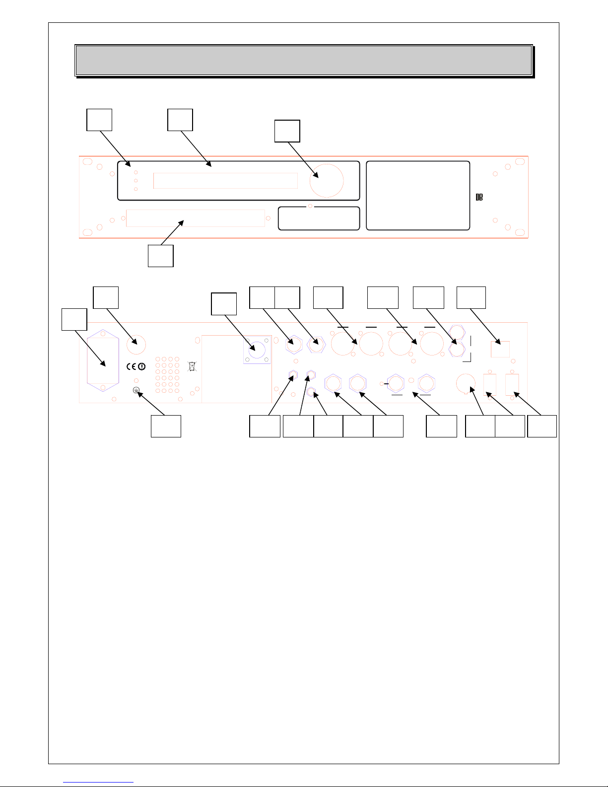
Front View
CTX - TV EXCITER
WARNING
ALARM
ON
MADE IN ITALY
BROADCAST
Rear View
FUSE 3.1 5T
115-230 Vac
ENABLE
ADJ
50/60 Hz
RF MON.
RF OUT
IF IN
IF OUT
EXT FWD
RF REM
RF IN
RF OUT
INPUT OUTPUT
INPUT OUTPUT
OUT
IN
VIDEO
LAN
RS485
CTRL OUT
FWD
DC OUT
REDUCTION
AUDIO 2 AUDIO 1
INPUT OUTPUT
10MHz
1. Front panel leds (ON, WARNING, ALARM)
2. LCD display
3. Front panel buttons (up, down, left, right, OK)
4. External access to the trimmers for the parameters adjustment
5. Mains plug
6. Fuse
7. RF Output N connector (5 W output from the RF amplifier stage)
8. IF Input (for an external IF signal)
9. IF Output (to give the IF internally generated to another equipment)
10. Audio 2 input/output connectors
11. Audio 1 input/output connectors
12. Video input/output connectors
13. LAN port (RJ 45 interface)
14. RS 485 port
15. CNTRL OUT port (it gives NC, NO and common contacts)
16. Enable connector (to enable the unit to function – to be connected to the control logic unit in case it is present
on the equipment)
17. 10 MHz external reference connectors (input and output)
18. RF OUT connector – output of the modulation board with 0 dBm level
19. RF IN connector – input of the RF amplifier stage @ 0 dBm in case of external modulation
20. RF REM REDUCTION connector – for the derating function in case of control logic unit present on the
equipment
21. EXT FWD connector – monitor FWD signal in case of external AGC
22. FWD DC OUT connector – DC voltage proportional to the RF output power of the CTX exciter
1 2
3
5
6
7
8 9 10 11 12 13
14 15 16 17 18 19 20 21 22 23
4
DB ELETTRONICA TELECOMUNICAZIONI S.p.A.
Pag. 5/86
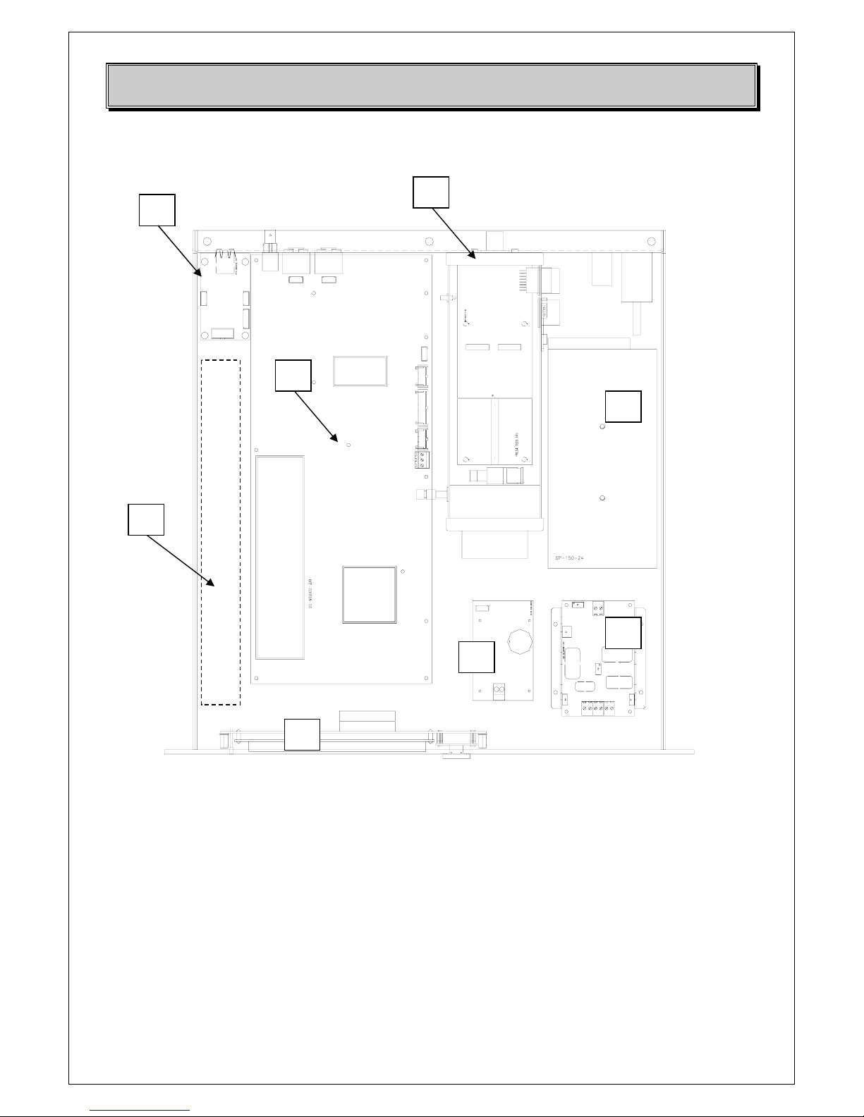
Internal top view
1. Web interface board (001-000092-00)
2. Audio/Video Modulator (0001-000109-00)
3. 2
nd
audio option
4. Final amplifier part
5. Switching Power supplies (RS 150-24)
6. Display board (001-000113-00)
7. Switching power supply board nr 1 (001-000070-00) for the generation of the +/- 15V, +5V
8. Switching power supply board nr 2 (0104-010) for the generation of +15V
1
2
3
4
5
7
6
8
DB ELETTRONICA TELECOMUNICAZIONI S.p.A.
Pag. 6/86
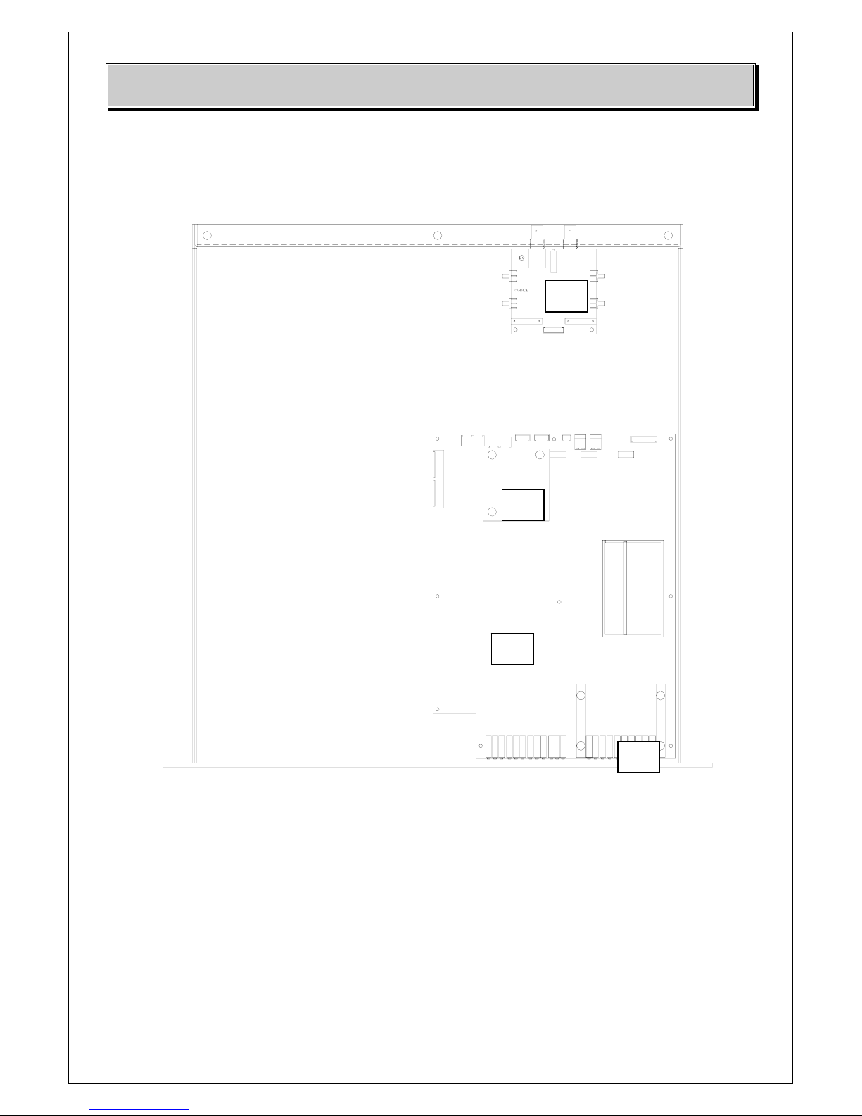
Internal bottom view
9. Pre-correction and Up converter boards (001-000114-00)
10. External reference oscillator 5/10 MHz (001-000112-00)
11. Oscillator and Mixer (001-000081-00)
12. Band Pass filter
12
11
9
10

DB ELETTRONICA TELECOMUNICAZIONI S.p.A.
Pag. 7/86
2 TECHNICAL SPECIFICATIONS
2.1 Technical Features
• All analog TV standards available
• Very compact size, modular design: increases reliability and simplifies maintenance
operation.
• Common amplification sound and vision carriers.
• High performance linearity corrector.
• Very high MTBF.
• Full band coverage without adjustment.
• Synthesized local oscillator facility.
• Mono/Stereo/Dual sound version available.
Environmental data
Environment temperature operating range 0°C to +50 °C.
Maximum allowable relative humidity
95%
Power supply
165 ÷ 280 VAC, single phase
50/60 Hz ±2%
Power factor > 0.9
Input/output Connectors
Audio input (1) XLR-31, 600Ω
Video input (1) BNC, 75 Ω
Modulated RF output N, 50 Ω
Dimensions and weight
Standard 19” 2U – 482x500x90H mm –10kg
Operating frequency range UHF – Band IV & V (470-860MHz)
TV Standards B, G, D, K, M, N, I
Output power 5Wps (CTX 5/U), 10Wps (CTX 10/U), 20Wps (CTX 20/U)
1) Video Input 75 ohm – BNC
Input return loss > 35dB (0,25 ÷ 6MHz)
Video input level 1Vpp ± 6dB adjustable
DC restoration circuit at black porch

DB ELETTRONICA TELECOMUNICAZIONI S.p.A.
Pag. 8/86
2) Video modulation parameters
Amplitude / frequency response ± 0,5dB (within the video band)
Differential gain at nominal power < 4%
Differential phase at nominal power < ± 2°
2TK factor < 1,5%
Group delay PV 0.75/5 MHz < ± 30nS (within the video band)
Sync pulse compression at nominal power < 3%
In-band intermodulation
(ref. to nominal power with 3 tones method Vc –5dB; Sc –10dB; Cc –17dB) < -60dB
Off-band spurious radiation < -60dB
S/N ratio (weighted) > 60dB
External reference frequency input 5 or 10MHz
Local oscillator stability (0 – 50 °C) < 2.5 ppm/year
(with optional high stability) < 0.5 ppm/year
L.O. frequency resolution 50kHz steps (standard version)
1Hz steps (with DDS precision offset option)
1) Audio Input XLR, two double inputs (stereo, A1, A2)
Input impedance 600 Ohm or 10 kOhm (balanced or unbalanced)
Input level 6dBm ± 6dB for ± 50kHz frequency deviation
2) Audio modulation characteristics
Modulation FM (F3) with maximum deviation ±50kHz
Pre-emphasis 50μs or 75μs
Amplitude / frequency response 30Hz ± 15kHz ± 0,5dB
Harmonic distortion < 0,1% (30Hz ÷ 15kHz by ± 50kHz deviation)
Intermodulation d2< 0,3%, d3 < 0,5% between 15kHz and
100kHz at ± 50kHz total deviation
S/N ratio > 65 dB
Separation between channels > 75 dB
Common mode rejection ratio of audio inputs (balanced mode) > 56 dB

DB ELETTRONICA TELECOMUNICAZIONI S.p.A.
Pag. 9/86
3 Unpacking
The equipment becomes the property of the customer when the equipment is delivered to the
carrier. Carefully unpack the transmitter. Perform a visual inspection to determine that no apparent
damage has been incurred during shipment. All shipping materials should be retained until it is
determined that the unit has not been damaged. Claims for damaged equipment must be promptly
filed with the carrier or the carrier may not accept the claim.
The contents of the shipment should be as indicated on the packing list. If the contents are
incomplete, or if the unit is damaged electrically or mechanically, notify both the carrier and DB
Elettronica.
4 Installation and switching on procedure
CAUTION: Before turn the equipment on, ensure that all RF Loads, RF cables and connectors are
properly connected. To prevent damage to the amplifiers, it is essential that either the feeder and
antenna system or the dummy load have a good in band return loss.
Failure to observe the above caution and also the installation instructions of this amplifier may
cause damages to the amplifiers for which DB Elettronica cannot be considered responsible.
n PREVENTION OF ACCIDENTS
When it is used in normal applications and within the parameters defined in the technical
specifications, this equipment does not endanger health and safety, provided that normal operating
and engineering safety practices are observed and that it is used only by authorized, trained and
qualified personnel.
o THERMIC AND ENVIRONMENTAL CONDITIONS
- A too high environmental temperature (in any case not higher than 45°C) shall cause a non-
adequate rack cooling putting the equipment in hard working conditions.
- An air conditioner should be installed to keep the room temperature constant even in case of
external temperature variation.

DB ELETTRONICA TELECOMUNICAZIONI S.p.A.
Pag. 10/86
pSWITCHING ON PROCEDURE
• Connect an audio generator to the audio inputs of the unit with a 0 dBm signal of test;
• Connect a video generator on the video input of the unit with a black signal (0% field) as test
signal;
• Connect a dummy load of at least 50 W on the RF output of the unit in case the CTX is used
as stand alone, or connect a dummy load properly dimensioned at the total output of the
transmitter in case the CTX is a driver unit;
• Connect the CTX to the mains (220 VAC ± 10%, 50/60 Hz) and switch on it: the output
power level set in the factory is 0 W. Wait up the message STATUS OK appears on the
display;
• Set the unit to ALC mode (CONFIGURATIONS MENU -> OUTPUT OPTIONS -> AGC
MODE);
• Increase the output power up to the desired level (depending on the fact that the unit is used as
stand alone or as driver for a transmitter) setting the value in the menu CONFIGURATIONS
MENU -> OUTPUT OPTIONS -> RF OUTPUT (AGC);
• If you have at your disposal a signal demodulator, connect it to the RF MONITOR
connector (of the CTX unit if it works as stand alone otherwise the one of the transmitter)
and adjust the SYNC value up to have the 100% sync in the output of the unit;
• Adjust the Video level up to have 1Vpp;
• Adjust the deviation of the unit to optimize the transmission: normally it is factory set
depending on the standard (50 Hz for the PAL and SECAM standards, 25 Hz for the NTSC);
• Check the voltages on the page STATUS MENU -> VOLTAGE INFO and verify that all
the values are correct;
• The setting of the unit is complete: switch off the unit, disconnect the dummy load from the
output and connect the output to the antenna system. Disconnect the audio and video
generators and connect the signal that will be transmitted on-air. Switch on the unit again and
check that all the parameters are ok and the unit shows the message STATUS OK on the first
page of the menu.
NOTE: in case the frequency is not at the correct value, it is possible to adjust the value of the 10
MHz external reference using the trimmer on the rear panel up to have the right frequency value.
DB ELETTRONICA TELECOMUNICAZIONI S.p.A.
Pag. 11/86
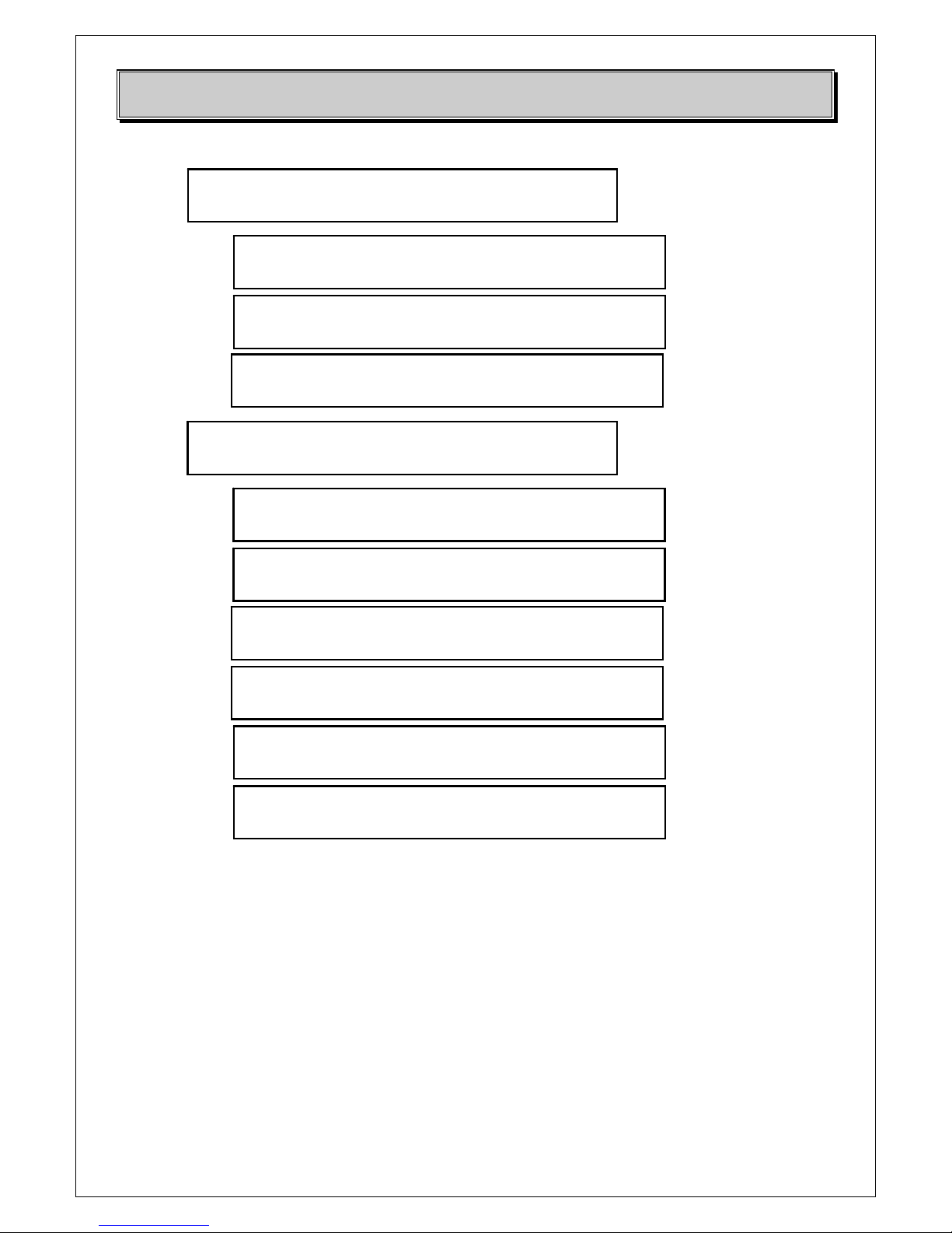
5 Menu Map
CTX VIDEO TRANSMITTER
OL UNLOCK
CTX VIDEO TRANSMITTER
OK
SYSTEM 0.X.X
<CONFIGURATIONS> Æ AUDIO Opt.
AUDIO 1 SUBCARRIER 0.0.0
On
AUDIO 2 SUBCARRIER 0.0.1
On
AUDIO 1 LOW PASS 0.0.2
On
AUDIO 2 LOW PASS 0.0.3
On
AUDIO 1 PREENPHASY 0.0.4
On
AUDIO 2 PREENPHASY 0.0.5
On
AUDIO 1 Deviation 0.0.6
050 KHz
AUDIO 2 Deviation 0.0.7
050 KHz
OUTPUT Options 0.0.X
<AUDIO Options> Æ AUDIO 1 SUBC.
STANDBY
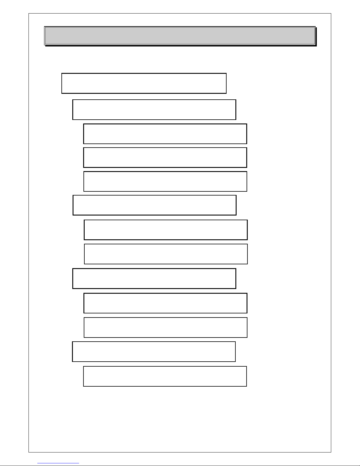
CONFIGURATIONS MENU
DB ELETTRONICA TELECOMUNICAZIONI S.p.A.
Pag. 12/86
VIDEO WHITE CLIPPER 0.1.0
On
VIDEO SYNC LEVEL 0.1.1
30 %
VIDEO LEVEL 0.1.2
0500 mV
AGC type 0.2.3
ALC
IF Precorrector 0.2.4
On
RF Switch 0.2.5
On
AUDIO Options 0.1.X
<VIDEO Options> Æ VIDEO WHITE CLIPPER
VIDEO Carrier Frequency 0.2.0
725250000 Hz
RF LEVEL (ALC) 0.2.1
8.2 Wps
RF LEVEL (MLC) 0.2.2
8.2 Wps
VIDEO Options 0.2.X
<OUTPUT Options> Æ RF Channel
DB ELETTRONICA TELECOMUNICAZIONI S.p.A.
Pag. 13/86
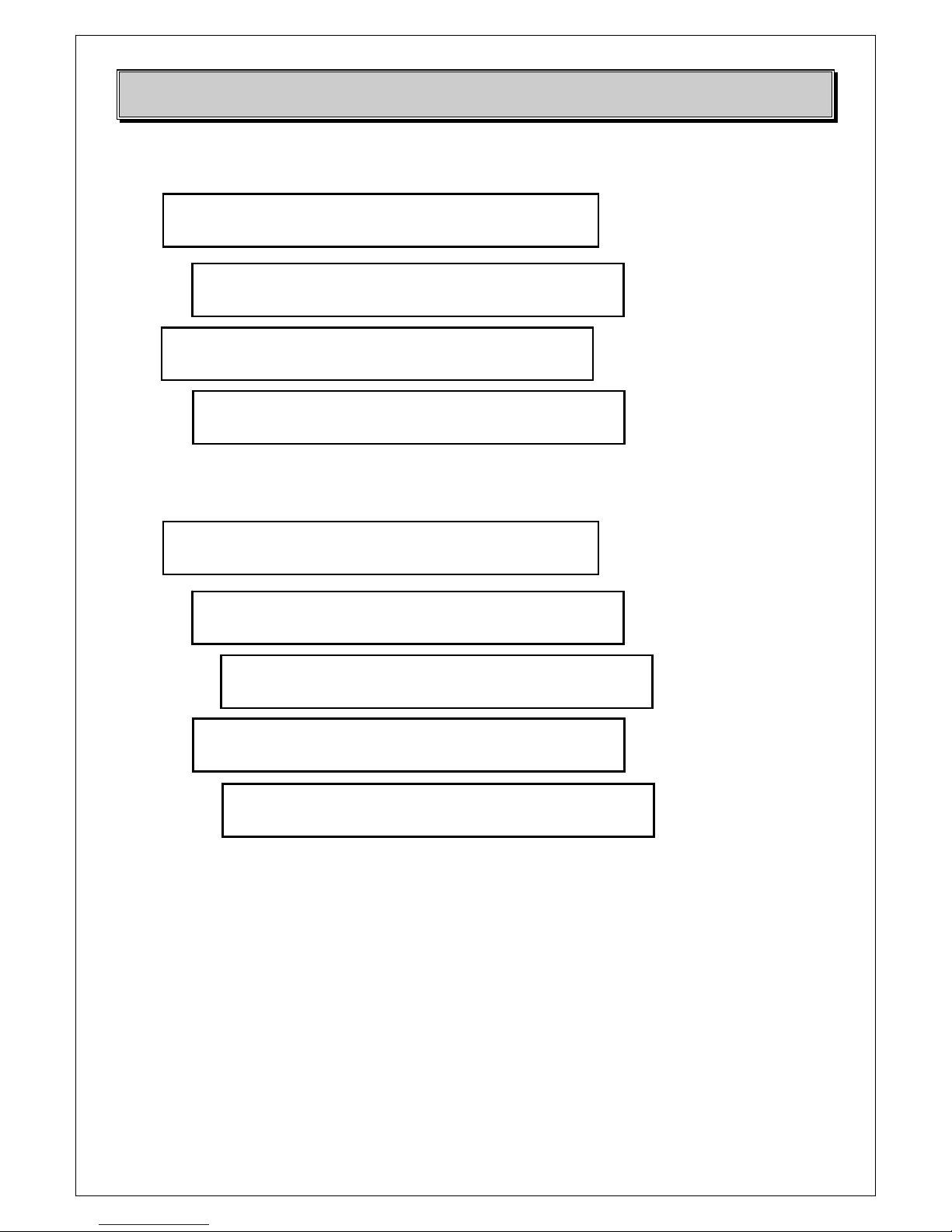
STATUS MENU
CONFIGURATIONS 1.X.X
<STATUS> Æ AUDIO info
VOLTAGE Info 1.0.X
<AUDIO Info> Æ AUDIO levels
AUDIO 1 SC Level: -5dBm 1.0.0
AUDIO 2 SC Level: -5dBm
AUDIO 1 Dev. Level: 50KHz 1.0.1
AUDIO 2 Dev. Level: 50KHz
AUDIO 1 PLL: LOCKED 1.0.2
AUDIO 2 PLL: LOCKED
AUDIO Info 1.1.X
<VIDEO Info> Æ VIDEO levels
1.1.0
VIDEO Amplitude: 1024 mVpp
VIDEO IF Level: -12dBm 1.1.1
VIDEO PLL : LOCKED
VIDEO Info 1.2.X
<OUTPUT Info> Æ Heatsink temp.
Heatsink temperature: 35°C 1.2.0
FWD Power 5.2 Wps RFL Power 0.4 Wps
RF IN Amplif. Stage: -2dBm 1.2.1
VIDEO Carrier Freq.: 725250000 Hz
OUTPUT Info 1.3.X
<VOLTAGE Info> Æ Pwr supply
Meas. +24V: 23.8V 1.3.0
Meas. +15V: 14.9V Meas. -15V: -14.7V
DB ELETTRONICA TELECOMUNICAZIONI S.p.A.
Pag. 14/86
VOLTAGE Info 1.4.X
<ALARMS> Æ List
A
larms List 1.4.0
NO VIDEO INPUT
A
LARMS: 1.5.X
<WARNINGS> Æ List
WARNINGS list 1.5.0
NOT ENABLED
SYSTEM MENU
STATUS 2.X.X
<SYSTEM> Æ SYSTEM Data
SYSTEM Info 2.0.X
<SYSTEM Control> Æ Local/Remote
Remote: 2.0.0
Off
SYSTEM Control 2.1.X
<SYSTEM Info> Æ Standard
NTSC STANDARD 2.1.0
Rev. Hw 1.0 Fw 1.0/1.0
DB ELETTRONICA TELECOMUNICAZIONI S.p.A.
Pag. 15/86
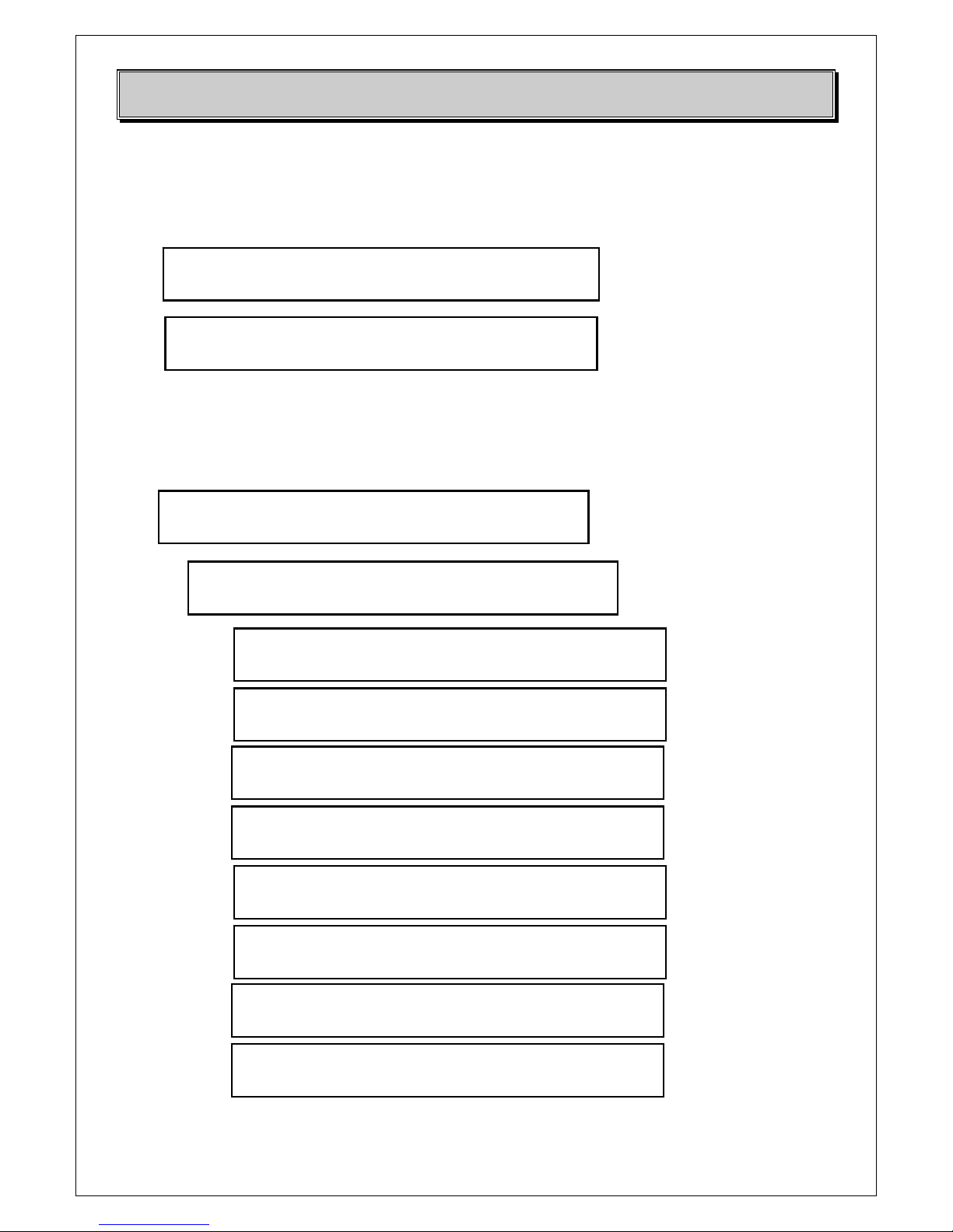
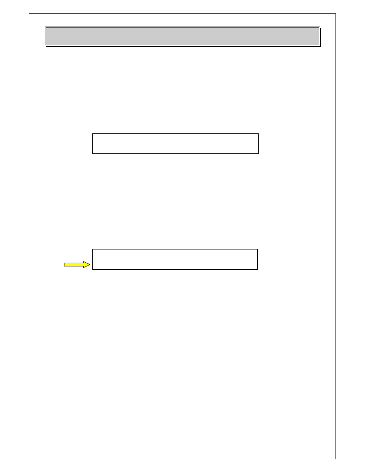
6 Front panel menu
At the switching on of the unit the indication of the Hardware and Firmware versions of the unit
will be showed for some seconds. After this indication the message UPDATING SYSTEM… will
indicate that the unit is uploading all the values for its functioning and the first page that will appear
is the following one:
The indication STATUS OK means that the transmitter is correctly functioning and the frequency is
locked, the ON led on the front panel will be the only one switched on.
The navigation on the menu is done through the front panel buttons on the right of the LCD display.
On each page the indication X.X.X on the top right corner indicates the depth of the navigation:
each submenu starts from page 0.
Each page of the menu indicates on the top the previous sub-menu, and in the second row the actual
selected menu (the one where you will enter pressing the button ►)
To enter a menu it is sufficient to press ►.
For changing a value in a page it is sufficient to press OK: press ▲ or ▼ to modify the value and
press OK to confirm the modification. On the page it will appear a message asking for SAVE or
EXIT: press SAVE to confirm the modification just made (the value will be stored after the
message UPDATING SYSTEM…) or EXIT to disregard it.
6.2 Configurations menu
The Configurations menu allows the setting of the main parameters of the unit (audio 1 and 2
parameters, video parameters).
CTX VIDEO TRANSMITTER
OK
SYSTEM 0.X.X
<CONFIGURATIONS> Æ AUDIO Opt.
DB ELETTRONICA TELECOMUNICAZIONI S.p.A.
Pag. 16/86
AUDIO OPTIONS
Normally the pages related to AUDIO 1 are present, the pages related to AUDIO 2 are
present/enabled only in case the second audio option is present on the unit.
The first page of this menu indicates if the audio subcarrier is switched on or off
The second one indicates if the low pass filter is inserted or not: in case of MONO transmission the
low pass filter is always inserted.
The third page indicates if the preemphasis is inserted or not.
The 4th page indicates the level of the deviation of the audio subcarrier.
VIDEO OPTIONS
In this menu the main parameters related to the video can be set.
The first page indicates if the white clipper is inserted or not.
Normally the default value is ON.
AUDIO 1 SUBCARRIER 0.0.0
On
AUDIO 1 LOW PASS 0.0.2
On
AUDIO 1 PREENPHASY 0.0.4
On
AUDIO 1 Deviation 0.0.6
050 KHz
VIDEO WHITE CLIPPER 0.1.0
On
DB ELETTRONICA TELECOMUNICAZIONI S.p.A.
Pag. 17/86
The 2nd page indicates the sync level: in case the unit is used as stand alone the default value is
100%, while if it is used as driving unit for the amplification part of a complete modular transmitter
the sync level has to be set as follows: the total output signal must be demodulated and the sync
must be set for the optimization of the signal (the sync of the total transmitter will be 100% and the
sync of the CTX has to be set to have it).
The 3rd page indicates the level of the input video signal: the value depends on the video source
used by the customer. Normally the video level is set to 1 Vpp.
OUTPUT OPTIONS
This menu allows to set the parameters related to the RF output signal.
In the first menu page the output frequency can be set with 1 Hz steps. The frequency is expressed
in Hz.
NOTE: in case of change you need to retune also the output filter to have the correct lock and
transmission of the signal. For more information refer to the paragraph related to the
frequency change.
In the 2nd page the RF output level in ALC mode can be set. In case the unit is in ALC mode this
value correspond to the RF output power of the CTX unit.
VIDEO SYNC LEVEL 0.1.1
30 %
VIDEO LEVEL 0.1.2
0500 mV
VIDEO Carrier Frequency 0.2.0
725250000 Hz
RF LEVEL (ALC) 0.2.1
8.2 Wps
DB ELETTRONICA TELECOMUNICAZIONI S.p.A.
Pag. 18/86
If the transmitter is in MGC mode the same page will allow the change of the RF output power in
MGC mode and the indication will be RF LEVEL (MLC).
In the 3rd page it is possible to choose the mode of the AGC (Automatic Gain Control) of
functioning between ALC (Automatic Level Control) and MLC (Manual Level Control).
In the 4th page it is possible to decide if the IF Precorrector must be inserted or not.
In the 5th page it is possible to decide if the CTX is used as modulator or as amplifier unit. If the
CTX is used as complete modulator (and so to modulate the signal and amplify the 0 dBm up to
5W) the RF Switch must be OFF (internal generator) while if the CTX is only used as amplifier of
an external signal the RF Switch must be ON.
AGC type 0.2.3
ALC
IF Precorrector 0.2.4
On
RF Switch 0.2.5
On
DB ELETTRONICA TELECOMUNICAZIONI S.p.A.
Pag. 19/86
6.3 Status menu
The Status menu shows the readings of the audio and video parameters moreover the status of the
PLL (locked or unlocked).
AUDIO INFO
In this submenu all the information related to the audio signal (audio 1 and audio 2 if present) are
indicated: Audio subcarrier level, deviation level, if the PLL is locked or not.
VIDEO INFO
In this submenu all the information related to the video signal are indicated: Amplitude level, IF
level, if the PLL is locked or not.
OUTPUT INFO
In this submenu all the information related to the normal functioning of the unit are indicated:
heatsink internal temperature, forward and reflected power, RF input amplifier stage, frequency.
A
UDIO 1 SC Level: -5dBm 1.0.0
AUDIO 2 SC Level: -5dBm
A
UDIO 1 Dev. Level: 50KHz 1.0.1
AUDIO 2 Dev. Level: 50KHz
AUDIO 1 PLL: LOCKED 1.0.2
AUDIO 2 PLL: LOCKED
1.1.0
VIDEO Amplitude: 1024 mVpp
VIDEO IF Level: -12dBm 1.1.1
VIDEO PLL : LOCKED
Heatsink temperature: 35°C 1.2.0
FWD Power 5.2 Wps RFL Power 0.4 Wps
RF IN Amplif. Stage: -2dBm 1.2.1
VIDEO Carrier Freq.: 725250000 Hz
DB ELETTRONICA TELECOMUNICAZIONI S.p.A.
Pag. 20/86
VOLTAGE INFO
In this submenu the measures related to the internal voltages are indicated. Normally the correct
values that should be present when the unit is functioning in the proper way are the ones indicated
here below:
ALARMS
The possible cause of alarm status are indicated in this page.
WARNINGS
The messages related to the status of the equipment or cause of blocking of the output not related to
an alarm.
6.4 System menu
The System menu allows the change of the mode from LOCAL to REMOTE and the visualization
of the main data of the unit (standard, hardware and firmware versions).
SYSTEM CONTROL
In this page it is possible to set the unit in the REMOTE or LOCAL mode. Normally it is set in
REMOTE OFF. When the REMOTE mode is set no modification of the parameters of the unit is
allowed from the front panel.
SYSTEM INFO
In this page it is possible to visualize which is the actual analog standard of transmission (PAL /
NTSC / SECAM). In the second row it is also indicated the Hardware and the Firware versions.
Remote: 2.0.0
Off
NTSC STANDARD 2.1.0
Rev. Hw 1.0 Fw 1.0/1.0
Meas. +24V: 23.8V 1.3.0
Meas. +15V: 14.9V Meas. -15V: -14.7V
DB ELETTRONICA TELECOMUNICAZIONI S.p.A.
Pag. 21/86
7 Frequency change
In case of change of the transmitter operating frequency the following units need be adjusted:
1) Driver unit: the setting of the TX output operating frequency is made from the front panel
display CONFIGURATIONS MENU -> OUTPUT OPTIONS -> VIDEO CARRIER
FREQUENCY.
2) Output BandPass-Notch Filter: it needs to be readjusted to obtain a clean output spectrum in
order to meet international requirements.
All amplification circuits are broadband (from 470 to 860 MHz), then the power amplifiers don’t
need any adjustment.
WARNING: In any case, any equipment modification or variation must be made only with
DB Elettronica Telecomunicazioni S.p.A. written authorization, otherwise voiding the
warranty.
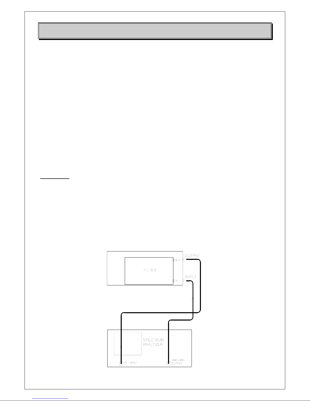
To adjust the Output Band Pass filter, in case of adjustments of less than
Otherwise remove the bottom cover of the CTX unit and connect the TRACKING output connector
of a spectrum analyser with the FILTER INPUT connector and then connect the FILTER OUTPUT
connector with the RF INPUT of the analyser as indicated in the picture here below:
DB ELETTRONICA TELECOMUNICAZIONI S.p.A.
Pag. 22/86
CN1
TC1 T C2 TC3 TC4
CN2
L6
L1
L2 L3 L5
L7
L8
L4
CN 1 Smb
( IN )
L1
TC1
L8
TC4
CN 2 Smb
( OUT )
L2
TC2
L3
TC3
L4
L5
L7
L6
2 coil
10pF 10pF 10pF
10pF
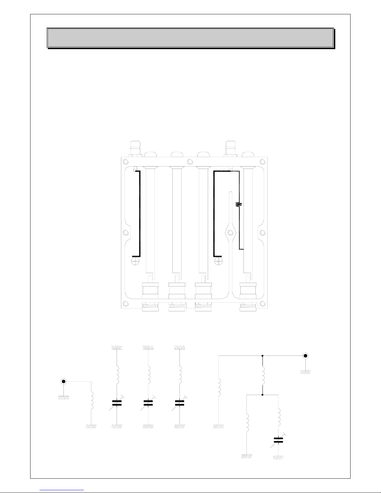
Through the trimmers you see on the front panel hole, it is possible to have access at the variable
capacitors (TC1, TC2, TC3, TC4) regulating the bandwidth and the attenuation of the filter (using a
screwdriver). Rotate slowly these screw variable capacitors setting the center frequency of the Band
Pass Filter on the desired frequency and adjust the filter as in figures below.
Fig. 7.1 – BPF/O LAYOUT
Fig. 7.2 – ELECTRICAL DIAGRAM
DB ELETTRONICA TELECOMUNICAZIONI S.p.A.
Pag. 23/86
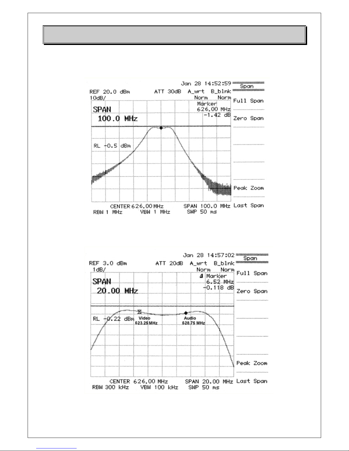
Fig. 7.3 - BPF/O ADJUSTING - SPECTRUM ANALYZER VIEWS (UHF CASE)
INSERTION LOSS < 1.5 dB
The pictures refer to the UHF case: please do the same in case of VHF functioning of the unit.

DB ELETTRONICA TELECOMUNICAZIONI S.p.A.
Pag. 24/86
8 Audio and Video modulator board
This board accepts the audio and video signals and modulate them in order to have the IF signal on
the output. In this board it is possible to make all the adjustments related to the optimization of the
video and audio signals, and the adjustments related to the standard choosen by the front panel.
Video modulation
The essential functions of this part are the following:
* DC restoration circuit, fixing and maintaining a constant operating point of the modulator;
* Additional video signal processing comprising corrections of linearity, differential phase,
differential gain and white clipping;
* Proper amplitude modulation of the IF vision carrier with the formerly processed video signal.
* The modulation is effected in a Double Balanced Mixer giving at the output a double-sideband
spectrum;
* The required Vestigial-Sideband spectrum is achieved by the successive SAW filter;
* The generation of the IF Vision carrier is made through a quartz, phase-locked to reference signal;
* The combination of IF Vision signal with IF sound signal.
Audio modulation
The audio modulation part performs the following functions:
* Linear correction of the audio signals (pre-emphasis, low pass filter);
* FM modulation of the carriers (A1, A2);
* Combining of the two IF sound FM modulated carriers (in case of two carrier system).
DB ELETTRONICA TELECOMUNICAZIONI S.p.A.
Pag. 25/86
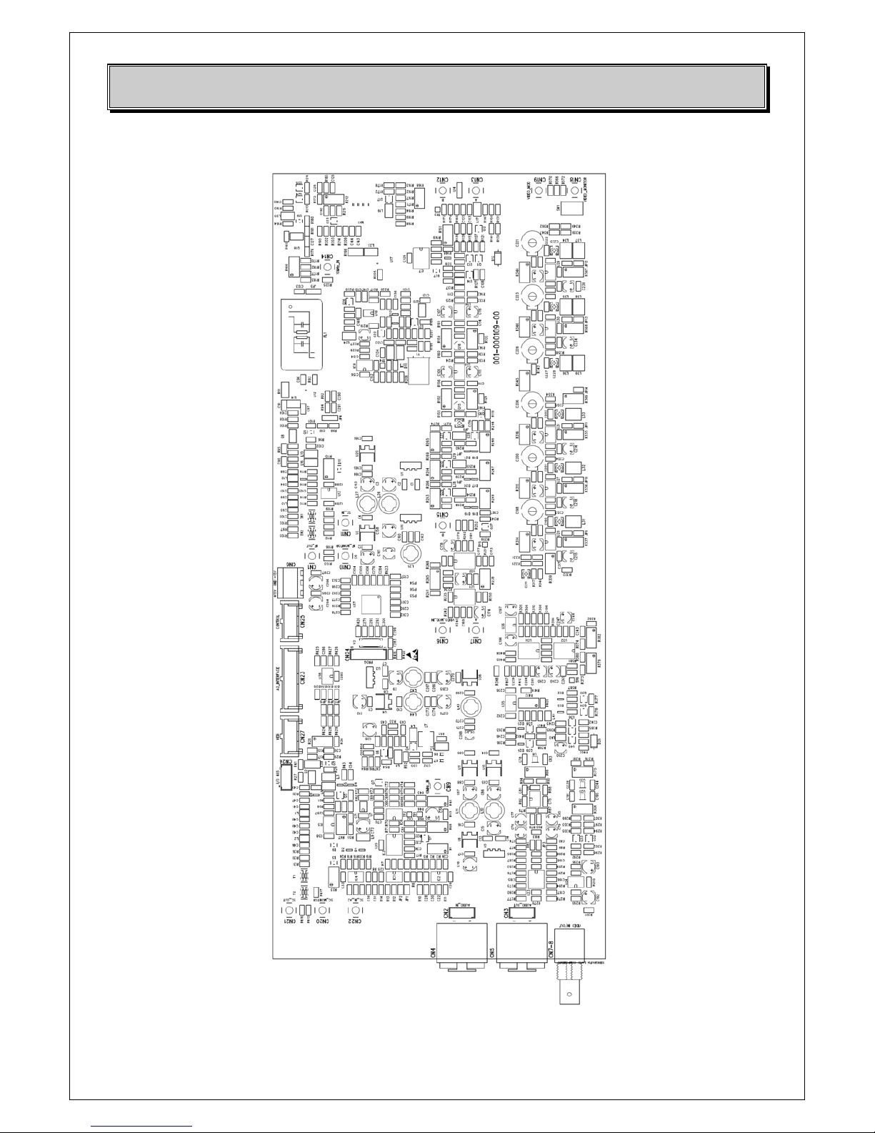
Audio and video modulator layout
DB ELETTRONICA TELECOMUNICAZIONI S.p.A.
Pag. 26/86
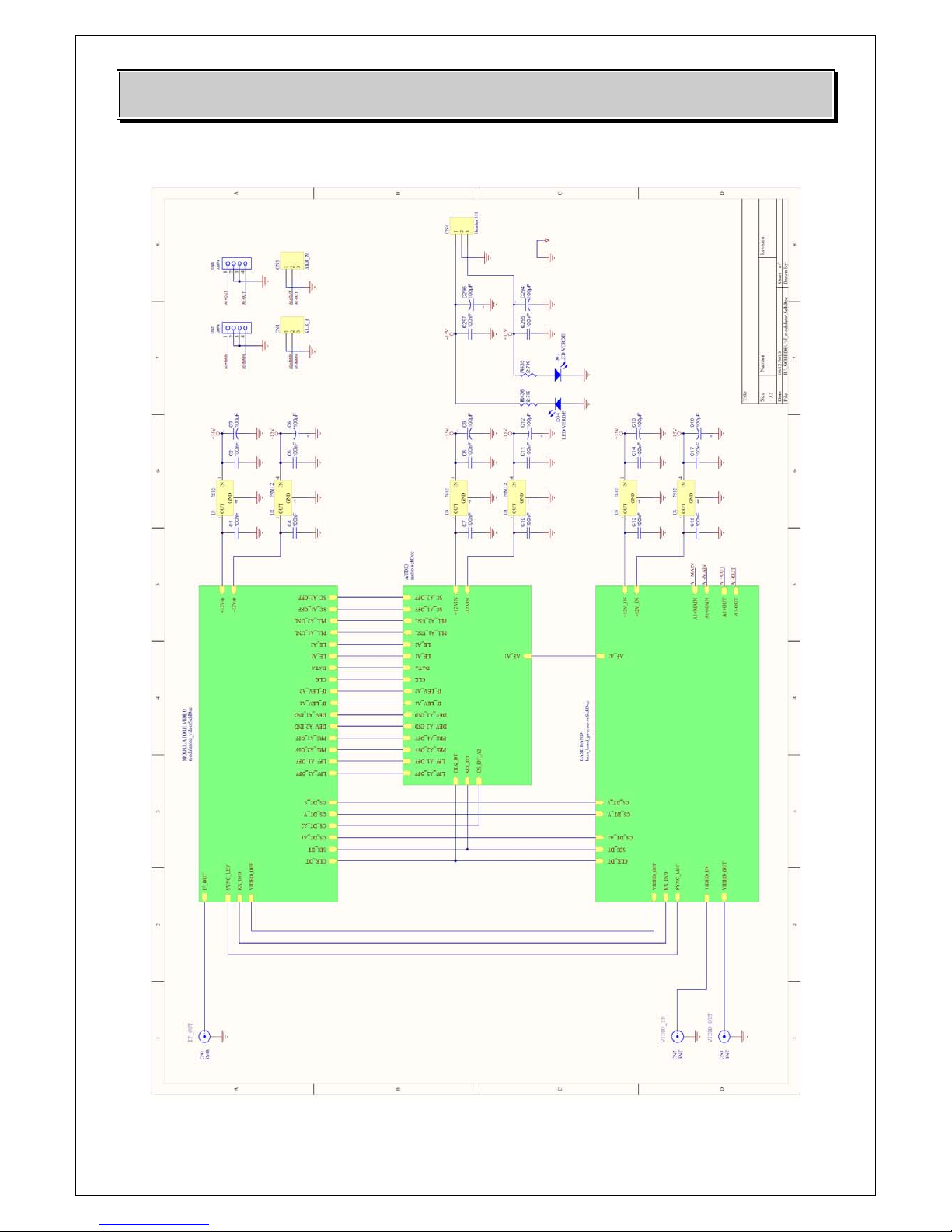
Electrical diagrams
 Loading...