

Page 1
TM
EUPHORIA
EDSP4-31BT
31 Band Digital Sound Processor
with Built-In Amplifier
USER MANUAL
Page 2

Introduction
Optimal Product Choice
Congratulations on your purchase of a DB Drive state-of-theSound Processor. Your selection of a DB Drive car audio product
indicates a true appreciation of true musical reproduction.
Whether adding to an existing system or including your DB
Drive processor in a new system, you are certain to notice
immediate performance benefits.
Product Commitment
DB’s engineering professionals harnessed years of expertise,
experience and passion, coupled with exhaustive testing and
creative design to develop the optimal product and performance
for your musical enjoyment. This is our commitment to you. It’s
what you deserve and have come to expect from DB DRIVE.
We appreciate the confidence and look forward to your positive
experience.
Keep Your Sales Receipt
Take this time to attach your sales receipt to the manual and put
in a safe place. In case of any unforeseen reason this product
may need warranty service, your receipt will be necessary to
establish purchase date.
To get the Maximum performance out of your stereo system,
we recommend using 100% authentic DB Drive electronics and
DB LINK wiring and accessories. Matching DB Drive amplifiers
and Speakers with your state-of the art electronics purchase
is critical to optimize your system’s performance. Wiring is
the lifeblood of a system, make sure your audio system has
adequate current and signal transfer it deserves and needs.
DB Link has it all, from wiring rolls; Speaker, power, ground and
remote to amplifier kits, RCAs, and Fuse holders, distribution
blocks and battery connectors.
Precautions
Warning: To prevent the unit from any damage, please keep the
EDSP4-31BT in a dust and moisture free environment.
If unit is exposed to water and/or any liquid, please remove the
power cables immediately and let it dry completely. Please do
not open the unit there are no user serviceable parts inside.
Exposure to high power sound system can cause hearling loss or
damange. Listening to your system at loud levels while driving
will impair your ability to hear traffic sounds and emergency
vehicles. Use common sense when listening to your system.
Recommendation
A processor's performance is only as good as its installation.
Proper installation will maximize the system’s overall
performance. It is recommended that you have our product
installed by an authorized DB Drive retailer. However, if you
decide to install it yourself, please carefully read through this
manual and take your time to do a quality installation.
Packing List
Every package will include the following items:
EDSP-31BT (unit)
User Manual
Warranty Card
2m USB2.0 Cable
In/Out Speaker Cable
1PC
1PC
1PC
1PC
1PC
Page 3

TM
EUPHORIA
Contents
1. Features...................................................................................... 6
1.1 Product Characteristics ..........................................................6
1.2 Input & Output Side Panels ...................................................7
1.3 Software Introduction .............................................................8
2. System Connections ..................................................................8
2.1 Unit Configuration ....................................................................8
2.2 Unit Connection ........................................................................9
2.3 Low Level RCA input/output Indication .............................10
2.4 USB2.0 Port ...............................................................................10
3. Software Operation .................................................................. 11
3.1 Software Installation ...............................................................11
3.2 Power OFF/ON ..........................................................................11
3.3 Software Interface ...................................................................12
3.4 Audio Input Signal Selection .................................................13
3.5 Output Channel Configuration ..............................................13
3.6 Output Channel Settings ........................................................14
3.7 Output Delay Adjustments ....................................................17
3.8 Signal Equalizer Adjustments ...............................................17
3.9 Signal Equalizer & Crossover Operation ............................18
3.9.1 Crossover Operation ....................................................... 18
3.9.2 Equalizer Operation ......................................................... 19
4. Software Operation .................................................................. 20
EDSP4-31BT
31 Band Digital Sound Processor
with Built-In Amplifier
4.1 Saving & Deleting Adjustment Settings ............................20
4.1.1 Saving Output Configuration to Computer ............. 20
4.1.2 Saving the EDSP4-31BT Settings to Device ..........21
4.1.3 Restore Saved Settings .................................................. 22
4.1.4 Deleting EDSP4-31BT Presets ................................... 23
4.2 Operation Settings ...................................................................24
4.2.1 Mixer Settings: ................................................................... 24
4.2.2 Options Menu: ................................................................... 25
5. Troubleshooting ........................................................................ 26
6. Appendix: Product Warranty Information ............................. 27
Page 4
1. Features
1.1 Product Characteristics
• OEM System integration sound processor
• Perfect for OEM factory speaker tuning
• 48-bit DSP with floating point processing
• Low and/or High-level inputs
• Sources: Bluetooth, High level input, Stereo RCA Analog
inputs
• Infinitely adjustable digitally processed channels
• Built in 4 x 75W Class AB amplifier with infinitely
adjustable digitally processed channels
• 31 Bands of independent equalization per channel
• Real time Parametric and Graphic equalizer
• Frequency range: 20Hz ~ 20KHz, 1Hz steps
• Adjustable Gain: -12.0dB ~ +12.0 dB for all 31 bands
• High pass, low pass, and bandpass, independent filters
per channel
• Infinite Filter crossover points between 20Hz – 20KHz
• Crossover Filter Slopes selectable at : 6db, 12dB, 18dB,
24dB, 30dB, 36dB, 42dB, 48dB
• Up to 15ms of variable time delay per channel
• 0 deg. or 180 deg. direct phase adjustment per channel
• Complete System control and advance tuning through
smartphone App connection or PC
• APP is compatible with both IOS and Android
• Tuning preset memory
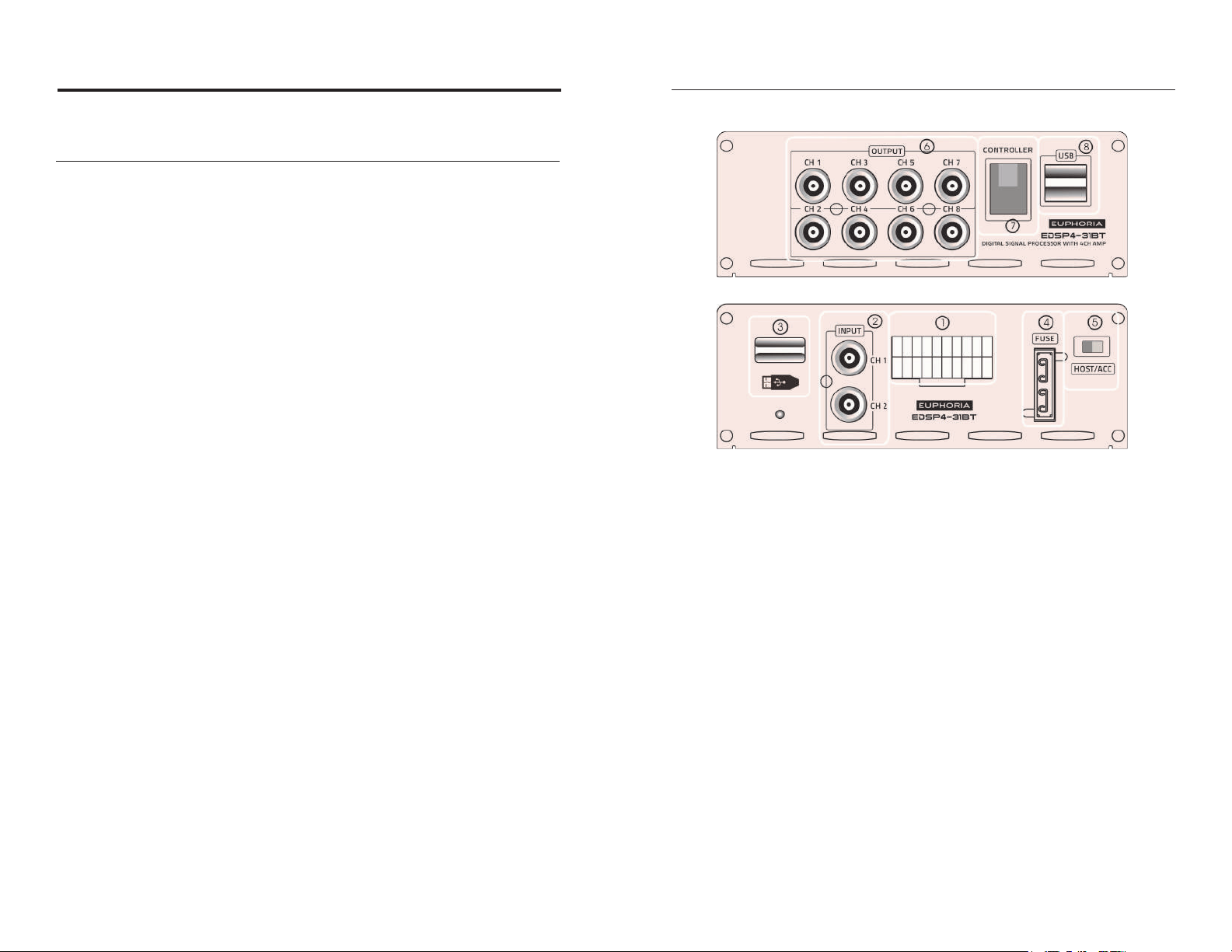
1.2 Input & Output Side Panels
Figure 1.2.1
1. High Level Input / Speaker Output
2. Low Level RCA Input
3. USB Interface
• USB Storage Device - Music Playback Interface
4. Protection Fuse
5. HOST/ACC Switch
• Move switch to “HOST” and the unit will power on
with high level input signal.
• Switch to “ACC” and product will power on with
remote in.
6. DSP OUTPUT - Low Level RCA Output
7. Dash Source Controller (sold separately)
8. USB USB2.0 Interface for PC Tuning
6 7
Page 5

1.3 Software Introduction
EDSP4-31BT PC Software Setup
(Check Section 3 for complete Software Operation information)
1. Unit automatically detects hardware after connecting via
USB cable to a computer.
2. A minimum display resolution of 1280x760 is required
for full-screen view.
3. Software only compatible with windows operating
system.
2. System Connections
2.1 Unit Configuration
Connection options illustrated above in Figure 2.1.1
1. Connect aftermarket radio to the EDSP4-31BT using the
RCA low level input connection.
• You can also stream music from your mobile phone
to the EDSP4-31BT using a Bluetooth connection.
2. Use the in/out speaker cable to connect the factory car
stereo to the EDSP4-31BT to upgrade the audio system
tuning (optional). Use Low Level RCA Output CH7 and CH8
to install a bass amplifier or active subwoofer.
2.2 Unit Connection
Figure 2.2.1
The following table shows the configuration of input/output 1
on the panel illustrated above in Figure 2.2.1:
Output Output Output Output Input Input Input Input GND +12V
FL+ FL- FR+ FR- FR- FL- RL- RR-
Figure 2.1.1
white white
/ black
RR+ RR- RL+ RL- FR+ FL+ RL+ RR+
purple purlple
/ black
Output Output Output Output Input Input Input Input Blue Red
Table 2.2.1
gray gray /
black
green green
/ black
gray /
black
gray white green purple REM ACC+
white
/ black
green
/ black
purple
/ black
black yellow
8 9
Page 6

• REM input: While the switch is set to ACC the unit will
turn on when the12V accessory source is connected to
the ACC+ input; When switch is set to HOST and the unit
detects the audio signal from the factory radio outputs
connected to the two high level input lines of FL+/FL- the
unit power will on.
• If you are using RCA Low Level Input while the toggle
switch is set to ACC then use the REM or ACC+ cables to
power on the EDSP4-31BT.
3. Software Operation
3.1 Software Installation
• Computer tuning software is available for download at
euphoriacaraudio.net
• Operating Systems: Windows XP / Vista / WIN7 / WIN8
operating system.
2.3 Low Level RCA input/output Indication
When using the Low Level RCA Input shown as input 2 on
the panel illustrated in Figure 2.2.1:
• The maximun capacity of these inputs is 10V from an
aftermarket radio.
• CH1-2, CH3-4 and CH7-8 outputs will recieve signal
from Low Level RCA input. CH5 and CH6 are null. CH7-8
will function as subwoofer outputs only.
2.4 USB2.0 Port
• Download and follow the on-screen prompts to install
software, Once the download is finished, double-click the
installation file to open the application.
3.2 Power OFF/ON
Double-click the EDSP4-31BT application icon while the
USB cable is connected to the powered EDSP4-31BT. The
software application will open the and the main interface
display will appear.
Figure 2.4.1
For EDSP4-31BT tuning, connect USB cable to computer via
USB USB2.0 Interface for PC Tuning 8 (refer to Figure 1.2.1
in Section 1).
Figure 3.2.1
10 11
Page 7

Note: EDSP4-31BT can only be connected to a computer
with a USB cable.
• Ensure that EDSP4-31BT is powered on while the USB
cable is connected to a computer.
• The computer will automatically install and update the
device drivers.
• The EDSP4-31BT software will automatically sink- up
with the on-screen GUI. At this point, in the top left
corner, the Input Signal Selection and Connection Status
area will indicate green “connected” state.
3.3 Software Interface
As shown above in Figure 3.3.1, the software interface of the
EDSP4-31BT GUI is divided into 6 areas:
1. Input Signal Selection and Connection Status.
2. Mixer
3. Main Menu
4. Crossover & Equalizer Adjustments
5. Time Delay Adjustments
6. Output Channel Configuration
3.4 Audio Input Signal Selection
• While connected to a computer, select the appropriate
audio input source in the Input Signal Selection and
Connection Status area.
• The input selections are High Level, AUX, Phone and
Player. The audio input signal can be selected from the
audio input drop-down menu. The default source is high
level.
• Each input source signal gain can be adjusted in the Mixer
area. The adjustable range is 0-40.
3.5 Output Channel Configuration
Step 1: Select the channel you want to edit in the Output
Channel Configuration area of the interface.
- CH1 - 6 are used for full range frequencies
- CH7 - 8 are used for low frequencies.
Step 2: You can switch between channels to individually adjust
Figure 3.3.1
parameters respectively.
Step 3: Repeat the process with each channel that you wish to
adjust.
12 1312 13
Page 8

Note: The crossover and equalization parameters for each
channel will vary depending on the specific channel and
adjustments made in respect to the equipment used.
• Phase: Select the phase button to alternate between
positive phase (0°) and inverted (180°).
Figure 3.6.2
• Delay: The 3 possible units of delay are milliseconds
(0.000~7.350ms), centimetres (0~254mm), and inches (0100in)
Figure 3.5.1
3.6 Output Channel Settings
In Figure 3.5.1, six output channels are being used. The most
commonly used channel output settings are displayed. Users
can customize the speaker type of each output channel. The
output gain, delay, input type, mute and phase settings can all
be adjusted for each seperate channel.
• Gain: The output volume for each channel is controlled by
sliding the fader located below each channel label with a
range of -59dB to 6dB. There is also a master volume of all
output located in the middle far-left of the interface. The
total master volume range is -39dB to 6dB.
• Mute: By selecting the mute button, you can turn the
music signal for the selected channel ON/OFF
• Output Type: The EDSP4-31BT processor output signal
can be configured to any sound field point and speaker
type. The system factory defaults is set to 4.1 full-range
passive mode.
CHANNEL OUTPUT
CH1 Front / Left
CH2 Front / Right
CH3 After A Left-Field
CH4 After A Right-Field
CH7 Left Bass
CH8 Right Bass
Figure 3.6.3
Users can customize the speaker type for each output channel
by following the steps below:
Step 1: Click “Reset Output” button located on the right side
Figure 3.6.1
of the Output Channel Configuration area. Select the “Emptied”
option to set output types on all channels to NULL and
return to the main interface.
14 15
Page 9
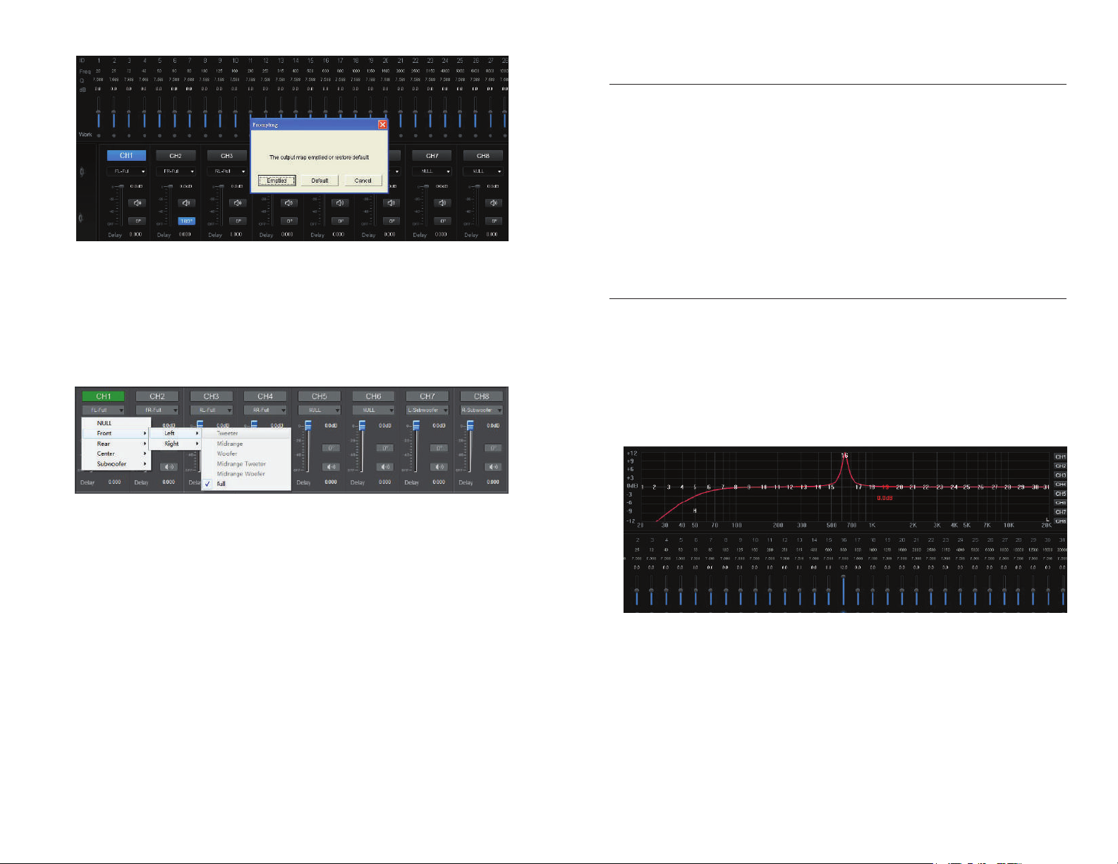
Figure 3.6.4
Step 2: Beneath each channel number is a drop-down
button. Click on the button then select the output type being
used for each specific channel.
3.7 Output Delay Adjustments
The Output Delay Adjustments area is located left of the Output
Channel Configuration area. To make adjustments to delay
settings select the desired channel in the Output Channel
Configuration area then input a value for the delay to be added
to the corresponding speaker.
3.8 Signal Equalizer Adjustments
Changes to the equalizer settings can be made in the Crossover
& Equalizer Adjustments area located above the Output Channel
Configuration & Output Delay Adjustments areas, as shown
below:
The options for output configuration will be determined by
what the user has selected for currently assigned channels
in the signal path. If a desired option is greyed out, then
check any previously configured channels and ensure
appropriate output types are set.
Front » Left, Right » High / Mid / Low / Mid-High / Mid-Low / & Full Frequency
Rear » Left, Right » High / Low / & Full Frequency
Center » High-Frequency, Low Frequency & Full Frequency
Subwoofer » Subwoofer Right, Subwoofer Left
Figure 3..8.1
Adjustments: The EDSP4-31BT GUI allows the user to easily
make changes. Use your cursor to drag the slider of the
desired frequency band up or down. Whenever the parametric
Step 3: After the user has selected all the output signal
paths, click the “Lock Output“ button to lock the channel
equalizer curve is available, each corresponding input
parameter value will be adjusted in real time.
output configurations and preven accidental changes.
16 17
Page 10

Channel Selection: You can choose to adjust the EQ of a
specific channel by slecting a channel from the Output Channel
Configuration area. The selected channel that is currently being
edited will appear in a blue highlighted state.
Reset EQ: This operation will change the equalizer gains to
0db on all frequencies for the selected channel.
Frequency: You can make adjustments to this setting via direct
input value or by scrolling up and down with the mouse wheel
to adjust low-cut or high-cut frequency. The adjustment range
is 20Hz ~ 20KHz.
Slope: You can set the slope of the frequency curve to 6dB/
Oct, 12dB/Oct, 18dB/Oct or 24dB/Oct. You will not be able to
make changes to the type setting if slope is set to 6dB/Oct.
Instead, the type setting will automatically be set to NULL.
3.9 Signal Equalizer & Crossover Operation
3.9.1 Crossover Operation
Changes to the crossover frequency, type and slope settings
can be made in the Crossover & Equalizer Adjustments area
located above the Output Channel Configuration & Output Delay
Adjustments areas, as shown below:
3.9.2 Equalizer Operation
Addition options for equalizer and crossover settings can be
found in the Output Channel Configuration area located on the
far right. These settings allow for quick and easy operation.
Figure 3.3.8
Reset Output: Selecting the Reset Output button will re-
configure the output map of the selected channel. You can
Figure 3.9.1
clear the mapping by selecting “Emptied“ or reset the mapping
to default by choosing “Default“ from the pop-up dialog box
Crossover Type: click drop-down button to select from
Linkwitz-Riley, Bessel and Butterworth for both High-pass
and Low-pass filters.
that appears. If the output configuration is emptied, there will
be no output signal to any channel speaker. This option is used
to restore the output channels for a new system configuration.
18 19
Page 11

Lock Output: This button is uesed to lock or unlock the output
map all channels from CH1 to CH8. While the channels are
locked, the Lock Output button will be highlighted blue and
you will not be able to select the drop-down arrow for output
types in the Output Channel Configuration area.
Step 3: Assign the preset a name. This must be done before
disconnecting the EDSP4-31BT USB connection from
computer.
4.1.2 Saving the EDSP4-31BT Settings to Device
Link L&R: After selecting the Link L&R, a pop-up dialog will
appear with two options to choose from. You will be able to
copy EQ settings from either left-to-right or right-to-left
between two respective channels. This function is used to
simplify the EQ process for most systems
4. Software Operation
4.1 Saving & Deleting Adjustment Settings
Select the Secne button located in the top-right to open the
drop-down menu in order to save adjustment settings.
Step 1: Select the “Secne” button located in the top-right to
open the drop-down menu
Step 2: Then, select Save As Machine Preset to save all setting
to the EDSP4-31
Step 3: Select a preset number from the left column, as shown
below in Figure 4.2
Figure 4.2
Step 4: Rename the preset in the right column to identify the
stored data.
Figure 4.1
4.1.1 Saving Output Configuration to Computer
Step 1: Select the Secne button located in the top-right to
open the drop-down menu.
Step 2: Then, select Save As PC Preset to save all settings to
your computer for future reference.
Figure 4.3
20 21
Page 12

Figure 4.4
Step 5: Once the preset has been renamed, select the “Save”
button on the bottom of the pop-up menu and wait until the
Data transmission progress bar finishes.
4.1.4 Deleting EDSP4-31BT Presets
Step 1: Select the Secne button located in the top-right to
open the drop-down menu in order to delete preset settings
and a menu box will appear.
Figure 4.1
Figure 4.5
After data transfer is completed, the process is finished.
Figure 4.6
Step 2: Select preset setting you want to delete then select
4.1.3 Restore Saved Settings
the “Delete” button, a dialog box will appear for confirmation.
You can restore Saved Settings from either the EDSP4-31BT
or saved files on your computer.
Load Machine Preset: Loads the adjustment data that is
currently stored on the EDSP4-31BT.
Load PC Preset File: Loads the adjustment data files that are
currently stored on the computer.
Figure 4.7
22 23
Page 13

Step 3: Once you select “Yes“ to confirm the operation, the
preset setting that you chose to delete will no longer have a
preassigned name.
Figure 4.8
4.2 Operation Settings
4.2.1 Mixer Settings:
4.2.2 Options Menu:
Click the options button located in the Main Menu area up in
the top right of the interface to reveal the options drop-down
menu.
Figure 4.9.1
Click Mixer button located in the top right of the interface in
the Mixer area to adjust relevant parameter settings.
Figure 4.9
24
Language Settings: You can choose between Chinese &
English.
Firmware Update: When you select this option a dialog box
will appear that will allow you to browse your computers file
directory and choose the update file for latest version of the
software. The updated file can be found on our official website
at https://dbdrive.net. Alternatively, you can contact us via
email at support@dbdrive.net for more information.
About: This option will display the version of software that you
2524 25
Page 14

are currently running along with copyright information.
Restore Factory Settings: Clicking “Restore Factory Settings”
will allow you to restore the data on the device to default
settings from the factory. Please save any adjustment settings
to your PC if you want to access them in the future.
5. Troubleshooting
TM
EUPHORIA
LIMITED WARRANTY
We have established certain guidelines to help remedy
possible troubles that you may come across when using the
EDSP4-31BT and it’s accompanying software. If you have any
issues during normal operation please try the steps to find a
resolution.
In many cases, troubles can be eliminated by verifying
proper wiring configurations and using appropriate settings
adjustments for the respective audio equipment being used in
the system.
If there is no sound ouput please check the following:
• Make sure that the Power LED is on and blue.
• Power on any external amplifiers.
• Volume/Gain from source must be on.
• Verify the configuration of wiring in the audio system.
- Refer to the user manuals of any audio
equipement being used to ensure proper
installation.
• Ensure that no outputs or channels have been
muted
If issues persist please contact your authorized DB Drive
Euphoria Dealer or email us at support@dbdrive.net.
DB Drive
in the U.S.A. from an authorized DB Drive
TM
warrants any Euphoria products purchased
TM
Euphoria
dealer. All products are guaranteed to be free of defects
in material and workmanship under normal use and for
a service period of one (1) year when purchased over the
counter. This warranty applies to the original purchase
only.
DB Drive
TM
will either repair or replace any unit that has
been found to be defective under the warranty provided
within one (1) of purchase.
DB Drive
DB Drive
TM
Euphoria products installed by an authorized
TM
Euphoria dealer will receive a one (1) year
warranty.
Warranty periods do not extend to units having been
subjected to customer misuse, abuse, neglect, or
accident. Products that show evidence of having been
altered, modified, or serviced without authorization, will
void any warranty.
To obtain service under warranty please contact your
retailer or visit our website at www.dbdrive.net for more
details.
26 27
Page 15

TM
EUPHORIA
DB Research L.L.P. • 302 Hanmore Industrial Parkway • Harlingen, TX 78550
Ph: (877) 787-0101 • Fax: (956) 421-4513
find help at suppport@dbdrive.net
Designed and Engineered in the U.S.A.
 Loading...