

Page 1

www.dbdrive.net
DUE TO CONTINUOUS IMPROVEMENT OF THE PRODUCT THE SPECIFICATIONS ARE SUBJECT TO CHANGE WITHOUT NOTICE.
Page 2

WORLD RECORD BREAKING TECHNOLOGY
1. AMPLIFIERS’ SPECIFICATION
1-1. AMPLIFIER
A7 PRO2.5K
625 Watts
1250 Watts
2500 Watts
01
10 ~ 15Volts
20Hz ~ 10KHz
< 100dB
250 <
6V ~ 0.2V
35Hz ~ 10KHz
0 ~ 9dB
10Hz ~ 50Hz
0 ~ 180 degree
Yes
Yes
1 ohm
INPUT
Connect RCA output cables from the headunit to
OKUR Competition amplifiers’ RCA Input
OUTPUT
Is used when connecting multiple amplifiers
POWER & PROTECTION INDICATOR
Power LED - Green-lit shows normal operation.
Protect LED - RED-lit shows general malfunction,
faulty connection or thermal protection.
Load
4ohm
2ohm
1ohm
Voltage & THD
14.4 volts & 1%
14.4 volts & 1%
14.4 volts & 1%
Working Voltage
Frequency Response
Signal to Noise Ratio
Damping Factor
Low Level Input
Low Pass Filter Variable
(@ 24dB Slope)
Bass Boost @ 45Hz Variable
Subsonic Filter
(@ 24dB slope) Variable
Phase Shift Variable
Remote Level Control
RCA line Output
Minimum working impedance
2. AMPLIFIER’S CONTROL & CONNECTION.
Page 3

02
GAIN (6V ~ 0.2V)
Matching the output voltage of the headunit’s RCA
line-outs to OKUR amplifiers’ input section.
SUBSONIC FILTER (10Hz ~ 50Hz @ 24dB/Oct)
Control the high Pass point for the speaker outputs
to eliminate extreme low frequencies that can
damage your speakers.
BASS BOOST (0~9dB @ 45Hz)
It boosts the bass 0 ~ 9dB
REMOTE LEVEL CONTROL PORT
This port is for connecting remote gain level control
LOW PASS FILTER (35Hz ~ 10KHz @ 24dB/Oct )
Controls the low pass point for the speaker outputs.
PHASE (0 ~ 180 degree )
It controls phase from 0 ~ 180 degree.
+12V (POWER CONNECTION)
This must be connected to the fuse positive terminal
(+12V) of the battery.
Recommenede wire is 4 gauge or thicker
Check the battery voltage.
GND ( GROUND CONNECTION )
It is connected to the Negative or ground cables of
the vehicle.
Recommenede wire is 4 gauge or thicker
REM (REMOTE)
It is connected to switched +12V with a trigger cable
coming from the head unit.
SPEAKER OUTPUTS
It connects amplifier’s terminal to subwoofer
speakers.
Minimum speaker wire is 12 gauge.
Minimum impedance is 1 ohm for single unit.
Linked connection’s minimum impedance is 2 ohm.
3. INSTALLATION
In case you install the amplifier by yourself, please read owner’s manual very carefully before your installation
Please take all steps into consideration or, you can have DB Drive or DB Research’s authorized dealer to check
installation and set your car audio systems.
3-1. MOUNTING PREPARATION
Disconnect the negative ( - ) battery cable before mounting your amplifier or making any connections. Check
the battery and alternator ground ( - ) connections. Make sure they are properly connected and free of
corrosion before selecting a mounting location. Please take some concerns into consideration with cooling
efficiency and safety.
3-2. MOUNTING PREPARATION
The A7PRO2.5K amplifier uses a specially designed heat radiation heatsink to avoid excessive heat
from circuitry. But for better heat dissipation, it is good to find the mounting location where you can install
vertically with the heatsink fins and better air flow around heatsink.
For the safety, You have to find a dry and well ventilated location and make sure any cables and drilling car
equipment are not interfere with mounting location. Be sure the mounting location and drilling of pilot cables
will not present a harzard to any cables, control cables, fuel lines, fuel tanks, hydraulic lines or other vehicle
systems or components.
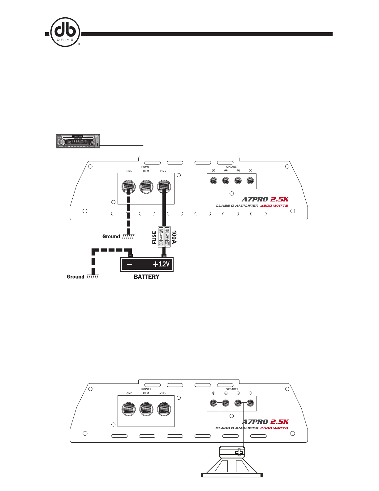
3-3. +12V, GND, REM CONNECTION.
12V ( POWER CONNECTION )
Before mounting amplifier, disconnect the negative ( - ) wire from battery to protect any accidential damage to
amplifier and audio system. A7PRO2.5K use minimum 4 gauge cables.
Connect the power cables to power terminal labeled as +12V. A7PRO2.5K is not equipped with fuses so you
need to install external fuses.
In order to install external fuses, connect one end of fuse holder to the power cable and the other end of
fuse holder to positive battery within 18in of the same cable gauge. This fuse location will protect the system
and the vehicle against the possibility of a short circuit in the power cable.
Be sure to use fuses and fuse holders adequate for the current draw application.
www.dbdrive.net
Page 4
WORLD RECORD BREAKING TECHNOLOGY
03
Remote turn on
CLASS D MONO AMPLIFIERS’ SPEAKER CONNECTION DIAGRAM 1.
8 ~ 1 ohms
GND ( GROUND CONNECTION )
Locate a secure grounding connection as close as possible. Make sure the location is clean and provides a direct
electrical connection to the frame of the vehicle.
Connect one end of a short piece of the same gauge cable as the power cable to the grounding point.
Run the one end of the cable to the grounding point. Run the other end of the cable to the mounting location.
Connect the ground cable to the screw terminal labeled as GND.
REM ( REMOTE CONNECTION )
Run a remote turn on cable from the headunit’s remote swithed +12V output.
3-4. SPEAKER CONNECTION
DB Drive recommends to use minimum 12 gauge speaker connecting cables. Run 12 gauge speaker
connecting cables from your speakers to amplifier’s mounting location.
Keep speaker cables away from the power cables and amplifier’s input cables. Use grommets anywhere
the cables have to pass through the holes in the metal frame or sheet metal. Connect to the speakers
according to the type of terminals on each speaker. Strip 3/8” of insulation from the end of each cable and
twist the cables strands together tightly. Make sure there are no stray strands that might touch other cables
or terminals and cause a short circuit.
Crimp spade lugs over the cable ends or tin the ends with solder to provide a secure termination.
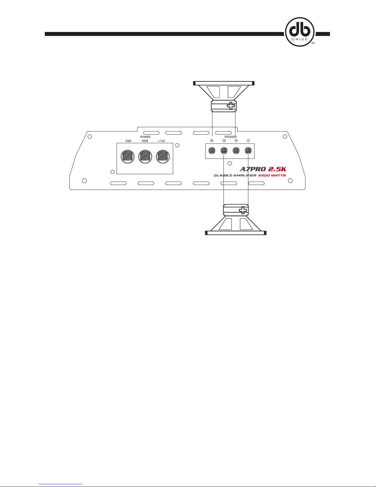
Connect the cable ends to amplifier as speaker system diagram.
AMPLIFIER +12V, GROUND, REMOTE CONNECTION DIAGRAM
Page 5
04
8 ~ 2 ohms
8 ~ 2 ohms
CLASS D MONO AMPLIFIERS’ SPEAKER CONNECTION DIAGRAM 2
www.dbdrive.net
4. TROUBLE SHOOTING
NO SOUND ( NO OUTPUT )
1) Please check all connections, cables’ routing, short and voltage at amplifier and headunit.
2) Please check built-in or external fuses, If it is brown, please repalce with new one.
3) Please check whether speakers work well, you can test speakers by connecting to another amplifiers.
PROTECTION
1) Please check overload, overheat ( thermal ) , short, voltage and DC offset.
2) Minimum working impedance for 1 ohm
3) If the amplifier is shut down due to overheat, Reset by turning off the remote input and allowing time to
cool down.
Please make sure there are no airflow obstructions around amplifier to prevent thermal protection.
WHINING NOISE
1) Engine noise is caused by poor grounding of amplifier, headunit, other components, battery or
alternator, so please check all grounding connections.
Page 6
P .
 Loading...