

d&b audiotechnik Z5409, Z5411 Mounting Instructions
Z
Z5409/11
Mounting instructions 1.1 en

d
u
c
t
General information
Z5409/11 Mounting instructions
Version: 1.1 en, / , D2960.EN .01
Copyright © by d&b audiotechnik GmbH; all rights reserved.
Keep these mountings instructions with the product or
in a safe place so that they are available for future
reference.
When reselling this product, hand over these mounting instructions
to the new owner.
d&b audiotechnik GmbH
Eugen-Adolff-Str. 134, D-71522 Backnang, Germany
T +49-7191-9669-0, F +49-7191-95 00 00
docadmin@dbaudio.com, www.dbaudio.com

1. Z5409/11 Horizontal bracket 10S/12S.................... 4
1.1. Scope of supply......................................................................... 4
1.2. Safety precautions..................................................................... 4
1.3. Intended use............................................................................... 5
1.4. Mounting options and angle settings....................................... 5
1.5. Assembly.................................................................................... 6
2. Fixing templates.................................................................. 8
3. Built-in dimensions........................................................... 10
4. Declarations....................................................................... 12
4.1.
Manufacturer's declaration..................................................... 12
4.2. Disposal................................................................................... 12
Contents
d&b Z5409/11 Mounting instructions 1.1 en 3
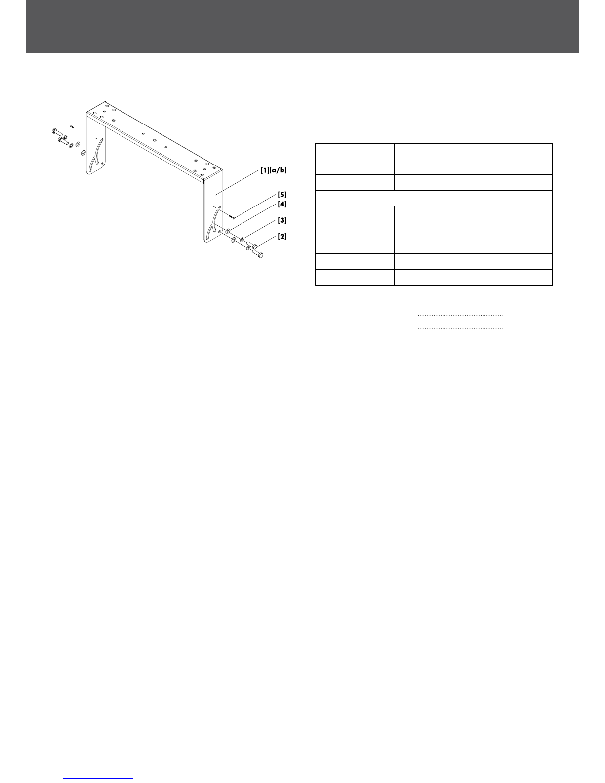
1.1. Scope of supply
Please verify the shipment for completeness and proper condition
of the items.
Qty. d&b Code Description
1 Z5409 d&b Horizontal bracket 10S [1a]
1 Z5411 d&b Horizontal bracket 12S [1b]
Each including:
4 Hex head bolt M10 x 25 [2]
4 Spring washer [3]
4 U washer [4]
2 Spax screw [5]
1 D2960 Mounting instructions
Technical information
Weight Horizontal bracket 10S 2.9 kg / 6.4 lb
Weight Horizontal bracket 12S 3.1 kg / 6.8 lb
1.2. Safety precautions
General safety
Installation and setup should only be carried out by qualified and
authorized personnel observing the valid national Rules for the
Prevention of Accidents (RPA).
It is the responsibility of the person installing the assembly to ensure
that the suspension/fixing points are suitable for the intended use.
Always carry out a visual and functional inspection of the items
before use. In case you have any doubt as to the proper
functioning and safety of the items, these must be withdrawn from
use immediately.
Load safety information
The maximum permitted working load of the Z5409 Horizontal
bracket 10S is 13 kg (29 lb) (according to BGV C1) which
corresponds to the weight of one 10S or 10S-D loudspeaker,
respectively.
The maximum permitted working load of the Z5411Horizontal
bracket 12S is 17 kg (37 lb) (according to BGV C1) which
corresponds to the weight of one 12S or 12S-D loudspeaker,
respectively.
Fig. 1: Scope of supply
1. Z5409/11 Horizontal bracket 10S/12S
d&b Z5409/11 Mounting instructions 1.1 en4
1.3. Intended use
The d&b Z5409/Z5411 Horizontal bracket 10S/12S must only
be used in conjunction with the d&b xS-Series loudspeakers 10S/
10S-D (Z5409) and 12S/12S-D (Z5411) as described in these
mounting instructions.
The bracket can be:
▪ directly mounted to walls.
▪ directly mounted to ceilings or other suitable surfaces.
▪ horizontally flown and mounted to bars and truss with a tube
diameter of up to 70 mm (2.75") using the Z5010 TV spigot
and the Z5012 Pipe clamp.
Note: Refer to the specific mounting instructions for assembly
and operation of these accessories.
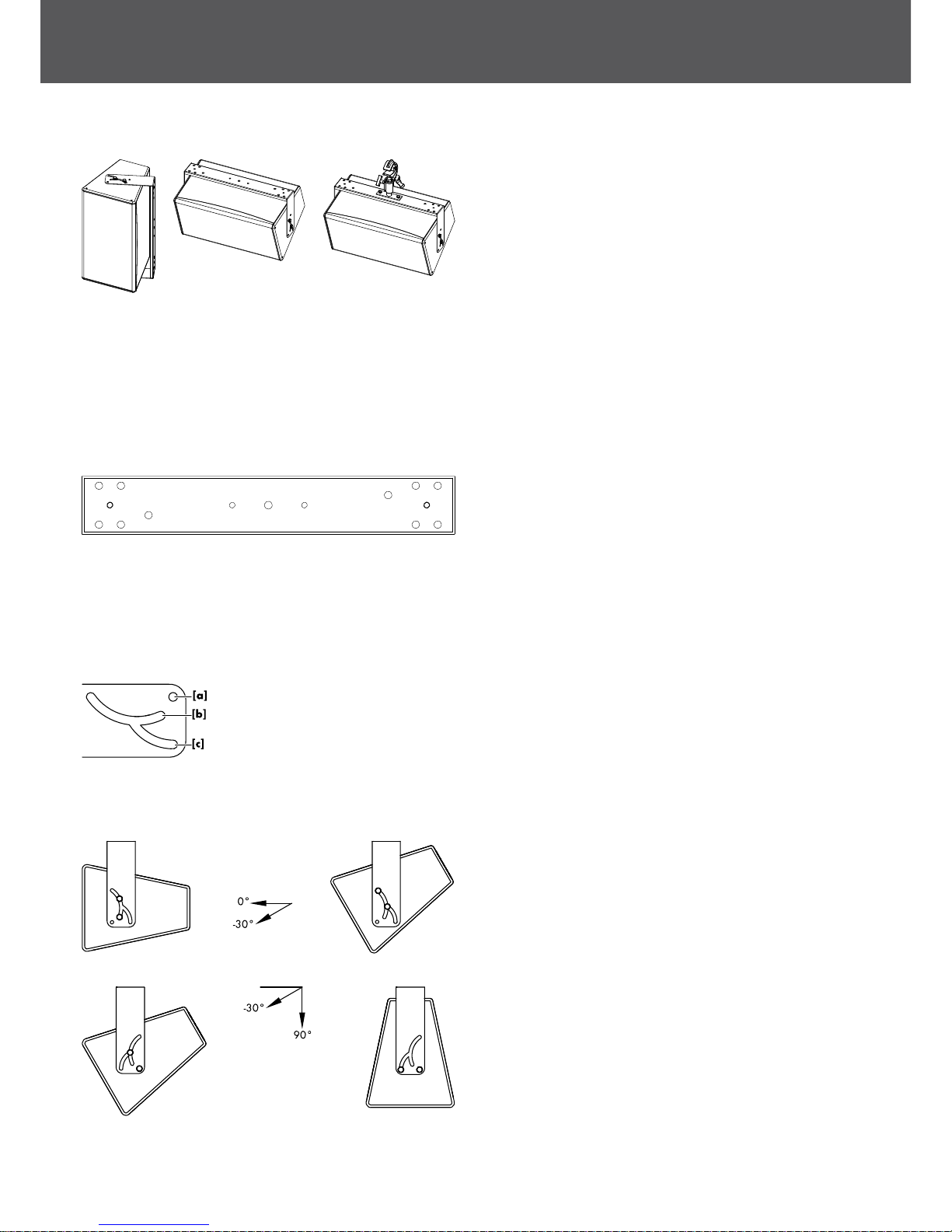
1.4. Mounting options and angle settings
Mounting holes are provided on the tie bar of the bracket.
One centered 9 mm (0.35") hole is provided at each end of the tie
bar for fixing the bracket directly to walls or ceilings or other
suitable surfaces.
Two centered 9 mm (0.35") holes at the d&b standard spacing of
115 mm (4.5") are provided to allow the attachment of the Z5010
TV spigot.
Five mounting holes are provided at each end of the tie bar to
attach the Z5044 MAX Bracket connector, the Z5053 Ci60/Ci90
Bracket connector or the Z5054 Ci60/Ci90 Flying adapter.
One 11 mm (0.43“) hole [a] and two semi-circular slots [b], [c]
are located at each end of the bracket.
Using the M10 threaded inserts at the top and bottom of the
loudspeaker cabinets, the bracket can be attached in two
directions to allow angle settings over a range of 105° starting
from +15° through to –90°. The following mounting options and
coverage angles are possible.
Option 1
The bracket is attached to the cabinet with hole [a] facing to the
front of the cabinet. Both bolts are fitted into slot [b].
The vertical coverage angle can be set over a range of 30°
starting from 0° to –30°.
Option 2
The bracket is attached to the cabinet with hole [a] facing to the
back of the cabinet. One bolt is fitted into hole [a] and the second
one is fitted into the axis of slot [b] and slot [c] to allow the bolt to
move in slot [c].
The vertical coverage angle can be set over a range of 60°
starting from –30° to –90°.
Fig. 2: Z5409/Z5411 Rigging examples
Fig. 3: Z5409/Z5411 Mounting holes
d&b Z5409/11 Mounting instructions 1.1 en 5
 Loading...