

d&b audiotechnik Z Series, Z5404 Flying bracket 8S, Z5405 Flying bracket 10S, Z5406 Flying bracket 12S Mounting Instructions
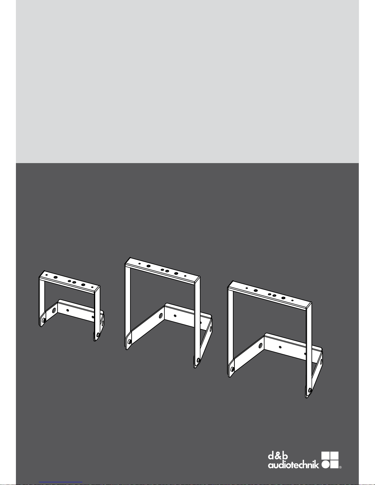
Z
Z5404/05/06
Mounting instructions 1.1 en

d
u
c
t
General information
Z5404/05/06 Mounting instructions
Version: 1.1 en, 02/2013, D2958.EN .01
Copyright © 2013 by d&b audiotechnik GmbH; all rights
reserved.
Keep these mountings instructions with the product or
in a safe place so that they are available for future
reference.
When reselling this product, hand over these mounting instructions
to the new owner.
d&b audiotechnik GmbH
Eugen-Adolff-Str. 134, D-71522 Backnang, Germany
T +49-7191-9669-0, F +49-7191-95 00 00
docadmin@dbaudio.com, www.dbaudio.com

1. Z5404/05/06 Flying bracket 8S/10S/12S............... 4
1.1. Scope of supply......................................................................... 4
1.2. Safety precautions..................................................................... 4
1.3. Intended use............................................................................... 5
1.4. Mounting options and angle settings....................................... 5
1.5. Assembly.................................................................................... 5
2. Fixing templates.................................................................. 7
3. Built-in dimensions........................................................... 10
4. Declarations....................................................................... 12
4.1.
Manufacturer's declaration..................................................... 12
4.2. Disposal................................................................................... 12
Contents
d&b Z5404/05/06 Mounting instructions 1.1 en 3
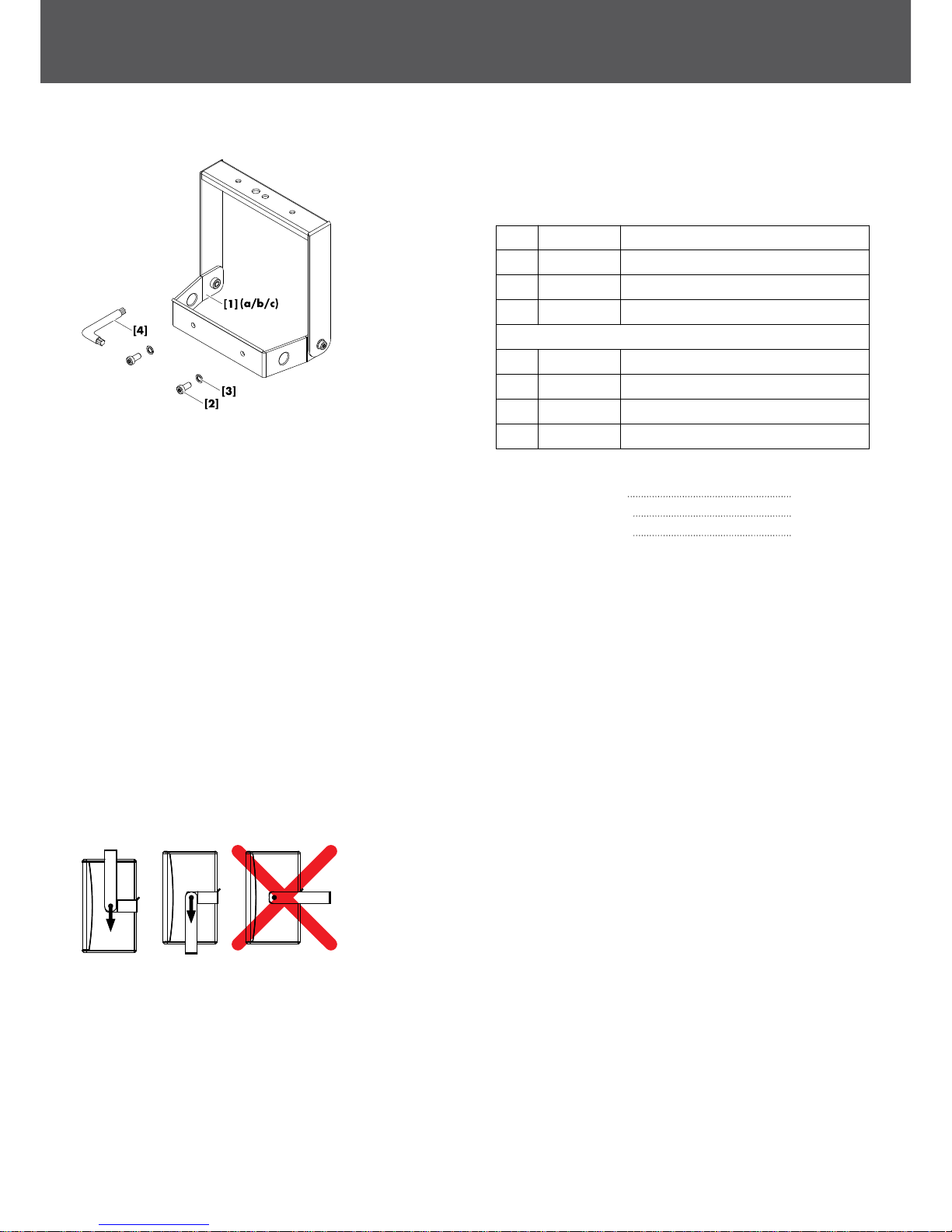
1.1. Scope of supply
Please verify the shipment for completeness and proper condition
of the items.
Qty. d&b Code Description
1 Z5404 d&b Flying bracket 8S [1a]
1 Z5405 d&b Flying bracket 10S [1b]
1 Z5406 d&b Flying bracket 12S [1c]
Each including:
2 Pan head screw (Torx #T45) M8 x 20 [2]
2 Spring washer [3]
1 Torx key [4] (size #T45)
1 D2958 Mounting instructions
Technical information
Weight Flying bracket 8S 1.6 kg / 3.5 lb
Weight Flying bracket 10S 2.8 kg / 6.2 lb
Weight Flying bracket 12S 2.9 kg / 6.4 lb
1.2. Safety precautions
General safety
Installation and setup should only be carried out by qualified and
authorized personnel observing the valid national Rules for the
Prevention of Accidents (RPA).
It is the responsibility of the person installing the assembly to ensure
that the suspension/fixing points are suitable for the intended use.
Always carry out a visual and functional inspection of the items
before use. In case you have any doubt as to the proper
functioning and safety of the items, these must be withdrawn from
use immediately.
Load safety information
Always align the bracket vertically when using it, whether it is
suspended or placed on top of a loudspeaker stand.
The maximum permitted working load of the Z5404 Flying bracket
8S is 7.4 kg (16 lb) (according to BGV C1) which corresponds to
the weight of one 8S loudspeaker.
The maximum permitted working load of the Z5405 Flying bracket
10S is 13 kg (29 lb) (according to BGV C1) which corresponds to
the weight of one 10S or 10S-D loudspeaker, respectively.
The maximum permitted working load of the Z5406 Flying bracket
12S is 17 kg (37 lb) (according to BGV C1) which corresponds to
the weight of one 12S or 12S-D loudspeaker, respectively.
Fig. 1: Scope of supply
1. Z5404/05/06 Flying bracket 8S/10S/12S
d&b Z5404/05/06 Mounting instructions 1.1 en4

1.3. Intended use
The d&b Z5404/05/06 Flying bracket 8S/10S/12S must only be
used in conjunction with the d&b xS-Series loudspeakers 8S, 10S/
10S-D and 12S/12S-D as described in these mounting instructions.
The bracket can be:
▪ directly mounted to ceilings.
▪ vertically flown and mounted to bars and truss with a tube
diameter of up to 70 mm (2.75") using the Z5010 TV spigot
and the Z5012 Pipe clamp.
Note: Refer to the specific mounting instructions for assembly
and operation of these accessories.
1.4. Mounting options and angle settings
Mounting holes are provided on the tie bar of the bracket.
Two 6.5 mm (0.25") holes are provided onn the tie bar for fixing
the bracket directly the ceiling.
Two M8 threaded inserts at the d&b standard spacing of 115 mm
(4.5") are provided to allow the attachment of the Z5010 TV
spigot.
Vertical angles can continuously be set in the range of 90°.
1.5. Assembly
Fixing the bracket to the ceiling
NOTICE!
Only use mounting parts (fixing anchors and screws) that are
suitable for the intended application.
Observe the occurring extraction forces acting on the fixing
anchors and screws. The rated extraction forces for the respective
cabinet are listed in the following table.
Application Rated extraction forces
8S 10S 12S
Ceiling mounting 100 N 250 N 300 N
To attach the bracket to the ceiling, use the holes shown in the
graphic opposite to provide adequate support.
A corresponding fixing template is supplied with these mounting
instructions. Refer to Þ Chapter 2. "Fixing templates"
on page 7.
Fig. 2: Z5404/05/06 Rigging examples
Fig. 3: Z5404/05/06 Mounting holes
d&b Z5404/05/06 Mounting instructions 1.1 en 5
 Loading...