

d&b audiotechnik Z5402, Z54003 Mounting Instructions
Z
Z5402/03
Mounting instructions 1.1 en

d
u
c
t
General information
Z5402/03 Mounting instructions
Version: 1.1 en, / , D2957.EN .01
Copyright © by d&b audiotechnik GmbH; all rights reserved.
Keep these mountings instructions with the product or
in a safe place so that they are available for future
reference.
When reselling this product, hand over these mounting instructions
to the new owner.
d&b audiotechnik GmbH
Eugen-Adolff-Str. 134, D-71522 Backnang, Germany
T +49-7191-9669-0, F +49-7191-95 00 00
docadmin@dbaudio.com, www.dbaudio.com

1. Z5402/Z5403 Wall mount M/L..................................... 4
1.1. Scope of supply......................................................................... 4
1.2. Safety precautions..................................................................... 4
1.3. Intended use............................................................................... 5
1.4. Mounting options....................................................................... 5
1.5. Assembly.................................................................................... 5
1.6. Vertical and horizontal alignment............................................. 6
2. Fixing templates.................................................................. 8
2.1.
Vertical setup.............................................................................. 8
2.2. Horizontal setup......................................................................... 9
3. Built-in dimensions........................................................... 10
3.1.
Wall mount M/L ..................................................................... 10
3.2. 8S loudspeaker....................................................................... 11
3.3. 10S/10S-D loudspeaker........................................................ 13
3.4. 12S/12S-D loudspeaker........................................................ 15
4. Declarations....................................................................... 17
4.1.
Manufacturer's declaration..................................................... 17
4.2. Disposal................................................................................... 17
Contents
d&b Z5402/03 Mounting instructions 1.1 en 3
1.1. Scope of supply
Please verify the shipment for completeness and proper condition
of the items.
Qty. d&b Code Description
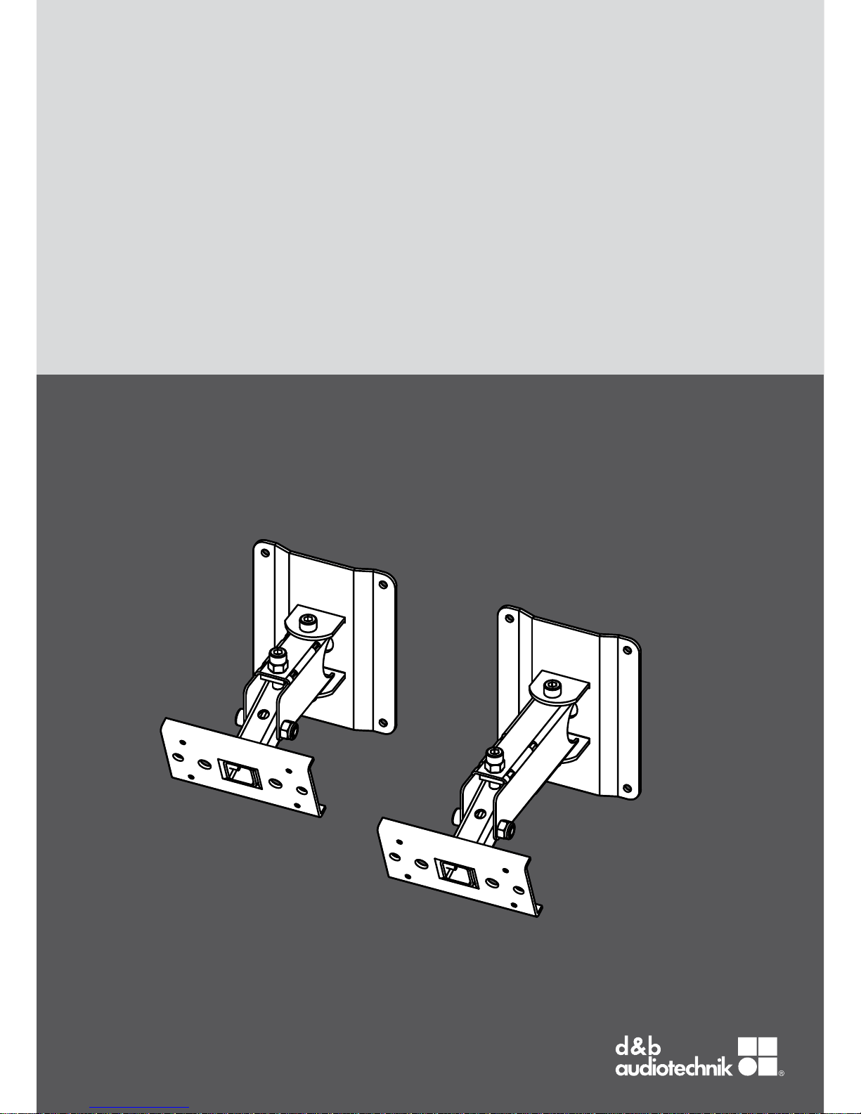
1 Z5402 d&b Wall mount M [1] (a)
1 Z5403 d&bWall mount L [1] (b)
Each including:
2 Hex head bolt M8 x 20 [2]
2 Spring washer [3]
1 D2957 Mounting instructions
Technical information
Weight Wall mount M 1.3 kg / 2.9 lb
Weight Wall mount L 1.4 kg / 3.1 lb
1.2. Safety precautions
General safety
Installation and setup should only be carried out by qualified and
authorized personnel observing the valid national Rules for the
Prevention of Accidents (RPA).
It is the responsibility of the person installing the assembly to ensure
that the suspension/fixing points are suitable for the intended use.
Always carry out a visual and functional inspection of the items
before use. In case you have any doubt as to the proper
functioning and safety of the items, these must be withdrawn from
use immediately.
Load safety information
The maximum permitted working load of the Z5402 Wall mount M
and Z5403 Wall mount L is 17 kg (37 lb) (according to BGV C1)
which implies the weight of one 8S/10S/10S-D/12S or 12S-D
cabinet.
Fig. 1: Scope of supply
1. Z5402/Z5403 Wall mount M/L
d&b Z5402/03 Mounting instructions 1.1 en4
1.3. Intended use
The d&b Z5402 Wall mount M and Z5403 Wall mount L must
only be used in conjunction with the d&b xS-Series loudspeakers
8S, 10S/10S-D and 12S/12S-D as described in these mounting
instructions.
The wall mounts allow both horizontal or vertical mounting of the
cabinets as well as vertical and horizontal alignment.
1.4. Mounting options
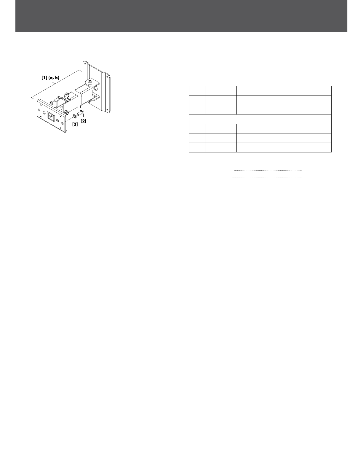
Mounting options
The tilt unit [6] of the wall mount can be rotated through 90°
allowing the cabinet to be mounted either vertically (a) or
horizontally (b).
To change the orientation of the tilt unit, proceed as follows:
Tools required:
▪ Open-ended spanner/wrench (size #13)
▪ Allen hex key (6 mm)
1. Slacken and undo the self-securing nut [1] and remove the
fixing bolt [2].
2. Remove the tilt unit [3] and turn it through 90°.
3. Refit the tilt unit in reverse order.
1.5. Assembly
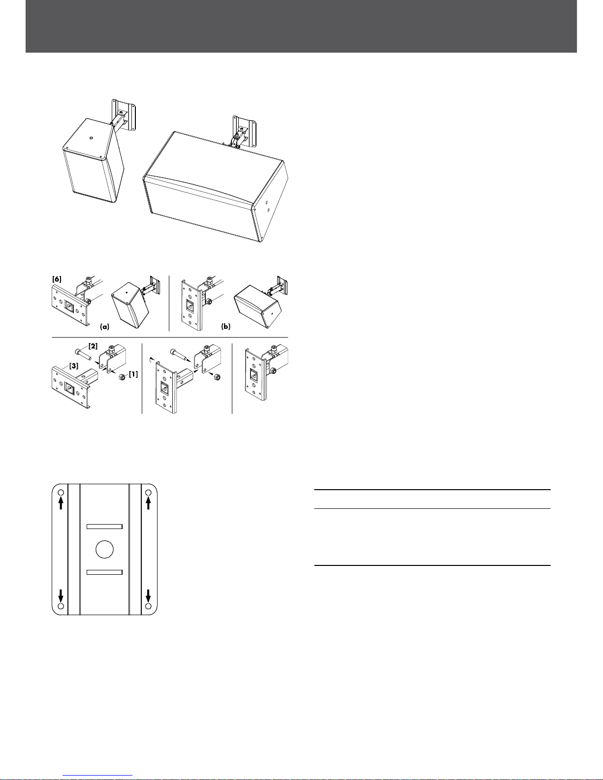
Mounting plate
NOTICE!
Only use mounting parts (fixing anchors and screws) that are
suitable for the intended application.
Observe the occurring extraction forces acting on the fixing
anchors and screws. The rated extraction force is 350 N.
A corresponding fixing template is supplied with these mounting
instructions. Refer to Þ Chapter 2. "Fixing templates"
on page 8.
An additional 20 mm (0.8") centered hole is provided on the
mounting plate as a feed-through for the connection cable. The
cable can be fed through the mounting plate into the boom arm
that acts as a cable run.
d&b Z5402/03 Mounting instructions 1.1 en 5
Attaching the cabinet to the wall mount
NOTICE!
▪ Only use the supplied and specified screws [2], otherwise there
a risk of damaging the threaded inserts.
▪ Always use the supplied spring washers [3] to prevent the bolts
from slackening.
Tools required:
▪ Open-ended spanner/wrench (size #13)
1. Attach the wall mount to the two M8 threaded inserts on the
rear panel of the cabinet.
2. Insert the screws together with the spring washers and tighten
them.
1.6. Vertical and horizontal alignment
The wall mounts allow both vertical and horizontal alignment of the
cabinets. The possible vertical and horizontal angle settings
depend on the cabinet size, the deployment of the cabinets
(vertical or horizontal setup) and the type of wall mount used. The
various options and angle settings including the built-in dimensions
are detailed in Þ Chapter 2. "Fixing templates" on page 8.
Tools required:
▪ Open-ended spanner/wrench (size #13)
▪ Allen hex key (6 mm).
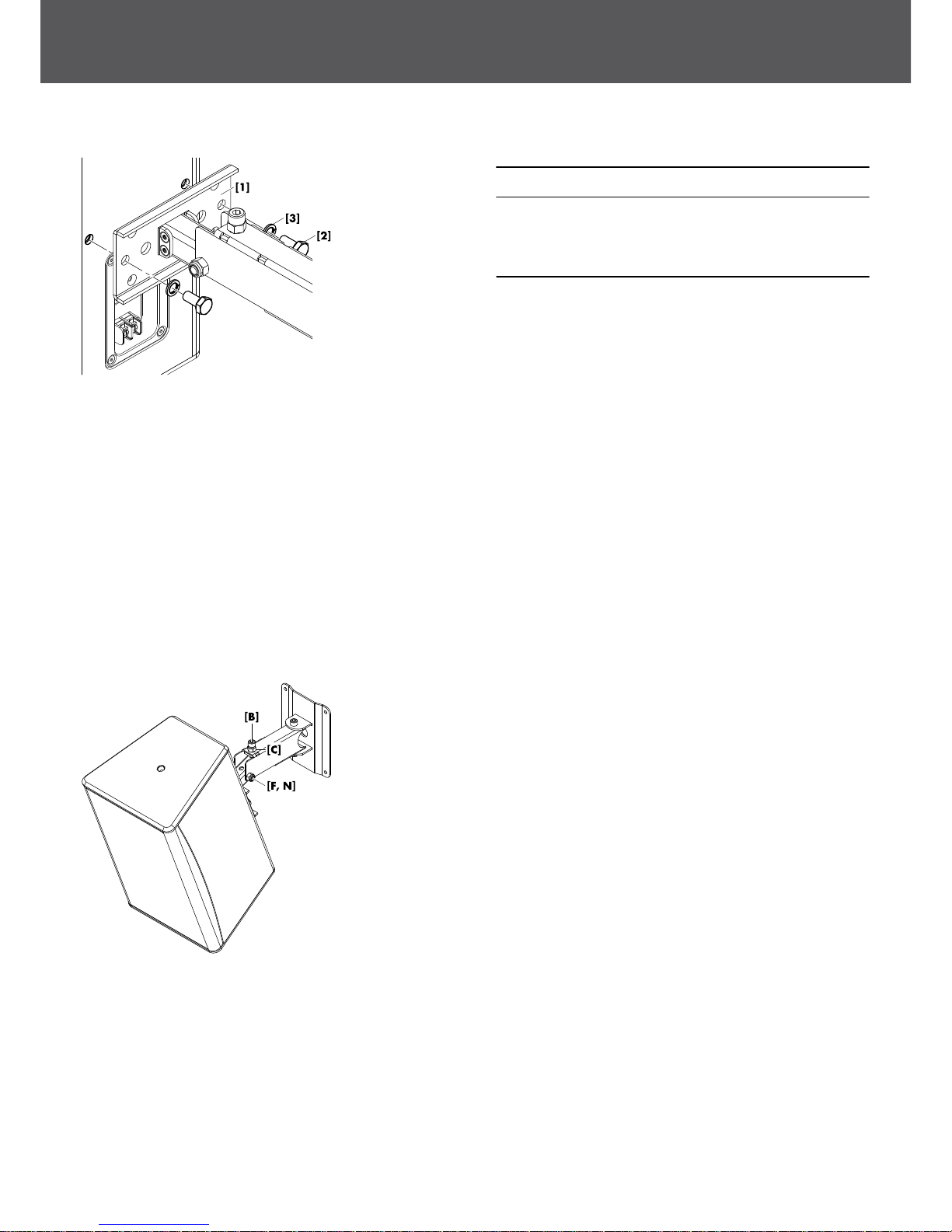
Vertical alignment
The wall mounts are equipped with a stop screw [B] to allow a
precise vertical alignment of the cabinet.
1. Slacken the stop screw [B].
2. Slightly slacken the fixing bolt [F].
3. Set the cabinet to the desired vertical angle.
4. Adjust the stop screw [B] until the desired angle is finally set.
5. Tighten the counter nut [C] to fix the adjustment.
6. Retighten the fixing bolt.
d&b Z5402/03 Mounting instructions 1.1 en6
 Loading...