

V
Vi7P/Vi10P
Manual 1.1 en

d
u
c
t
General information
Vi7P/Vi10P Manual
Version: 1.1 en, 08/2015, D2724.EN .01
Copyright © 2015 by d&b audiotechnik GmbH; all rights
reserved.
Keep this manual with the product or in a safe place
so that it is available for future reference.
When reselling this product, hand over this manual to the new
owner.
If you supply d&b products, please draw the attention of your
customers to this manual. Enclose the relevant manuals with the
systems. If you require additional manuals for this purpose, you
can order them from d&b.
d&b audiotechnik GmbH
Eugen-Adolff-Strasse 134, D-71522 Backnang, Germany
T +49-7191-9669-0, F +49-7191-95 00 00
docadmin@dbaudio.com, www.dbaudio.com

1. Safety precautions........................................................... 4
1.1. Information regarding the use of loudspeakers.................... 4
2. Vi7P/Vi10P loudspeaker.............................................. 5
2.1. Product description.................................................................. 5
2.2. Connections............................................................................. 5
2.3. Operation................................................................................ 7
2.3.1. Controller settings................................................................ 7
2.4. Dispersion characteristics........................................................ 9
2.5. Technical specifications........................................................ 12
3. Manufacturer's declarations..................................... 14
3.1.
EU conformity of loudspeakers (CE symbol)....................... 14
3.1.1. WEEE Declaration (Disposal)........................................... 14
Contents
d&b Vi7P/Vi10P Manual 1.1 en 3

1.1. Information regarding the use of loudspeakers
Potential risk of personal injury
Never stand in the immediate vicinity of loudspeakers driven at a
high level. Professional loudspeaker systems are capable of
causing a sound pressure level detrimental to human health.
Seemingly non-critical sound levels (from approx. 95 dB SPL) can
cause hearing damage if people are exposed to it over a long
period.
In order to prevent accidents when deploying loudspeakers on the
ground or when flown, please take note of the following:
– When setting up the loudspeakers or loudspeaker stands,
make sure they are standing on a firm surface. If you place
several systems on top of one another, use straps to secure
them against movement.
– Only use accessories which have been tested and approved
by d&b for assembly and mobile deployment. Pay attention to
the correct application and maximum load capacity of the
accessories as detailed in our specific "Mounting instructions"
or in our "Flying system and Rigging manuals".
– Ensure that all additional hardware, fixings and fasteners used
for installation or mobile deployment are of an appropriate
size and load safety factor. Pay attention to the manufacturers'
instructions and to the relevant safety guidelines.
– Regularly check the loudspeaker housings and accessories for
visible signs of wear and tear, and replace them when
necessary.
– Regularly check all load bearing bolts in the mounting devices.
Potential risk of material damage
Loudspeakers produce a static magnetic field even if they are not
connected or are not in use. Therefore make sure when erecting
and transporting loudspeakers that they are nowhere near
equipment and objects which may be impaired or damaged by an
external magnetic field. Generally speaking, a distance of 0.5 m
(1.5 ft) from magnetic data carriers (floppy disks, audio and video
tapes, bank cards, etc.) is sufficient; a distance of more than 1 m
(3 ft) may be necessary with computer and video monitors.
1. Safety precautions
d&b Vi7P/Vi10P Manual 1.1 en4
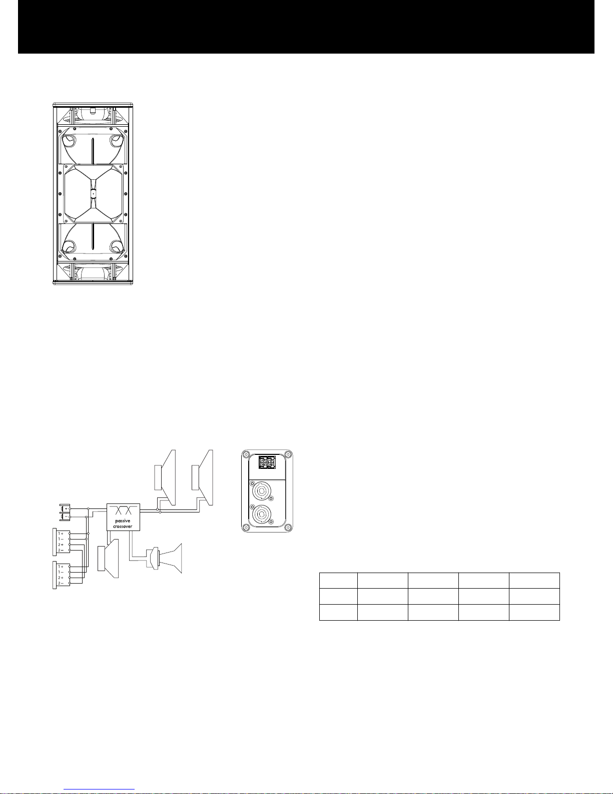
2.1. Product description
Vi7P/Vi10P are passive 3-way loudspeakers housing two 10" LF
drivers, one horn-loaded 8" MF driver and a 1.4" HF compression
driver with a rotatable CD horn producing a nominal dispersion (h
x v) of 75° x 40° (Vi7P) or 110° x 40° (Vi10P), respectively.
All components are arranged symmetrically around the center axis
of the cabinet to produce a perfect symmetrical dispersion pattern.
This setup allows for a crossover design with a well defined
overlap of adjacent frequency bands resulting in a very consistent
and accurate vertical dispersion. Due to the dipolar arrangement
of the low drivers, broadband vertical dispersion control is
maintained down to approximately 350 Hz – an outstanding
feature for a passive 3-way system.
The frequency response extends from 59 Hz to above 18 kHz.
The cabinets are constructed from marine plywood and have an
impact and weather protected PCP (Polyurea Cabinet Protection)
finish. The fronts of the loudspeaker cabinets are protected by a
rigid metal grill backed by an acoustically transparent foam.
The cabinets are fitted with two M10 threaded inserts each on the
top, bottom and rear panels to accept either:
– the Z5383 VP Mounting bracket,
– the Z5384 VP Flying adapter,
– or the Z5384 VP Flying adapter.
In addition the Q9032 Safety eye bolt M10 can be used to apply
an independent secondary safety device.
2.2. Connections
The cabinets are fitted with a pair of NL4 M connectors and a two
pole screw terminal block (ST). All four pins of both NL4 M
connectors are wired in parallel. The cabinets use the pin
assignments 1+/1–. Pins 2+/2– are designated to active
subwoofers.
Cabinets with the weather resistant option (WR) are equipped with
a fixed input cable (PG type, H07-RN-F, 2 x 2.5 mm2 (AWG 13),
standard length 5.5 m (18 ft).
Pin equivalents of the applicable connector options are listed in the
table below.
NL4 M
1+ 1– 2+ 2–
ST + – n.a. n.a.
PG Brown (+) Blue (–) n.a. n.a.
2. Vi7P/Vi10P loudspeaker
d&b Vi7P/Vi10P Manual 1.1 en 5

Fixed cable connection
The Vi7P and Vi10P loudspeakers are each supplied with a cover
plate [1] and a rubber grommet feed through [2]. For indoor
operation, these items can be used to hide the connector panel, if
required. For unprotected outdoor operation, the connector panel
must be covered, i.e. both items must be used to achieve an IP
degree of protection of IP34.
To install the fixed cable connection, proceed as follows:
Tools required: Philips screw driver (#PH2).
1. Remove the knockout opening in the cover plate [1] and
attach the rubber grommet [2] correspondingly.
2. Insert the connection cable through the rubber grommet.
3. Undo the four screws of the connector panel.
4. Connect the cable wires to the screw terminal.
Þ Observe the correct polarity!
5. Push the cover plate towards the connector panel until it fits
into place.
6. Finally fix the cover plate together with the connector panel
using all screws.
Step 2 Step 3 Step 4/5 Step 6
Installing the fixed cable connection
Cover plate and rubber grommet
Step 1
d&b Vi7P/Vi10P Manual 1.1 en6

NL4 connection with cover plate
The two NL4 connector sockets of the cabinet's connector panel
are located in a recess to allow the use of the cover plate [1]
together with NL4 cable connectors, as shown in the graphic
opposite.
Note: Neutrik NL4FC type connectors must be used for this
option.
The cover plate is equipped with two knockout openings to allow
daisy chaining of the loudspeaker.
To use the NL4 connection, proceed in the same manner as
described in the previous section.
2.3. Operation
NOTICE!
Only operate d&b loudspeakers with a correctly configured d&b
amplifier, otherwise there is a risk of damaging the loudspeaker
components.
Application Setup Cabinets per
channel
Vi7P V7P 2
Vi10P V10P 2
For applicable d&b amplifiers, the controller setups are available
in Dual Channel and/or Mix TOP/SUB mode. For combinations
with active subwoofers fed by a single 4-wire cable Mix TOP/SUB
mode must be selected.
2.3.1. Controller settings
For acoustic adjustment the functions CUT, HFA and CPL can be
selected.
CUT circuit
Set to CUT, the cabinet low frequency level is reduced. The
cabinets are now configured for use with actively driven d&b
subwoofers.
NL4 cable connection with cover plate [1]
d&b Vi7P/Vi10P Manual 1.1 en 7

HFA circuit
In HFA mode (High Frequency Attenuation), the HF response of the
system is rolled off. HFA provides a natural, balanced frequency
response when a unit is placed close to listeners in near field or
delay use.
High Frequency Attenuation begins gradually at 1 kHz, dropping
by approximately 3 dB at 10 kHz. This roll off mimics the decline
in frequency response experienced when listening to a system from
a distance in a typically reverberant room or auditorium.
CPL circuit
The CPL (Coupling) circuit compensates for coupling effects
between the cabinet and close boundary surfaces. CPL begins
gradually around 1 kHz, with the maximum attenuation below
400 Hz. To achieve a balanced frequency response, the CPL
circuit can be set to dB attenuation values between 0 and –9.
Positive CPL values create an adjustable low frequency boost (0 to
+5 dB) at around 65 Hz and can be set when the system is used in
full range mode without subwoofers.
-5
0
5
10
-10
-15
-20
-25
-30
20
100 1k 10k
20k
Frequency response correction of HFA circuit
Frequency response correction of CPL circuit
d&b Vi7P/Vi10P Manual 1.1 en8

2.4. Dispersion characteristics
The following graphs show dispersion angle over frequency of a
single cabinet plotted using lines of equal sound pressure (isobars)
at –6 dB and –12 dB.
Isobar diagram horizontal
Vi7P
vertical setup
Isobar diagram vertical
Isobar diagram horizontal
Vi7P
horizontal setup,
horn rotated
Isobar diagram vertical
d&b Vi7P/Vi10P Manual 1.1 en 9

Isobar diagram horizontal
Vi10P
vertical setup
Isobar diagram vertical
Isobar diagram horizontal
Vi10P
horizontal setup,
horn rotated
Isobar diagram vertical
d&b Vi7P/Vi10P Manual 1.1 en10

Altering the HF horn dispersion
By factory default, the HF horn is fitted to the cabinet providing the
nominal horizontal dispersion when the cabinet is used in upright
position. This is indicated by a white label on the horn flange. The
label is visible through the front grill on each side of the cabinet as
shown in the graphic opposite.
The HF horn can be rotated through 90°.
Tools required: Torx wrench (#TX20).
1. Undo the torx screws on the top and bottom panels of the
cabinet and remove the front grill.
2. Undo the screws holding the horn flange and rotate the horn.
3. Refit the horn as follows:
– Make sure the gasket of the horn is in place.
– Refit the horn.
– Insert all screws and carefully tighten them clockwise until
they fit precisely into the countersunk holes.
4. Refit the front grill.
Altering the HF dispersion
d&b Vi7P/Vi10P Manual 1.1 en 11

2.5. Technical specifications
Vi7P/Vi10P system data
Frequency response (–5 dB standard) 59 Hz - 18 kHz
Frequency response (–5 dB CUT mode) 100 Hz - 18 kHz
Max. sound pressure (1 m, free field)
Vi7P with D12/D20/30D 139 dB
Vi7P with D80 142 dB
Vi10P with D12/D20/30D 138 dB
Vi10P with D80 141 dB
(SPLmax peak, pink noise test signal with crest factor of 4)
Input level (100 dB
SPL
/1 m)
–17 dBu
Vi7P/Vi10P loudspeaker
Nominal impedance
8 ohms
Power handling capacity (RMS/peak 10 ms) 500/2000 W
Nominal dispersion angle (horizontal) Vi7P 75°
Nominal dispersion angle (horizontal) Vi10P 110°
Nominal dispersion angle (vertical) 40°
Components 2 x 10" LF driver with neodymium magnet
1 x 8" MF driver with neodymium magnet
1.4” exit compression driver
Passive crossover network
Connections 2 x NL4 M
1 x screw terminal (ST - up to 4 mm2/AWG 11)
Optional fixed cable (PG):
H07-RN-F, 2 x 2.5 mm2 (AWG 13), 5.5 m (18 ft)
Pin assignment NL4 M: 1+/1–
Fixed cable (PG): Brown: (+) / Blue: (–)
Weight 33 kg (75 lb)
Vi7P frequency response, standard and CUT modes
Vi10P frequency response, standard and CUT modes
d&b Vi7P/Vi10P Manual 1.1 en12

Vi7P/Vi10P cabinet dimensions in mm [inch]
d&b Vi7P/Vi10P Manual 1.1 en 13

3.1. EU conformity of loudspeakers (CE symbol)
This declaration applies to:
d&b Vi7P loudspeaker, Z0724
d&b Vi10P loudspeaker, Z0725
manufactured by d&b audiotechnik GmbH.
All production versions of these types are included, provided they
correspond to the original technical version and have not been
subject to any later design or electromechanical modifications.
We herewith declare that said products are in conformity with the
provisions of the respective EC directives including all applicable
amendments.
A detailed declaration is available on request and can be ordered
from d&b or downloaded from the d&b website at
www.dbaudio.com.
3.1.1. WEEE Declaration (Disposal)
Electrical and electronic equipment must be disposed of separately
from normal waste at the end of its operational lifetime.
Please dispose of this product according to the respective national
regulations or contractual agreements. If there are any further
questions concerning the disposal of this product, please contact
d&b audiotechnik.
3. Manufacturer's declarations
d&b Vi7P/Vi10P Manual 1.1 en14


D2724.EN .01, 08/2015 © d&b audiotechnik GmbH
www.dbaudio.com
 Loading...