

d&b audiotechnik Ti10 User Manual
Ti10
T
Manual 1.2 en

General information
Ti10 Manual
Version: 1.2 en, 10/2018, D2602.EN .01
Copyright © 2018 by d&b audiotechnik GmbH; all rights
reserved.
Keep this document with the product or in a safe place
so that it is available for future reference.
We recommend you to regularly check the d&b website for the
latest version of this document.
When reselling this product, hand over this document to the new
owner.
If you supply d&b products, please draw the attention of your
customers to this document. Enclose the relevant documents with
the systems. If you require additional documents for this purpose,
you can order them from d&b.
d&b audiotechnik GmbH
Eugen-Adolff-Straße 134, D-71522 Backnang, Germany
T +49-7191-9669-0, F +49-7191-95 00 00

Contents
1 Safety precautions.............................................................. 4
1.1 Information regarding the use of loudspeakers........................ 4
2 Ti10 loudspeaker................................................................. 5
2.1 Product description..................................................................... 5
2.2 Connections................................................................................ 6
2.3 Operation.................................................................................... 6
2.3.1 Controller settings.................................................................... 7
2.4 Dispersion characteristics........................................................... 8
2.5 Technical specifications.............................................................. 9
3 Ti10L Rigging procedure................................................ 11
4 Manufacturer's declarations......................................... 12
4.1 EU conformity of loudspeakers (CE symbol).......................... 12
4.1.1 WEEE Declaration (Disposal).............................................. 12
d&b Ti10 Manual 1.2 en 3

1 Safety precautions
1.1 Information regarding the use of loudspeakers
Potential risk of personal injury
Never stand in the immediate vicinity of loudspeakers driven at a
high level. Professional loudspeaker systems are capable of
causing a sound pressure level detrimental to human health.
Seemingly non-critical sound levels (from approx. 95 dB SPL) can
cause hearing damage if people are exposed to it over a long
period.
In order to prevent accidents when deploying loudspeakers on the
ground or when flown, please take note of the following:
▪ When setting up the loudspeakers or loudspeaker stands, make
sure they are standing on a firm surface. If you place several
systems on top of one another, use straps to secure them
against movement.
▪ Only use accessories which have been tested and approved by
d&b for assembly and mobile deployment. Pay attention to the
correct application and maximum load capacity of the
accessories as detailed in our specific "Mounting instructions" or
in our "Flying system and Rigging manuals".
▪ Ensure that all additional hardware, fixings and fasteners used
for installation or mobile deployment are of an appropriate size
and load safety factor. Pay attention to the manufacturers'
instructions and to the relevant safety guidelines.
▪ Regularly check the loudspeaker housings and accessories for
visible signs of wear and tear, and replace them when
necessary.
▪ Regularly check all load bearing bolts in the mounting devices.
Potential risk of material damage
Loudspeakers produce a static magnetic field even if they are not
connected or are not in use. Therefore make sure when erecting
and transporting loudspeakers that they are nowhere near
equipment and objects which may be impaired or damaged by an
external magnetic field. Generally speaking, a distance of 0.5 m
(1.5 ft) from magnetic data carriers (floppy disks, audio and video
tapes, bank cards, etc.) is sufficient; a distance of more than 1 m
(3 ft) may be necessary with computer and video monitors.
d&b Ti10 Manual 1.2 en4
2 Ti10 loudspeaker
2.1 Product description
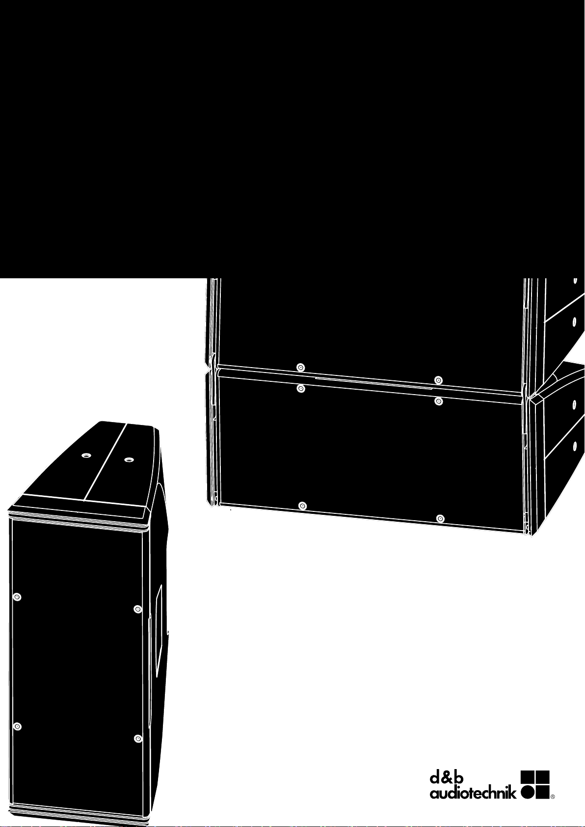
The Ti10 is a very compact loudspeaker system which can be used
both, as a line array and as a high directivity point source speaker.
For these applications, the Ti10 cabinet provides two different
dispersion characteristics which can be swapped over without any
tools.
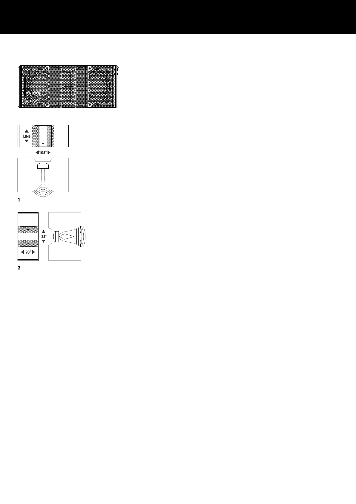
The core of the design is a unique combination of a rotatable
waveguide with horn and an acoustic lens. The horn natively
provides a vertical line source with 90° horizontal dispersion. The
lens is part of the front grill and widens the HF dispersion in line
array mode to 105° (Ti10L).
When used upright as a point source, the lens curves the wavefront
of the line source providing a 90° x 35° dispersion pattern
(Ti10P).
The Ti10 is a two way design, employing dual 6.5” drivers, a 1.4”
exit compression driver and a passive crossover network. The low
drivers are positioned in a dipolar arrangement providing an
exceptional dispersion control towards low frequencies.
Its frequency response extends from 68 Hz to above 18 kHz.
Ti10 Loudspeaker
1: Horn and lens in line source setup Ti10L
2: Horn and lens in point source setup Ti10P
The cabinet is constructed from polyurethane integral hard foam
with an impact and weather resistant black paint finish. The cabinet
shape allows the system to be set up as a single unit in upright
orientation or as a line array in user defined vertical configurations.
The front of the loudspeaker cabinet is protected by a rigid metal
grill in front of an acoustically transparent foam.
Ti-Series rigging components and arrays
For line and point source applications the Ti10 loudspeaker is
available in two different cabinet versions which are acoustically
identical:
▪ Ti10L: Line source version including line array rigging devices.
It can be used as a line array and as a stand-alone loudspeaker
with both horn orientations.
▪ Ti10P: Point source version without line array rigging devices. It
can be used as a stand-alone loudspeaker with both horn
orientations.
For line array applications Ti10L cabinets are mechanically
connected using the rigging strands on both sides of the cabinet
front and a central strand at the rear of the cabinet. All necessary
rigging components are mounted to the cabinet and are folded or
slide out when needed. Splay angles between adjacent cabinets
can be set in the range from 0° to 15°. Please also refer to
Þ Chapter 3 "Ti10L Rigging procedure" on page 11.
For point source applications, the Ti10P is fitted with six threaded
inserts to connect to different rigging accessories such as
Z5371 T Flying bracket, Z5372 T Horizontal bracket,
Z5354 E8/E12 Flying adapter or Z5020 Flying adapter 02/
Z5025 Flying adapter 03.
d&b Ti10 Manual 1.2 en 5
 Loading...