

d&b audiotechnik R70 User Manual

R70
Ethernet to CAN interface
Manual (1.4 EN)

General information
R70 Ethernet to CAN interface
Manual
Version 1.4 EN, 04/2009, D2402.EN .01
Copyright © 2009 by d&b audiotechnik GmbH; all rights reserved.
d&b audiotechnik GmbH
Eugen-Adolff-Strasse 134, D-71522 Backnang, Germany
Telephone: +49-7191-9669-0, Fax: +49-7191-95 00 00
E-mail: docadmin@dbaudio.com, Internet: www.dbaudio.com

Contents
1. R70 Ethernet to CAN interface........................................4
1.1. General safety instructions......................................................................4
1.2. Intended use................................................................................................4
1.3. Scope of supply..........................................................................................5
1.4. Technical specification..............................................................................6
2. R70 Hardware..................................................................7
2.1. Connectors...................................................................................................7
2.1.1. Power supply [DC IN]...................................................................7
2.1.2. LAN connector [1].........................................................................7
2.1.3. CAN-Bus connectors [2]..............................................................8
2.2. Controls and indicators............................................................................9
2.2.1. Termination switch [3a] and indicator [3b].............................9
2.2.2. Indicators (Status LEDs).............................................................11
2.2.3. RESET [R]........................................................................................11
3. R70 operation and configuration................................12
3.1. Physical setup............................................................................................12
3.2. IP address..................................................................................................12
3.3. Direct connection.....................................................................................12
3.4. LAN network with DHCP server..........................................................13
3.5. LAN network without DHCP server...................................................14
3.6. R70 Web interface.................................................................................15
3.6.1. Device Info....................................................................................15
3.6.2. LAN and CAN Parameters......................................................15
4. R70 accessories and anti-theft protection (LOCK).......17
4.1. Mounting clamp.......................................................................................17
4.1.1. Attaching the mounting clamp................................................17
4.2. Anti-theft protection – LOCK...............................................................17
4.3. Dimension drawings...............................................................................18
5. Manufacturer's declarations.........................................19
5.1. EU declaration of conformity (CE symbol).......................................19
5.2. Disposal (WEEE symbol)........................................................................19
R70 Ethernet to CAN interface, Manual (1.4 EN) Contents - 1

R70 Ethernet to CAN interface d&b audiotechnik GmbH
1. R70 Ethernet to CAN interface
This manual describes the facilities and functions of the hardware and
the basic operation of the R70 Ethernet to CAN interface.
Basic knowledge of Ethernet network technology is assumed.
A detailed description of the advanced functionality of the R70 is given
in the 'Software reference manual' which is available on the attached
CD-ROM in English language.
1.1. General safety instructions
Installation and start up must only be carried out by qualified
technicians.
In case of a malfunction or doubts concerning the proper functioning of
the device, please contact d&b audiotechnik for further information or
advice.
As the device does not contain any components to be maintained or
repaired by the user, the enclosure must not be opened. The device can
only be repaired by d&b audiotechnik.
1.2. Intended use
The R70 Ethernet to CAN interface provides two RJ 45 CAN connectors
with a built-in switchable terminator as well as a LAN connector. The
R70 contains a web interface for configuration using a standard web
browser. Up to five R70 interfaces in TCP/IP mode may be connected to
a PC and simultaneously operated by the R1 software.
The R70 is designed to connect the d&b Remote network (CAN-Bus) to
a PC via Ethernet (TCP/IP or UDP/IP).
The R70 must only be used within a d&b sound reinforcement system.
The device can be used within applications according to the standard
EN 60849 (IEC 60849) 'Sound Systems for Emergency Purposes' (voice
evacuation systems).
The device is not intended for direct connection to telecommunication
networks.
A detailed description of the d&b Remote network (CAN-Bus) is given in
the technical information TI 312 which is provided with the CD-ROM or
can be downloaded from our website at
www.dbaudio.com. We
recommend to regularly check the d&b website for the latest version of
the documentation (R70 manual and TI 312).
Page 4 of 20 R70 Ethernet to CAN interface, Manual
d&b audiotechnik GmbH R70 Ethernet to CAN interface
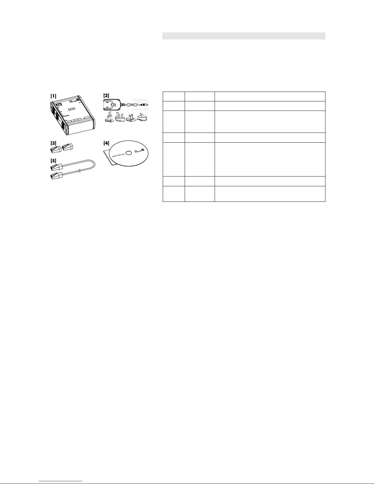
1.3. Scope of supply
Before installation and start up please verify the shipment for
completeness and carry out a visual inspection of the packaging and
the individual items listed below for obvious damage during shipment.
NOTICE: If there are any signs of obvious damage to the items, do not
connect and operate the device.
Qty. d&b Code Description
1 Z6124
R70 Ethernet to CAN interface [1]
1
Power supply [2] including 4 x AC input plugs
specific to the following territorial regions:
Europe, UK, USA, and Australia
2 Z6116
RJ 45 M Terminator [3]
1
CD-ROM [4] containing the R70 manuals and
additional documentation (TI 312).
Additionally, the AcrobatReader® in its current
version is provided to allow the documents to be
displayed and printed.
1
Ethernet cable 2 m/6.5 ft (CAT6, 4 Pair STP) [5]
1 Additional cable clip to be used as cord grip for the
power supply.
(1.4 EN) Page 5 of 20
R70 Ethernet to CAN interface d&b audiotechnik GmbH
1.4. Technical specification
Power supply
Supply voltage.............10 V to 30 V DC / 330 mA, or PoE (Power over Ethernet)
DC IN (barrel connector)..........................to accept coaxial plug 2.1 x5.5 x 9.5 mm
......................................................................................................Center Positive Standard
Operating conditions
Temperature range.....................................– 40° C to + 50° C (– 40° F - + 122° F)
Controls and indicators
Termination.........................................................................built-in switchable terminator
..................Termination of CAN-Bus with internal resistor 120 Ω / 1/4 W / ± 5%
.............................................................................................with corresponding status LED
Indicators (Status LEDs)....................................ON, CAN, ERROR, LAN, TERMINATE
Connectors
LAN (Ethernet)....................................................................................1 x RJ 45 connector
CAN....................................................................2 x RJ 45 connectors, wired in parallel
Hardware
Controller.......................................................................................................................16 Bit
Program Flash.............................................................................................................256 kB
Data Flash.......................................................................................................................8 MB
SRAM Size...................................................................................................................256 kB
EEPROM Size...................................................................................................................8 kB
Additional features.................................................................CAN galvanically isolated
CAN Specification
......................................................................................................................................2.0 A/B
CAN-Bus coupling............................................High Speed, according to ISO 11898
...............................................................................................................galvanically isolated
Max. CAN Baud Rate............................................................................................1 Mbit/s
Ethernet Specification
Ethernet..........................................................................10/100 M Base-F, IEEE 802.3u
Power over Ethernet (PoE)............................................................................IEEE 802.3af
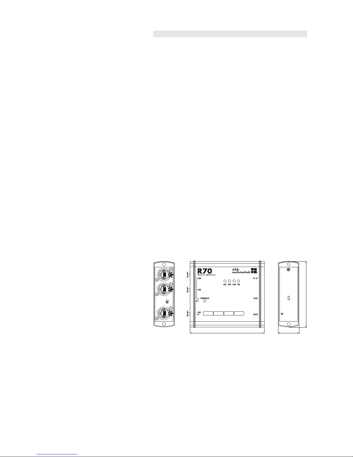
Housing/Dimensions/Weight
Housing.................................................................................................Extruded aluminium
Dimensions (height x width x depth).............115x110x35 mm [4.5" x 4.3" x 1.4"]
Weight.............................................................................................................230 g (0.5 lb)
114 [4.5"] 35 [1.4 "]
109 [4.3"]
Fig. 1: Dimensions in mm [inch]
Additional accessories
Z6123 Bopla mounting clamp upright.....................................................wall mounting
...............................................................................................top hat rail mounting (TS 35)
Page 6 of 20 R70 Ethernet to CAN interface, Manual
 Loading...