

- preliminary -
DS
DS20
Manual 0.1 en

o
d
u
c
t
General information
DS20 Manual - preliminary -
Version: 0.1 en, 02/2019, D2743.EN .01
Copyright © 2019 by d&b audiotechnik GmbH; all rights
reserved.
Keep this document with the product or in a safe place
so that it is available for future reference.
We recommend you to regularly check the d&b website for the
latest version of this document.
When reselling this product, hand over this document to the new
owner.
If you supply d&b products, please draw the attention of your
customers to this document. Enclose the relevant documents with
the systems. If you require additional documents for this purpose,
you can order them from d&b.
d&b audiotechnik GmbH
Eugen-Adolff-Straße 134, D-71522 Backnang, Germany
T +49-7191-9669-0, F +49-7191-95 00 00
docadmin@dbaudio.com, www.dbaudio.com

Explanation of graphical symbols
The lightning symbol within a triangle is intended to alert
the user to the presence of uninsulated "dangerous
voltages" within the unit’s chassis that may be of
sufficient magnitude to constitute a risk of electric shock
to humans.
The exclamation point within a triangle is intended to
alert the user to the presence of important operating and
service instructions in the literature accompanying the
product.
Before using this product, carefully read the
applicable items of the following safety instructions.
1. Keep these instructions for future reference.
2. Read these instructions.
3. Heed all warnings.
4. Follow all instructions.
5. Keep water or other liquids away from the unit. Do not place
liquid filled containers, for example beverages, on top of the
unit.
6. Do not operate the unit while it is wet or standing in liquid.
7. Always operate the unit with the chassis ground wire
connected to the electrical safety earth. Do not defeat the
safety purpose of a grounding-type plug. A grounding-type
plug has two blades and a third grounding prong. The third
prong is provided for your safety. If the provided plug does
not fit into your outlet, consult an electrician for replacement of
the obsolete outlet.
8. Do not use this unit if the power cord is damaged or frayed.
Protect the power cord from being walked upon or pinched,
particularly at the plugs and the point where it exits from the
apparatus.
9. The unit is intended for use in a 19" rack. Follow the mounting
instructions. When a rack on wheels is used, exercise caution
when moving the loaded rack to avoid injury from tipping
over.
10. Unplug this apparatus during lightning storms or when unused
for long periods of time.
11. Lay all cables connected to the unit carefully so that they
cannot be crushed by vehicles or other equipment and that no
one can either step on them or trip over them.
12. Refer all servicing to qualified service personnel. Servicing is
required when the apparatus has been damaged in any way
such as:
– Power-supply cord or plug is damaged.
– Liquid has been spilled into the unit.
– An object has fallen into the unit.
– The unit has been exposed to rain or moisture.
– The unit does not operate normally.
– The unit was dropped or the chassis is damaged.
– Do not remove top or bottom covers. Removal of the covers
will expose hazardous voltages. There are no user
serviceable parts inside and removal may void the warranty.
13. Use the mains plug as the disconnecting device and keep it
readily accessible. If the mains plug is not readily accessible
due to mounting in a 19" rack, then the mains plug for the
entire rack must be readily accessible.
14. An experienced user must always supervise the equipment,
especially if inexperienced adults or minors are using the
equipment.
IMPORTANT SAFETY INSTRUCTIONS
d&b DS20 Manual 0.1 en - preliminary - 3

1 DS20 Audio network bridge........................................... 5
1.1 Intended use................................................................................ 5
1.2 Scope of supply.......................................................................... 5
2 Technical specifications...................................................... 6
3 Startup...................................................................................... 7
3.1 Overview..................................................................................... 7
3.2 Rack mounting and cooling....................................................... 8
3.3 Mains connection....................................................................... 8
3.4 Front panel.................................................................................. 9
3.4.1 DIGITAL OUT 1 – 4................................................................ 9
3.4.2 DIGITAL IN 1 – 4................................................................... 9
3.4.3 ETH1 - ETH4............................................................................ 9
3.4.4 Mode push button................................................................ 10
3.4.5 BYPASSED/SUBSCRIBED/IDENTIFY/SYNC ERROR........ 10
3.5 Rear panel................................................................................ 11
3.5.1 ETH 5/MODE ETH 3........................................................... 11
3.5.2 DIGITAL OUT 5 – 16........................................................... 11
4 References............................................................................ 12
4.1 Meta data................................................................................. 12
4.2 DS20 Firmware update........................................................... 12
5 Manufacturer's Declarations........................................ 13
5.1 EU declaration of conformity (CE symbol)............................. 13
5.2 WEEE Declaration (Disposal).................................................. 13
Contents
d&b DS20 Manual 0.1 en- preliminary -4
1.1 Intended use
The d&b DS20 is a 16 output channel break-out box connecting
the Milan audio network to the AES3 digital audio standard.
In addition, 4 x AES3 input channels are provided for use as a
simple break-in box, e.g. at Front of House.
Configuration and control of the device is performed using the
Milan Controller software, which enables network wide routing
from one single software platform. You can find download
information for this (free) software at
www.dbaudio.com.
The DS20 is mainly intended for use within the d&b Touring rack
assemblies.
NOTICE!
Acoustic interference and malfunctions may occur if the unit is
operated in the immediate vicinity of high-frequency transmitters
(e.g. wireless microphones, mobile phones, etc.). Damage to the
device is unlikely, but cannot be excluded.
1.2 Scope of supply
Before starting up the device, please verify the shipment for
completeness and proper condition of the items.
If there is any sign of obvious damage to the unit and/or the
power cord, do not operate the unit and contact your local dealer
from whom you received it.
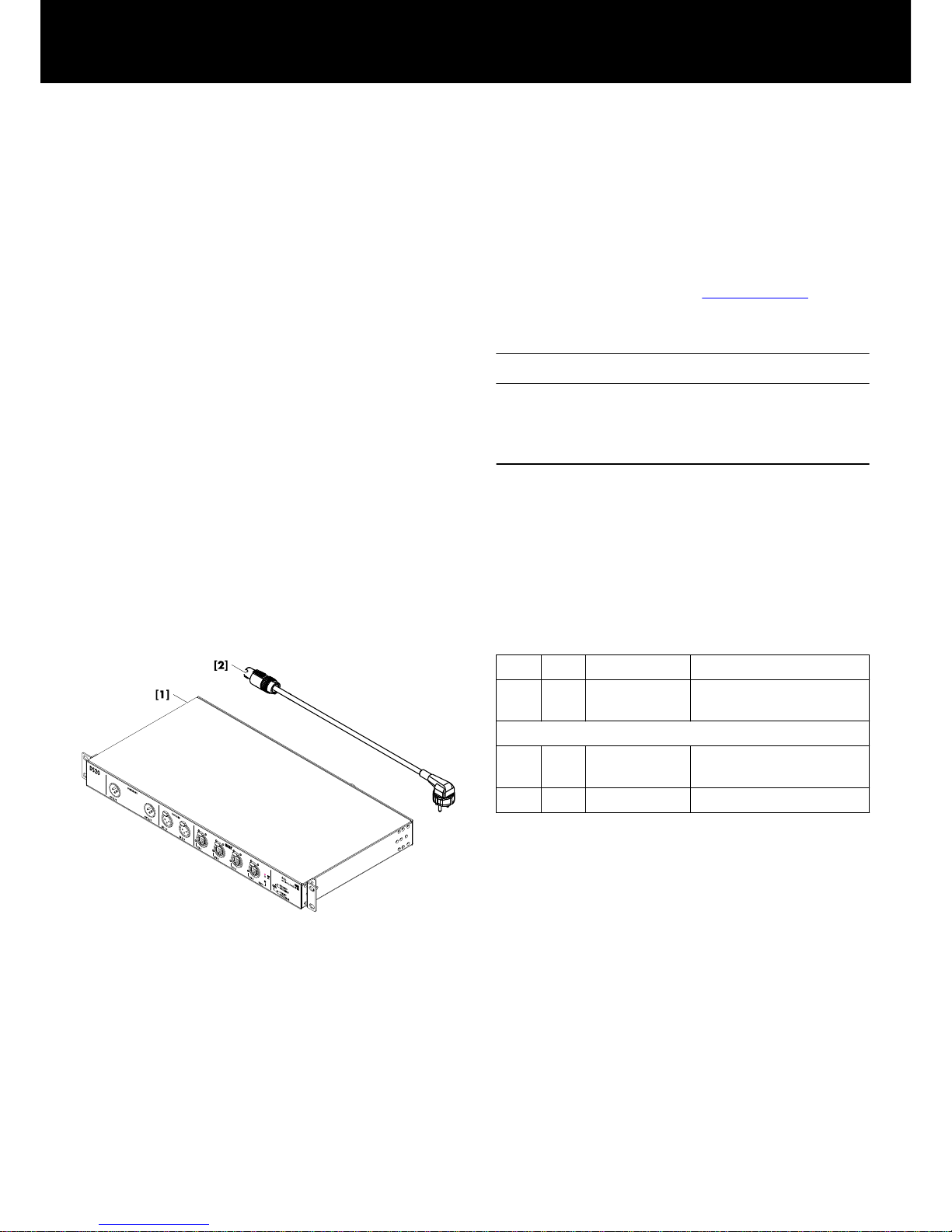
Z4011 DS20
Pos.
Qty. d&b Code Description
[1] 1 Z4011 d&b DS20
Audio network bridge.
Including:
[2] 1 Z2610.xxx Power cord
(specific to country).
1 D2743.EN .01 DS20 Manual.
1 DS20 Audio network bridge
d&b DS20 Manual 0.1 en - preliminary - 5

Power supply
Mains connector
powerCON
®
Rated mains voltage 100 to 240 V, 50 – 60 Hz
Overvoltage protection Up to 400 V AC
Power consumption 10 W (max)
Digital inputs
DIGITAL IN 4 channel (2 x AES3)
3 pin XLR female
Pin assignment 1 = GND, 2 = AES Signal, 3 = AES Signal
Input impedance 110 ohms
Sampling rate 32 – 192 kHz
Synchronization Sample Rate Converter (SRC)
Digital outputs
DIGITAL OUT
16 channels (8 x AES3)
3 pin XLR male
Pin assignment 1 = GND, 2 = AES Signal, 3 = AES Signal
Output impedance 110 ohms
Sampling rate 48/ 96 kHz
Synchronization Milan network
Network
Connectors
etherCON
®
built-in 5-port AVB Ethernet switch
100/1000 Mbit
Controls and indicators
Mode
Push-button
Switch port modes/Audio loss RGB LEDs
BYPASSED/SUBSCRIBED (Rx subscription) LED indicator green
IDENTIFY/SYNC ERROR LED indicator red
Operating conditions
Temperature range
0 °C ... 40 °C / 32 °F ... 104 °F
Storage temperature –20 °C ... 70 °C / –4 °F ... 158 °F
Humidity (rel.), long term average 70%
Dimensions and weight
Height x width x depth
1 RU x 19" x 232 mm
1 RU x 19" x 9.1"
Weight 3.8 kg / 8.37 lb
2 Technical specifications
d&b DS20 Manual 0.1 en- preliminary -6

3.1 Overview
Front panel
[1] XLR male digital outputs 1-4 (AES3).
Refer to Þ Chapter 3.4.1 "DIGITAL
OUT 1 – 4" on page 9.
[2] XLR female digital inputs 1-4 (AES3)
with Sample Rate Converters (SRCs)
Refer to Þ Chapter 3.4.2 "DIGITAL
IN 1 – 4" on page 9.
[3]
etherCON® Ethernet switch ports 1-4
with dedicated indicators for:
▪ Ethernet link/Activity indicator.
▪ Ethernet Gigabit indicator.
▪ Switch port mode indicator.
Refer to Þ Chapter 3.4.3 "ETH1 ETH4" on page 9.
[4] Mode switch.
Refer to Þ Chapter 3.4.4 "Mode
push button" on page 10.
[5] BYPASSED/SUBSCRIBED indicators.
Refer to Þ Chapter 3.4.5
"BYPASSED/SUBSCRIBED/
IDENTIFY/SYNC ERROR"
on page 10.
[6] IDENTIFY/SYNC ERROR indicators.
Refer to Þ Chapter 3.4.5
"BYPASSED/SUBSCRIBED/
IDENTIFY/SYNC ERROR"
on page 10.
Rear panel
[7]
powerCON® Mains connector socket.
Refer toÞ Chapter 3.3 "Mains
connection" on page 8 .
[8]
etherCON® Ethernet switch port 5.
Refer to Þ Chapter 3.5.1 "ETH 5/
MODE ETH 3" on page 11.
[9] XLR male digital outputs 5-16 (AES3).
Refer to Þ Chapter 3.5.2 "DIGITAL
OUT 5 – 16" on page 11.
3 Startup
d&b DS20 Manual 0.1 en - preliminary - 7

3.2 Rack mounting and cooling
Rack mounting
The enclosure provides six different positions for the rack ears
enabling different rack mounting options inside a d&b Touring rack
assembly or any other rack assembly.
The corresponding positions and their intended purpose are shown
in the table below:
Flat:
Intended for any rack assembly.
Pos. 1:
Used when mounted above the I/O panel.
Pos. 2:
Used when mounted above the amplifier.
In addition, the device can also be mounted to the rear of a rack,
provided the required mounting rails are available.
For this purpose the side panels also provide the same mounting
hole options (grid) at the rear as shown in the graphic opposite.
Cooling
Thermal conditions are a vital factor to ensure operational safety of
the device. The DS20 is equipped with an fan that draws cool air
from one side panel into the housing and channel the warm air
towards the rear vents of the device.
▪ Please ensure that adequate cool airflow is provided.
▪ Do not block or cover the rear panel vents on the side panel air
intake.
▪ If the DS20 is installed in sealed cabinets (e.g. in fixed
installations), use additional fan modules with filters that can be
easily replaced without opening the sealed cabinets.
3.3 Mains connection
WARNING!
Potential risk of electric shock.
The device is a protective class 1 unit. A missing earth (ground)
contact may cause dangerous voltages in the housing and controls
and may lead to electric shock.
▪ Connect the device to mains power supplies with protective
earth only.
▪ If there is any sign of obvious damage to the power cord
and/or mains plug, do not use the power cord and replace it
before further use.
▪ Please ensure the mains connector is accessible at any time to
disconnect the device in case of malfunction or danger.
Before connecting the device to mains voltage, check that the
mains voltage and frequency correspond to the specifications on
the rating label above the mains connector socket on the rear
panel of the unit.
A powerCON® mains connector socket [7] is fitted on the rear
panel and an appropriate power cord [2] is supplied.
d&b DS20 Manual 0.1 en- preliminary -8

3.4 Front panel
3.4.1 DIGITAL OUT 1 – 4
Two digital output connectors (OUT 1/2 and OUT 3/4) are
provided and are intended to feed the AES signal to the inputs
D1/2 and D3/4 of the I/O panel within a d&b Touring rack
assembly.
3.4.2 DIGITAL IN 1 – 4
In addition, two digital input connectors (IN 1/2 and IN 3/4) are
provided to allow the signal bridge to act as a break-in box with a
maximum of four AES3 input channels per signal bridge.
Note: Sample Rate Converters (SRC) are used internally on
both inputs.
3.4.3 ETH1 - ETH4
The DS20 provides a 5-port AVB Ethernet switch for different
network topologies, redundancy and advanced functions.
Four connectors (ETH1 - ETH4) are provided on the front panel
while a fifth port (ETH 5) is provided on the rear panel.
The device supports two different switch modes, which are
intended for different applications and network topologies.
According to the mode, the Ethernet ports assume different roles,
which are listed in the table below:
Note: The switch modes can be also accessed from
"Milan Controller Þ Device Þ Configuration".
Mode
ETH 1 ETH 2 ETH 3 ETH 4 ETH 5
Switched Primary Primary Primary Primary Primary
Redundant Primary Secondary Primary Secondary Primary
d&b DS20 Manual 0.1 en - preliminary - 9

LED indicators
Each etherCON® connector provides the following LED indicators:
[3a] Ethernet link/Activity indicator (green).
[3b] Ethernet Gigabit indicator (yellow).
[3c] Switch port mode indicator (RGB-LED).
The color coding is as follows:
▪ Magenta: PRImary.
▪ White: SECondary.
In addition, the switch mode indicator on each port flashes when
the signal bridge detects a subscribed audio channel is not
available on that port, in this way allowing for faster network
troubleshooting. For example, if the Secondary link of the mixing
console is interrupted, the switch mode indicators of the ports
configured as Secondary will flash.
3.4.4 Mode push button
Apart from the Milan Controller software, the device can also be
configured locally via the «Mode» push button.
Briefly pushing the button enters IDENTIFY mode Þ Milan
Controller.
To configure the device locally, proceed as follows:
1. Push the «Mode» button for 2 seconds.
↳
The device enters configuration mode with the current mode
selected and all LEDs will flash.
2. To set the desired configuration (switch mode), briefly push the
«Mode» button to step through the different switch modes.
The following switch mode order will apply:
Default:
PRI/SEC - Bypass off.
PRI: All - Bypass off.
PRI/SEC: Bypass on (Þ SUBSCRIBED LED flashes).
PRI: All - Bypass on (Þ SUBSCRIBED LED flashes).
3. Once the desired switch mode is selected, wait for 5 seconds.
↳
The set mode will be applied automatically.
3.4.5 BYPASSED/SUBSCRIBED/IDENTIFY/SYNC ERROR
BYPASSED
Flashes green when the device is BYPASSED.
The digital inputs are routed (with negligible
latency) to all outputs. That means Inputs 1-4
are routed simultaneously to outputs 1-4, 5-8,
9-12 and 13-16.
SUBSCRIBED
Illuminates green, when any of the signal
bridge outputs has a configured subscription.
IDENTIFY Flashes red to physically identify each DS20
when there is more than one device on the
network.
SYNC ERROR Illuminates red, when the signal bridge cannot
synchronize to the Milan network.
d&b DS20 Manual 0.1 en- preliminary -10

3.5 Rear panel
3.5.1 ETH 5/MODE ETH 3
A fifth Ethernet port is provided on the rear panel which is intended
for the internal Ethernet wiring within a d&b Touring rack assembly.
3.5.2 DIGITAL OUT 5 – 16
In addition, six digital output connectors are provided on the rear
panel to allow further AES channels to be used if more than four
AES channels are required.
d&b DS20 Manual 0.1 en - preliminary - 11

4.1 Meta data
The DS20 sends meta data (Milan channel labels, cabling
information...) via the AES3 outputs alongside the digital audio
samples, using the AES3 User bits.
These meta data can be read out by the d&b four channel
amplifiers (DS labels).
In addition, these meta data can also be displayed in R1 via the
d&b Remote network.
For more information, please refer to the respective amplifier
manuals and/or the R1 Help system.
4.2 DS20 Firmware update
NOTICE!
Only use firmware files provided by d&b. Using firmware files not
provided by d&b can result in the DS20 becoming unusable.
Firmware update files are provided by d&b at www.dbaudio.com.
We recommend you to regularly check the d&b website for the
latest firmware version together with the update procedure
instructions.
4 References
d&b DS20 Manual 0.1 en- preliminary -12

5.1 EU declaration of conformity (CE symbol)
This declaration applies to:
d&b DS20 Audio network bridge, Z4011
All products of type DS20 starting from variant Z4011 .000 are
included, provided they correspond to the original technical
version and have not been subject to any later design or
electromechanical modifications.
We herewith declare that said products are in conformity with the
provisions of the respective EC directives including all applicable
amendments.
A detailed declaration is available on request and can be ordered
from d&b or downloaded from the d&b website at:
www.dbaudio.com.
5.2 WEEE Declaration (Disposal)
Electrical and electronic equipment must be disposed of separately
from normal waste at the end of its operational lifetime.
Please dispose of this product according to the respective national
regulations or contractual agreements. If there are any further
questions concerning the disposal of this product, please contact
d&b audiotechnik.
5 Manufacturer's Declarations
d&b DS20 Manual 0.1 en - preliminary - 13

D2743.EN .01, 02/2019 © d&b audiotechnik GmbH
www.dbaudio.com
- preliminary -
 Loading...