

DS
DS100
Manual 1.3 en

d
u
c
t
General information
DS100 Manual
Version: 1.3 en, 02/2018, D2034.EN .01
Copyright © 2018 by d&b audiotechnik GmbH; all rights
reserved.
Keep this manual with the product or in a safe place
so that it is available for future reference.
We recommend you to regularly check the d&b website for the
latest version of this manual.
When reselling this product, hand over this manual to the new
owner.
If you supply d&b products, please draw the attention of your
customers to this manual. Enclose the relevant manuals with the
systems. If you require additional manuals for this purpose, you
can order them from d&b.
d&b audiotechnik GmbH
Eugen-Adolff-Strasse 134, D-71522 Backnang, Germany
T +49-7191-9669-0, F +49-7191-95 00 00
docadmin@dbaudio.com, www.dbaudio.com

1. Scope of supply................................................................... 4
2. DS100 Signal Engine.......................................................... 5
2.1. Intended use............................................................................... 5
2.1.1. Software Terms of Use........................................................... 5
2.2. Application................................................................................. 5
3. Technical specifications.................................................... 6
4. Startup..................................................................................... 8
4.1.
Overview.................................................................................... 8
4.2. Rack mounting and cooling...................................................... 9
4.3. Connections............................................................................. 10
4.3.1. Mains connection................................................................ 10
4.3.2. ETHERNET............................................................................ 11
4.3.3. USB....................................................................................... 11
4.3.4. AUDIO NETWORK............................................................. 11
4.4. Controls and indicators........................................................... 12
4.4.1. Mains power switch............................................................. 12
4.4.2. POWER button and indicator............................................. 12
4.4.3. ETHERNET indicators........................................................... 13
4.4.4. AUDIO NETWORK indicators............................................ 13
5. Initial setup......................................................................... 14
5.1.
Web Remote interface............................................................ 14
5.1.1. Web Remote interface page............................................... 15
6. Basic setup.......................................................................... 17
7. Service/Maintenance and care.................................. 18
7.1.
Service..................................................................................... 18
7.2. Maintenance and care........................................................... 18
8. Manufacturer's Declarations....................................... 19
8.1.
EU declaration of conformity (CE symbol)............................ 19
8.2. WEEE Declaration (Disposal)................................................. 19
8.3. Licenses and Copyright........................................................... 19
Contents
d&b DS100 Manual 1.3 en 3
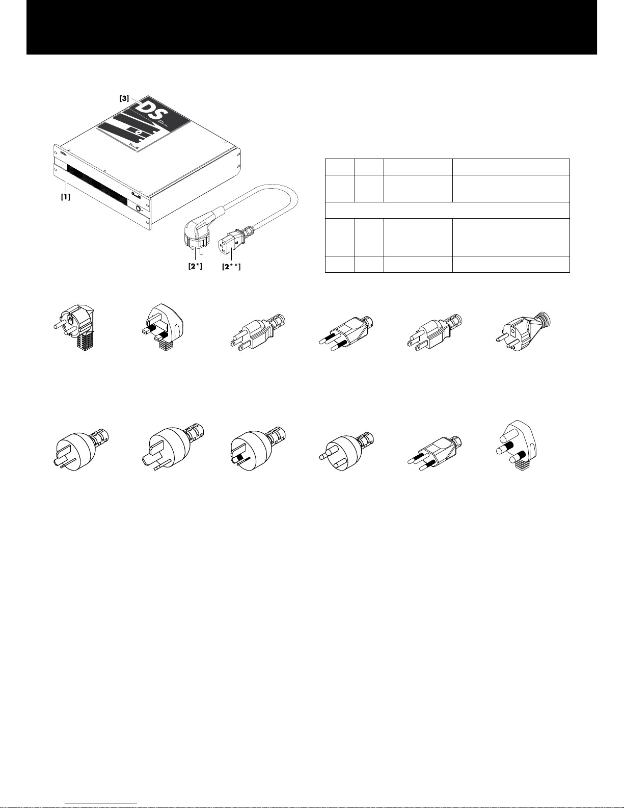
Before starting up the device, please verify the shipment for
completeness and proper condition of the items.
If there is any sign of obvious damage to the unit and/or the
power cord, do not operate the unit and contact your local dealer
from whom you received it.
Pos. Qty. d&b Code Description
[1] 1 Z4100 d&b DS100
Signal Engine
Including:
[2] 1 Z2611.xxx Power cord
(specific to country* with IEC
type** plug)
[3] 1 D2034.EN .01 DS100 Manual
Z2611.000
3-pin Schuko
CE 7/7
IEC Lock**
Z2611.010
3-pin GB
BS 1363A
IEC Lock**
Z2611.020
3-pin USA
NEMA 5-15P
IEC Lock**
Z2611.030
3-pin Swiss
SEV1011
IEC Lock**
Z2611.040
3-pin Japan
NEMA 5-15P
IEC Std.**
Z2611.050
3-pin South Korea
KS C8305
IEC Std.**
Z2611.060
3-pin Argentina
IRAM 2073
IEC Std.**
Z2611.070
3-pin China
GB 2099
IEC Std.**
Z2611.080
3-pin Australia
AS 3112
IEC Std.**
Z2611.100
3-pin Denmark
Afsnit 107-2-D1
IEC Std.**
Z2611.110
3-pin Brazil
NBR 14136
IEC Std.**
Z2611.120
3-pin South Africa
SANS 164-1
IEC Std.**
*Mains plug types and associated standards / **IEC type
IEC Lock: Lockable IEC plug
IEC Std.: Standard IEC plug
(Illustrations are approximations only and not true to scale)
1. Scope of supply
d&b DS100 Manual 1.3 en4
2.1. Intended use
The d&b DS100 Signal Engine is a specialized 3 RU, 19" rack
mount audio processor with Audinate Dante audio networking.
In its base configuration, it provides a 64 x 64 level / delay audio
matrix. Additional software modules provide dynamic source
positioning and emulated acoustics functions.
NOTICE!
The device complies with the electromagnetic compatibility
requirements of EN 55103 (product family standard for audio,
video, audio-visual and entertainment lighting control apparatus for
professional use) for the environments E1 (residential), E2 (business
and commercial), E3 (outdoor use in urban areas) and E4
(outdoor use in rural areas).
Acoustic interferences and malfunctions may occur if the unit is
operated in the immediate vicinity of high-frequency transmitters
(e.g. wireless microphones, mobile phones, etc.). Damage to the
device is unlikely but cannot be excluded.
2.1.1. Software Terms of Use
The software modules installed on the DS100 shall only be used to
the extent intended/documented. d&b shall not be liable for any
damage resulting from any other or non-conforming use.
You may not decompile, copy, alter or enhance the software
modules installed on the DS100or their source codes in any form.
d&b will investigate any infringement of copyright or intellectual
property rights.
2.2. Application
The DS100 Signal Engine is a versatile tool for large and complex
audio systems that are used to route and distribute a large number
of audio channels to many different amplifier channels, break out
rooms, loudspeaker zones, or positions.
The DS100 completely integrates with the overall d&b system
approach which includes loudspeakers, amplifiers, rigging,
transport and networking accessories, and the DS10 Audio
network bridge. The DS10 interfaces between Dante audio
networking and the AES3 inputs of the d&b amplifiers.
d&b audio systems including the DS100 are designed and
optimized using the d&b ArrayCalc simulation software and are
controlled using the d&b R1 Remote control software.
The comprehensive input processing provides Gain, EQ, Delay,
Mute and Polarity switches enabling the user to combine all types
of input signals to create a mix of audio signals from a wide variety
of sources. Extended processing capabilities are also provided on
every output.
The audio matrix with level, mute, and delay controls at every
crosspoint is a very flexible tool to either simply distribute audio
signals to the intended output or, if the crosspoint delay is enabled,
to position audio sources in a distributed loudspeaker setup.
2. DS100 Signal Engine
d&b DS100 Manual 1.3 en 5

Power supply
Universal range switched mode power supply
Mains connectoin IEC type socket
Rated mains voltage 100 to 240 V, 50 – 60 Hz
Nominal power 400 W
Power consumption 200 W (max)
Thermal and Environmental conditions
IP class IP20
Operating temperature range 0 °C to 50 °C
32 °F to 122 °F
Storage temperature range –20 °C to 70 °C
–4 °F to 158 °F
Operating humidity range (rel. non-condensed) 10% to 85%
Storage humidity range (rel. non-condensed) 15% to 90%
Fan noise emission
Idle (@ 22 °C / 71.6 °F)
36 dB(A)
Full load (@ 22 °C / 71.6 °F) 42 dB(A)
Full load (@ 50 °C / 122 °F) 54 dB(A)
Dimensions and weight
Height x width x depth
3 RU x 19" x 481 mm
3 RU x 19" x 18.93"
Weight 11.2 kg / 24.7 lb
Connections
ETHERNET
1 x RJ 45
LAN 100/1000 Mbps
OCA/AES70
OSC
SNMP
AUDIO NETWORK Dante audio network/AES67
2 x RJ 45 for Dante Primary/Secondary
Gigabit only
USB USB 3.0 port
Controls and indicators
Mains power switch
Rocker switch on rear panel
POWER Push-button switch with integrated ring-LED indicator
Boot time Appr.: 45 sec.
I/O
Sample rate for I/O 48 kHz
Inputs 64
Outputs 64
Latency
Dante In to Out < 1.5 ms @ 48 kHz
plus Dante network latency
Input processing
Gain –120 dB ... +24 dB
Polarity 0 °/180 °
EQ 8-band PEQ with high/low shelf
Delay Up to 500 ms
Mute On / Off
Matrix processing
Crosspoint Mute
On / Off
Crosspoint Level –120 dB ... +10 dB
Crosspoint Delay Up to 500 ms
Output processing
Gain
–120 dB ... +10 dB
Polarity 0 °/180 °
EQ 16-band PEQ with high/low shelf
Delay Up to 500 ms
Mute On / Off
En-Scene
Input sources
Up to 64
Positioning Static or dynamic (moving)
Control Manual or external
External control OCA/AES70 and OSC
En-Space
Convolvers
Up to 144
Impulse response length Up to 10 seconds
3. Technical specifications
d&b DS100 Manual 1.3 en6

DS100 dimensions in mm [inch]
d&b DS100 Manual 1.3 en 7

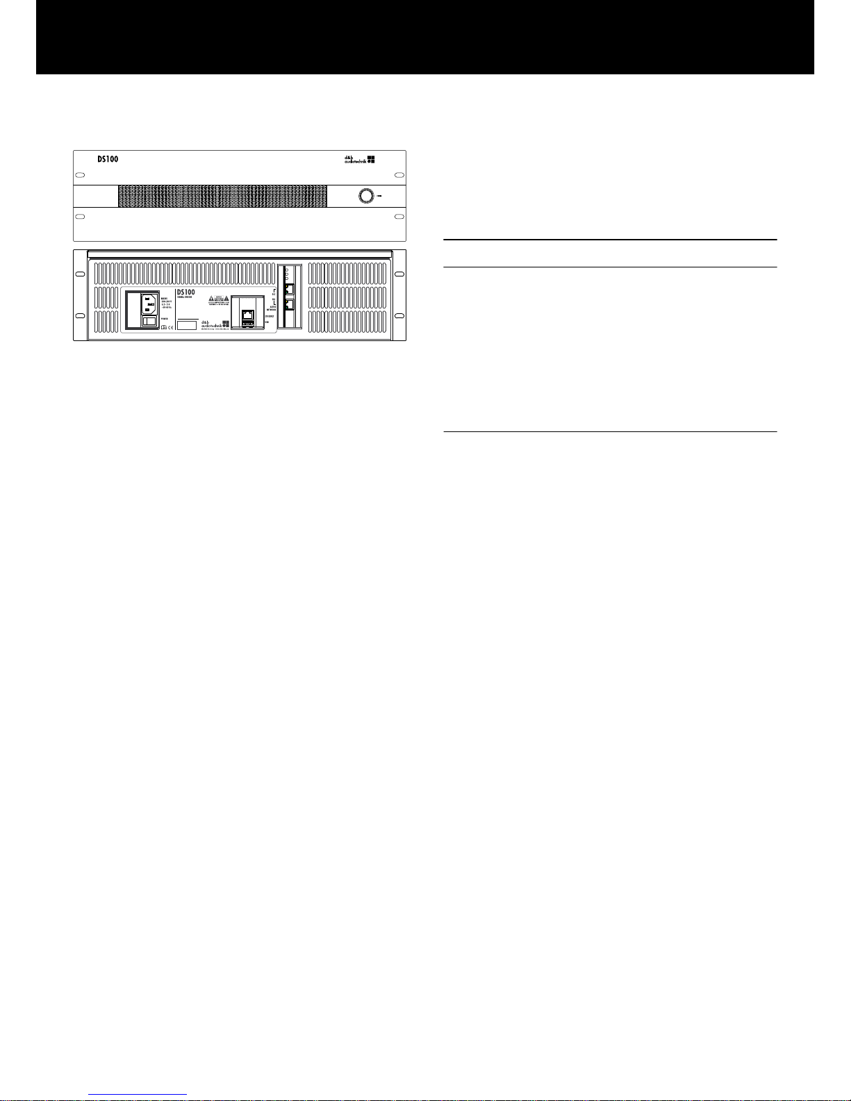
4.1. Overview
Connections
[1] IEC mains connector socket
Refer to Þ Chapter 4.3.1. "Mains
connection" on page 10.
[2] ETHERNET (LAN port)
Refer to Þ Chapter 4.3.2.
"ETHERNET" on page 11 .
[3] USB (USB 3.0 port)
Refer to Þ Chapter 4.3.3. "USB"
on page 11.
[4] AUDIO NETWORK
Dante audio network
Refer to Þ Chapter 4.3.4. "AUDIO
NETWORK" on page 11.
Controls and indicators
[5] Mains power switch
Refer to Þ Chapter 4.4.1. "Mains
power switch" on page 12.
[8] ETHERNET network indicators
Refer to Þ Chapter 4.4.3.
"ETHERNET indicators" on page 13
[9] AUDIO NETWORK indicators
Refer to Þ Chapter 4.4.4. "AUDIO
NETWORK indicators" on page 13.
[6]
[7]
POWER button with integrated power
on indicator
Refer to Þ Chapter 4.4.2. "POWER
button and indicator" on page 12.
4. Startup
d&b DS100 Manual 1.3 en8

4.2. Rack mounting and cooling
Rack mounting
The DS100 enclosure is designed to fit standard 19" equipment
racks or cabinets.
When specifying a rack, be sure to allow extra depth (150 mm /
6" is usually sufficient) to accommodate the cables and connectors
at the rear of the device.
When mounting the DS100 into a 19" rack, do not just rely on
fixing and supporting the device by its front panel using
appropriate rack mounting screws and U washers as shown in the
graphic opposite. Provide additional support ...
▪ by fixing the rear-mounted rack ears using appropriate rack
mounting screws and U washers as shown in the graphic
opposite.
This is particularly important when the device is racked up for
touring purposes.
▪ or using shelves fixed to the inner sides of the cabinet or rack.
Cooling
Thermal conditions are a vital factor to ensure operational safety of
the device. The DS100 is equipped with three internal fans that
draw cool air from the front into the housing and channel the warm
air towards the back of the device.
▪ Please ensure that adequate cool airflow is provided.
▪ Do not block or cover the front panel air intake or the vents on
the rear panel.
▪ If the DS100 is installed in sealed cabinets (e.g. in fixed
installations), use additional fan modules with filters that can be
easily replaced without opening the sealed cabinets.
▪ Do not rack up the DS100 together with other devices
producing additional heat with opposing airflows.
d&b DS100 Manual 1.3 en 9

4.3. Connections
4.3.1. Mains connection
WARNING!
Potential risk of electric shock.
The device is a protective class 1 unit. A missing earth (ground)
contact may cause dangerous voltages in the housing and controls
and may lead to electric shock.
▪ Connect the device to mains power supplies with protective
earth only.
▪ If there is any sign of obvious damage to the power cord
and/or mains plug, do not use the power cord and replace it
before further use.
▪ Please ensure the mains connector is accessible at any time to
disconnect the device in case of malfunction or danger.
If the mains plug is not readily accessible due to mounting in a
19" rack or equipment cabinet, then the mains plug for the
entire rack or cabinet must be readily accessible.
▪ Do not connect or disconnect the IEC mains plug under load or
live.
An IEC type mains connector socket
[1] is fitted on the rear panel.
An appropriate power cord with an IEC type mains plug is
supplied with the device.
Before connecting the device to mains voltage, check that the
mains voltage and frequency correspond to the specifications on
the rating label next to the IEC type mains connector socket [1].
Lockable IEC type mains plug (IEC Lock)
Once the mains plug is connected, it is locked to avoid accidental
disconnection of the device.
To disconnect the power cord, pull the release button [R] towards
you and pull out the mains plug.
d&b DS100 Manual 1.3 en10

4.3.2. ETHERNET
An Ethernet port ( 100/1000Mbps/peer-to-peer) [2] is provided
enabling remote control via Ethernet.
4.3.3. USB
An USB 3.0 port [3] is provided for future functionality.
4.3.4. AUDIO NETWORK
The DS100 provides a fully supported Dante audio network
interface [4] (Gigabit only).
PRImary
RJ45 Ethernet port (Primary):
Used to connect the device to the primary Dante
network to transmit and receive audio.
SECondary RJ45 Ethernet port (Secondary):
Used to connect the device to a secondary network
for redundancy.
The DS100 is Dante Domain Manager (DDM) ready. Further
information on Dante Domain Manager is available at
www.audinate.com.
d&b DS100 Manual 1.3 en 11

4.4. Controls and indicators
4.4.1. Mains power switch
The on/off rocker switch [5] is located on the rear panel.
OFF
Mains isolation is not provided. The mains power supply is
switched off but remains connected to the mains.
ON The mains power supply is switched on and the device is
ready for operation.
4.4.2. POWER button and indicator
Switching on (boot up)
Þ
Provided the mains power switch [5] at the rear is switched
on, pushing the POWER button [6] will boot up the device.
Þ
The integrated LED indicator [7] illuminates green.
Switching off (shut down)
Þ
To switch off (shut down) the device, briefly press the POWER
button.
Þ
After approx. 5 seconds (shut down), the device will be
switched off automatically.
Behavior after AC power interruption
If the AC power is interrupted, the device will remember its last
power state and restore it when the AC power is re-established.
This leads to the following behavior:
AC power interrupted
while device is:
Behavior after reestablishing AC power:
On Device powers up immediately:
Þ Previous 'ON' state restored.
Þ Device keeps 'ON' state.
Off Device powers up immediately:
Þ Previous 'OFF' state
restored.
Þ Device shuts down.
d&b DS100 Manual 1.3 en12

4.4.3. ETHERNET indicators
Status LEDs [8]
Link status / activity LED
Indicates an established link; flashing indicates link activity.
Gigabit link status LED
Indicates an established Gigabit Ethernet link.
4.4.4. AUDIO NETWORK indicators
Dante audio network indicators [9.1/9.2]
Link status / activity LED:
Green indicates an established link; flashing indicates link
activity.
Gigabit link status LED:
Orange indicates an established Gigabit Ethernet link.
Status LEDs [9.3]
The status LEDs indicate the system and clock sync status:
SYS
Indicates the status of the Dante system.
The SYS LED illuminates yellow while the system is
booting. If it remains illuminated, the system has failed to
boot correctly.
The SYS LED color will change to green when the system
has booted successfully and is operating properly.
SYNC Indicates the clock synchronization status of the Dante
device.
Illuminates green to indicate that the device is a Dante
PTP clock slave and is synchronized to the PTP master.
A flashing green light indicates that the device is the
Dante PTP clock master.
Illuminates orange to indicate a network synchronization
error. Obtaining network sync may take up to 45
seconds.
All LEDs flashing green -
All LEDs flash green when the Identify function has been
activated using Dante Controller.
All LEDs illuminating red -
If all LEDs illuminate red, this indicates that the Dante system has
detected errors when booting and has entered failsafe mode.
To restore a device that has entered failsafe mode, use the Dante
Firmware Update Manager (available from the d&b website at
www.dbaudio.com).
d&b DS100 Manual 1.3 en 13

5.1. Web Remote interface
A Web Remote interface is integrated which provides direct access
to the DS100 using a standard web browser.
Note: The DS100 can only be accessed after connecting the
device to a computer via Ethernet. However, this requires to
manually set a static IP address on the PC network interface.
Connect the DS100 and the computer to the same Ethernet
network.
Recommended and tested browsers
Windows: ▪ Firefox V22.0 or higher
▪ Microsoft Internet Explorer V11 or higher
▪ Microsoft Edge V12 or higher
▪ Google Chrome V21 or higher
▪ Opera V15 or higher
macOS: ▪ Safari V6.0 or higher
▪ Firefox V22.0 or higher
▪ Google Chrome V21 or higher
▪ Opera V15 or higher
iOS: ▪ iOS 6 or higher
Android: ▪ Mobile Firefox V27.0 or higher
▪ Android Browser V4.4 or higher
Physical setup
Simply connect the LAN connector port of your computer to the
ETHERNET [2] connector of the device.
Direct connection
To enable access via the Web Remote interface, proceed as
follows:
By factory default, the IP address is set to 192.168.1.100.
To access the device, manually assign an IP address to the
computer in your network in the same subnet as the device.
Proceed as follows:
1. Navigate to the network settings of your computer associated
with your network adapter.
2. Open the corresponding network properties dialog.
3. Enter a static IP address in the same subnet as the device:
IP address:
e.g. 192.168.1.101
Subnet mask: 255.255.255.0
4. Confirm the changes and close the network properties dialog.
5. To display the Web Remote interface page of the device,
enter its IP address in the address bar of your web browser.
Þ
192.168.1.100
5. Initial setup
d&b DS100 Manual 1.3 en14

5.1.1. Web Remote interface page
The Web Remote interface page is split into three tabs: the
«Event Log», «Commands» and «Licenses» tabs.
5.1.1.1. Event Log tab
The «Event Log» stores a maximum of 10000 records. Once the
maximum number of records is reached, the system starts deleting
the first ones Þ Ring buffer.
The number of records displayed depends on the size of the
browser window.
Located on the right-hand side of the record list
are various Navigation buttons allowing you
to scroll through the list using the
«Page Up/Down» or «Line Up/Down» buttons
or by directly jumping to the «Latest» record.
In addition, the editable «Record» field allows
you to enter a dedicated record number. The
corresponding record will be displayed at the
very bottom of the record list.
Storage option ( )
In addition, a storage option is provided which allows you to store
the Event log data locally. This is mainly intended for service
and/or troubleshooting purposes.
To save the Event log data locally, proceed as follows:
1. Select the «Save» button at the bottom right corner of the web
browser window.
Þ
A corresponding dialog will pop up providing you with a
drop-down list from which you can select either the number
(«Last [n]») of records or «All» records to be saved.
2. Choose the desired option from the drop-down list and select
«Save».
Þ
The event log data will be downloaded and the download
progress will be displayed.
Once the download is completed, a corresponding
message will be displayed.
d&b DS100 Manual 1.3 en 15

3. Select «Save» to store the Event log data locally.
Þ
Your web browser will display the corresponding dialog
and the file will be saved as Event.log to the local
download directory you have specified in the download
settings of your browser.
5.1.1.2. Commands tab
This functionality is intended for service purposes only.
5.1.1.3. Licenses tab
Apart from the serial number of the device (Þ
«DS100 serial number»), the «Licenses» tab provides an overview
of the licenses installed on the device (Þ «License status») and
allows new licenses or license updates to be uploaded to the
device (Þ «License update»).
License update
To upload/exchange license keys, proceed as follows:
1. Select the «Download context file» button.
Þ
Your web browser will display the corresponding dialog
and the file will be saved as:
dbaudioDS100_[SerialNumber]_[LicenseKey]_[Date].
rac
to the local download directory you have specified in the
download settings of your browser.
2. Send this file via email to your d&b sales partner.
Þ
He will then send you the new license file:
dbaudioDS100_[SerialNumber]_[LicenseKey]_[Date].
rau.
3. Once you have received the file, select the
«Upload license file» button.
Þ
Your web browser will display the corresponding dialog.
Once the license file is uploaded you can enable or disable your
license keys within R1.
d&b DS100 Manual 1.3 en16

6. Basic setup
d&b DS100 Manual 1.3 en 17

7.1. Service
CAUTION!
Potential risk of explosion.
The device incorporates a lithium battery which may cause danger
of explosion if not replaced correctly.
▪ Refer replacement only to qualified service personnel
authorized by d&b audiotechnik.
Do not open the device. No user serviceable parts inside. In case
of any damage do not operate the device under any
circumstances.
Refer servicing only to qualified service personnel authorized by
d&b audiotechnik. In particular if:
▪ objects or liquids have entered the device.
▪ the device does not operate normally.
▪ the device was dropped or the housing is damaged.
7.2. Maintenance and care
During normal operation, the device provides maintenance-free
service.
Due to the cooling concept, no dust filters are required. As a result,
filter exchange or cleaning is not necessary.
7. Service/Maintenance and care
d&b DS100 Manual 1.3 en18

8.1. EU declaration of conformity (CE symbol)
This declaration applies to:
d&b DS100, Z4100
All products of type DS100 starting from variant Z4100 .000 are
included, provided they correspond to the original technical
version and have not been subject to any later design or
electromechanical modifications.
We herewith declare that said products are in conformity with the
provisions of the respective EC directives including all applicable
amendments.
A detailed declaration is available on request and can be ordered
from d&b or downloaded from the d&b website at:
www.dbaudio.com.
8.2. WEEE Declaration (Disposal)
Electrical and electronic equipment must be disposed of separately
from normal waste at the end of its operational lifetime.
Please dispose of this product according to the respective national
regulations or contractual agreements. If there are any further
questions concerning the disposal of this product, please contact
d&b audiotechnik.
8.3. Licenses and Copyright
This device includes software components released under different
open source licenses. These components are supplied together with
the d&b firmware.
A list of the components and a full-text version of all licenses and
copyrights can be accessed using the Web Remote interface as
described in Þ Chapter 5. "Initial setup" on page 14.
Þ
Selecting the d&b logo at the top left of the «Web Remote»
interface page allows access to the
«Software licenses and copyright» information page.
This page provides an overview of the open source software used
in this product. As required by the GPL and LGPL licenses, we will
send you a copy of the used source code on request. If you would
like to obtain a copy, please contact us by mail to:
d&b audiotechnik GmbH
Eugen-Adolff-Strasse 134, D-71522 Backnang, Germany
T +49-7191-9669-0, F +49-7191-95 00 00,
info@dbaudio.com
or by email at: software.support@dbaudio.com
8. Manufacturer's Declarations
d&b DS100 Manual 1.3 en 19

D2034.EN .01, 02/2018 © d&b audiotechnik GmbH
www.dbaudio.com
 Loading...