


C6/C690
Manual
(3.0E)
General Information
C6/C690 Manual
Version 3.0E, 10/2003, D2077.E.03
©
by d&b audiotechnik AG 2003; all rights reserved.
The information contained in this manual has been carefully
checked for accuracy, at the time of going to press, however no
guarantee is given with respect to the correctness.
d&b audiotechnik AG accepts no responsibility for any errors or
inaccuracies that may appear in this manual or the products and
software described in it.
Technical specifications, dimensions, weights and properties do not
represent guaranteed qualities.
As manufacterers we reserve the right to make alterations and
modifications within the framework of legal provisions, as well as
changes aimed at improving quality.
d&b audiotechnik AG
Eugen-Adolff-Strasse 134, D-71522 Backnang, Germany
Telephone +49-7191-9669-0, Fax +49-7191-95 00 00
E-mail: docadmin@dbaudio.com, Internet: www.dbaudio.com
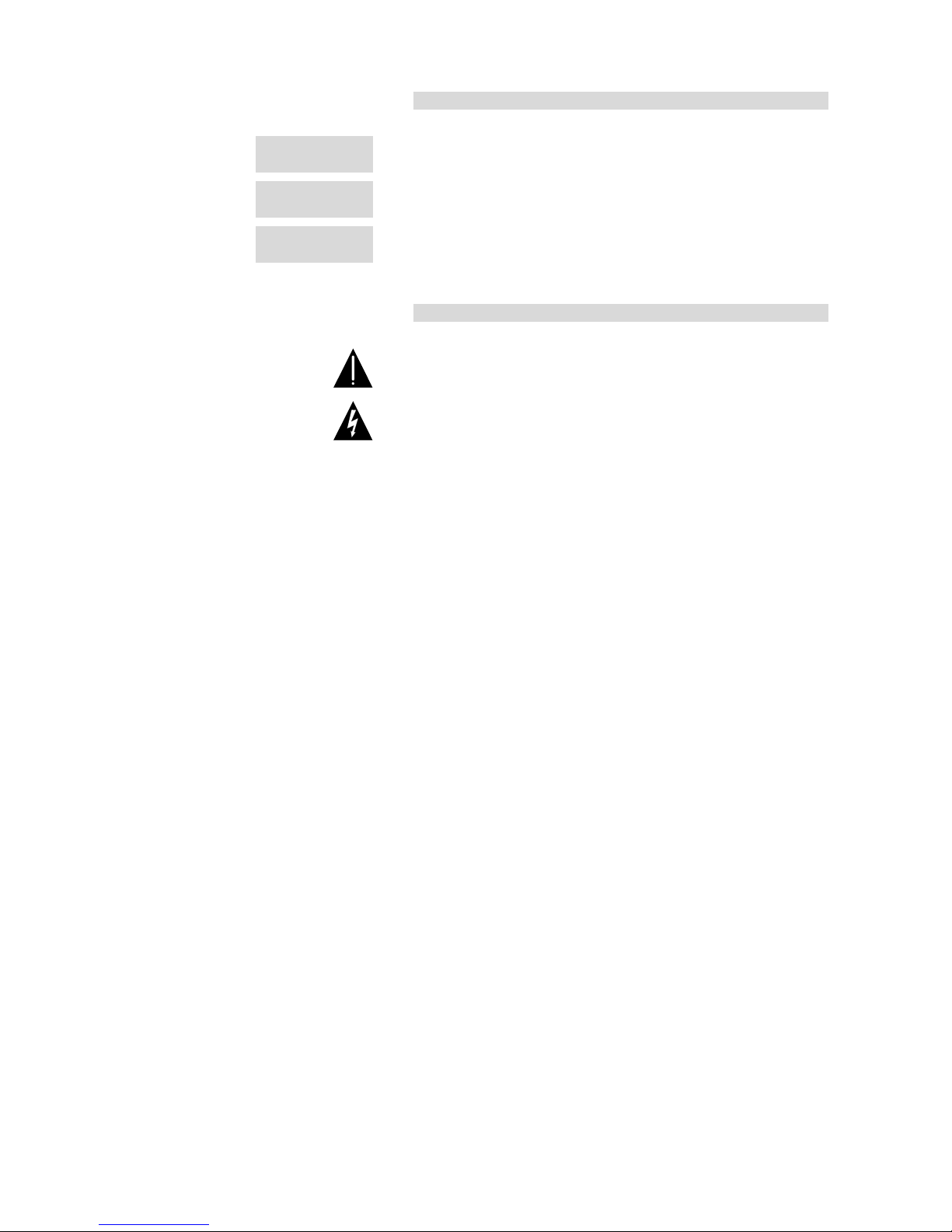
References in the manual
WARNING!
This refers to a potentially dangerous situation
which may lead to personal injury.
CAUTION!
This refers to a potentially dangerous situation
which may lead to damage to the equipment.
IMPORTANT!
This refers to a situation which may cause the
equipment to malfunction.
Symbols on the equipment
Please refer to the information in the operating
manual.
WARNING!
Dangerous voltage!

C6/C690 Manual (3.0E) Page 3 of 8
C6/C690 Manual (3.0E) Safety instructions
Safety precautions
Before you use our products, read the manual
carefully and observe all the safety precautions.
They will protect you and help to avoid equipment
failures.
Keep this manual in a safe place so that it is
available for future reference.
If you supply d&b products, please draw the
attention of your customers to these safety
guidelines. Enclose the relevant manuals with the
systems. If you require additional manuals for this
purpose, you can order them from d&b.
Information regarding use of loudspeakers
WARNING!
Never stand in the immediate vicinity of loudspeakers driven at a
high level. Professional loudspeaker systems are capable of causing
a sound pressure level detrimental to human health. Seemingly noncritical sound levels (from approx. 95 dB SPL) can cause hearing
damage if people are exposed to it over a long period.
In order to prevent accidents when deploying loudspeakers on the
ground or when flown, please take note of the following:
When setting up the loudspeakers or loudspeaker stands, make sure
they are standing on a firm surface. If you place several systems on
top of one another, use straps to secure them against movement.
Only use accessories which have been tested and approved by d&b
for assembly and mobile deployment. Pay attention to the correct
application and maximum load capacity of the accessories as
detailed in our specific “Mounting instructions” or in our "Flying
system and Rigging manuals”.
Ensure that all additional hardware, fixings and fasteners used for
installation or mobile deployment are of an appropriate size and
load safety factor. Pay attention to the manufacturers instructions
and to the relevant safety guidelines.
Regularly check the loudspeaker housings and accessories for visible
signs of wear and tear, and replace them when necessary.
Regularly check all load bearing bolts in the mounting devices.
CAUTION!
Loudspeakers produce a static magnetic field even if they are not
connected or are not in use. Therefore make sure when erecting
and transporting loudspeakers that they are nowhere near
equipment and objects which may be impaired or damaged by an
external magnetic field. Generally speaking, a distance of 0.5 m
(1.5 ft) from magnetic data carriers (floppy disks, audio and video
tapes, bank cards, etc.) is sufficient; a distance of more than 1 m
(3 ft) may be necessary with computer and video monitors.

C6/C690 Manual (3.0E) Page 4 of 8
C6
The C6 loudspeaker is a full range, two-way bass-reflex enclosure
fitted with a 12" LF driver passively connected to a 2" HF
compression driver which is coupled to a 60
°
x 40° CD horn.
The C6 cabinet is constructed from marine plywood and has an
impact resistant paint finish. The front of the loudspeaker cabinet is
fitted with a rigid metal grill covered with a replaceable
acoustically transparent foam. The cabinet top plate has an integral
handle and four M10 threaded inserts for mounting brackets and
rigging. The L shaped metal plate at the bottom of the cabinet also
incorporates a handle, four M10 threaded inserts and a socket to
accept a loudspeaker stand.
Version C690
The C690 has a wider horizontal and vertical dispersion than the
C6, the only difference being the 90
°
x 50° CD horn.
CAUTION!
Only operate C6/C690 cabinets with a d&b D12 or E-PAC
amplifier in C6 mode or a P1200A mainframe fitted with a C6
controller module, otherwise there is a risk of damaging the
loudspeaker components.
Connections
1
2
3
4
5
1
2
3
4
5
passive
crossover
Connector wiring
The C6/C690 cabinets are fitted with a pair of EP5 connectors. All
pins of both connectors are wired in parallel. The C6 uses the pin
assignments 1/2. Pins 3/4 and 5 are designated to d&b active
subwoofers.
Using one connector as the input, the second connector allows for
direct connection to additional cabinets.
The C6/C690 can be supplied with NL4 output connectors as an
option using the pin assignment 1+/1–. Pins 2+/2– are designated
to d&b active subwoofers.
Pin equivalents of EP5 and NL4 connectors are listed in the table
below.
EP5
1 2 3 4 5 (SenseDrive SUB)
NL4
1+ 1– 2+ 2– n.c.
EP5 and NL4 pin assignments

C6/C690 Manual (3.0E) Page 5 of 8
Operation with D12
Selecting C6 mode in the D12 enables up to two C6/C690
cabinets to be driven by each channel. In applications with low
continuous levels and low ambient temperatures up to three
cabinets per channel may be connected.
When the D12 is operated in "Mix TOP/SUB" mode the C6/C690
cabinet and a respective active subwoofer can be linked together
locally and fed by a single 4-wire cable from either amplifier
output connector.
IMPORTANT!
To apply SenseDrive for the subwoofer, EP5 connectors and 5-wire
cables have to be used. When operated in "Mix TOP/SUB" mode
the subwoofer has to be fed from the output B connector of the
D12 amplifier.
Controller settings
For acoustic adjustment the settings CUT, HFA and CPL can be
selected.
CUT
Set to CUT, a high pass filter with a 110 Hz cut off frequency is
inserted in the controller signal path. The C6/C690 is now
configured for use with d&b active subwoofers.
HFA circuit
-5
0
5
10
-10
-15
-20
-25
-30
20
100 1k 10k
20k
Frequency response of HFA circuit
In HFA mode (High Frequency Attenuation), the HF response of the
C6/C690 is rolled off. The HFA provides a natural, balanced
frequency response when a unit is placed close to listeners in near
field or delay use.
High Frequency Attenuation begins gradually at 1 kHz, dropping
by approximately 3 dB at 10 kHz. This roll off mimics the decline in
frequency response experienced when listening to a system from a
distance in a typically reverberant room or auditorium.
CPL circuit
Frequency response of CPL circuit
The CPL (Coupling) circuit compensates for coupling effects
between the cabinets when building closely coupled arrays. CPL
begins gradually at 1 kHz, with maximum attenuation below
250 Hz, providing a balanced frequency response when C6/C690
cabinets are used in arrays of two or more. The function of the CPL
circuit in the D12 amplifier is shown in the diagram opposite and
can be set in dB attenuation values between –9 and 0, or a positive
CPL value which creates an adjustable low frequency boost around
65 Hz (0 to +5 dB).

C6/C690 Manual (3.0E) Page 6 of 8
Operation with E-PAC
REMOTE
LO IMP
DELAY ON
CUT
HFA
SPKR
21345687
ON
E-PAC Configuration for C6
(E-PAC version 2)
To drive C6/C690 cabinets the E-PAC has to be configured to C6
mode.
For an E-PAC version 2, the configuration is selected by setting the
appropriate DIP switches on the rear panel.
For an E-PAC version 3, the configuration is set via the encoder in
conjunction with the LCD. Selecting C6 mode enables one C6/C690
cabinet to be driven at an output power of 300 Watts. LO IMP
mode allows the E-PAC to drive two C6/C690 cabinets with a 6 dB
reduction of input level to the loudspeakers.
The CUT and HFA settings are available. The characteristics of the
CUT and HFA settings are explained under the previous section
"Operation with D12 - Controller settings".
The settings MON and 160 Hz are not available with the E-PAC.
Operation with P1200A
C6
CUT
GRISP
MUTE
OVL
-12 dB
-6
+6
0
MON
160Hz
Controls on C6
controller module
Up to two C6/C690 cabinets can be driven by each P1200A power
amplifier channel fitted with a C6 controller module.
Fitting one C6 and one subwoofer controller module allows a single
mainframe to drive two C6/C690 and two active subwoofer
cabinets. All cabinets can be linked together locally and fed by a
single 4-wire cable from either mainframe output connector.
The CUT, MON and 160 Hz settings are available. The
characteristics of the CUT setting is explained under the previous
section "Operation with D12 - Controller settings".
MON switch and indicator
If the MON switch is selected the low frequency level is reduced by
3 dB. This setting reduces the low frequency energy gained from
the coupling effect of floor placement.
160 Hz setting (CUT and MON switches both selected)
If the 160 Hz mode is selected, a high pass filter is inserted in the
controller signal path. The crossover frequency of 160 Hz is higher
than in CUT mode and thus increases the available headroom in
the C6/C690. The 160 Hz setting can be selected when the C6/
C690 is operated with a d&b subwoofer.
Dispersion characteristics
The diagrams below show dispersion angle vs frequency plotted
using lines of equal sound pressure (isobars) at –6 dB and –12 dB.
The nominal 60
°
horizontal dispersion is maintained from 20 kHz
down to 2 kHz.
C6 isobar diagrams

C6/C690 Manual (3.0E) Page 7 of 8
Technical specifications
C6 (C690) system data
Frequency response (–5 dB)......................................................................70 Hz - 17 kHz
Max. sound pressure (1 m, free field) with D12........................................134 (133) dB
Max. sound pressure (1 m, free field) with E-PAC ...................................131 (130) dB
Max. sound pressure (1 m, free field) with P1200A.................................133 (132) dB
(SPLmax peak, pink noise test signal with crest factor of 4)
Input level (100 dB SPL / 1 m)....................................................................–14 (–13) dBu
Polarity to controller INPUT (XLR pin 2: + / 3: –) ...................................LF: + / HF: –
C6 (C690) loudspeaker
Nominal impedance................................................................................................... 8 ohms
Power handling capacity (RMS / peak 10 ms)........................................ 200 / 800 W
Nominal dispersion angle (hor. x vert.).......................................60
°
x 40° (90° x 50°)
Connections ..................................................................................................................2 x EP5
Pin assignments ...................................................................................................................1/2
optional.........................................................................................................................2 x NL4
Pin assignments .......................................................................................................... 1+ / 1–
Weight .................................................................................................................28 kg (62 lb)
-5
0
5
10
-10
-15
-20
-25
-30
20
100 1k 10k
20k
STANDARD
CUT
160 Hz
C6 frequency response, standard, CUT and 160 Hz switch settings
C6/C690 wiring diagram
C6/C690 cabinet dimensions in mm [inch]

C6/C690 Manual (3.0E) Page 8 of 8
d&b audiotechnik AG, Eugen-Adolff-Str. 134, D-71522 Backnang, Germany, Phone +49-7191-9669-0, Fax +49-7191-95 00 00
EU declaration of conformity (CE symbol)
EU conformity of loudspeakers
This declaration applies to loudspeakers manufactured by d&b
audiotechnik AG and includes the types listed in the table below:
−
C6/C690 Z2252
All production versions of these types are included, provided they
correspond to the original technical version and have not been
subject to any later design or electromechanical modifications.
We herewith declare that said products are in
conformity with the provisions of the following EC
directives including all applicable amendments:
−
89/336 Electromagnetic Compatibility
The following standards have been applied:
−
DIN EN 55013:08-1991
−
DIN EN 55020:05-1995
−
DIN EN 50082-1:03-1993
 Loading...