

ArraySight
A
Manual 1.7 en

General information
ArraySight Manual
Version: 1.7 en, 04/2019, D2735.EN .01
Copyright © 2019 by d&b audiotechnik GmbH; all rights
reserved.
Keep this document with the product or in a safe place
so that it is available for future reference.
We recommend you to regularly check the d&b website for the
latest version of this document.
When reselling this product, hand over this document to the new
owner.
If you supply d&b products, please draw the attention of your
customers to this document. Enclose the relevant documents with
the systems. If you require additional documents for this purpose,
you can order them from d&b.
d&b audiotechnik GmbH
Eugen-Adolff-Straße 134, D-71522 Backnang, Germany
T +49-7191-9669-0, F +49-7191-95 00 00
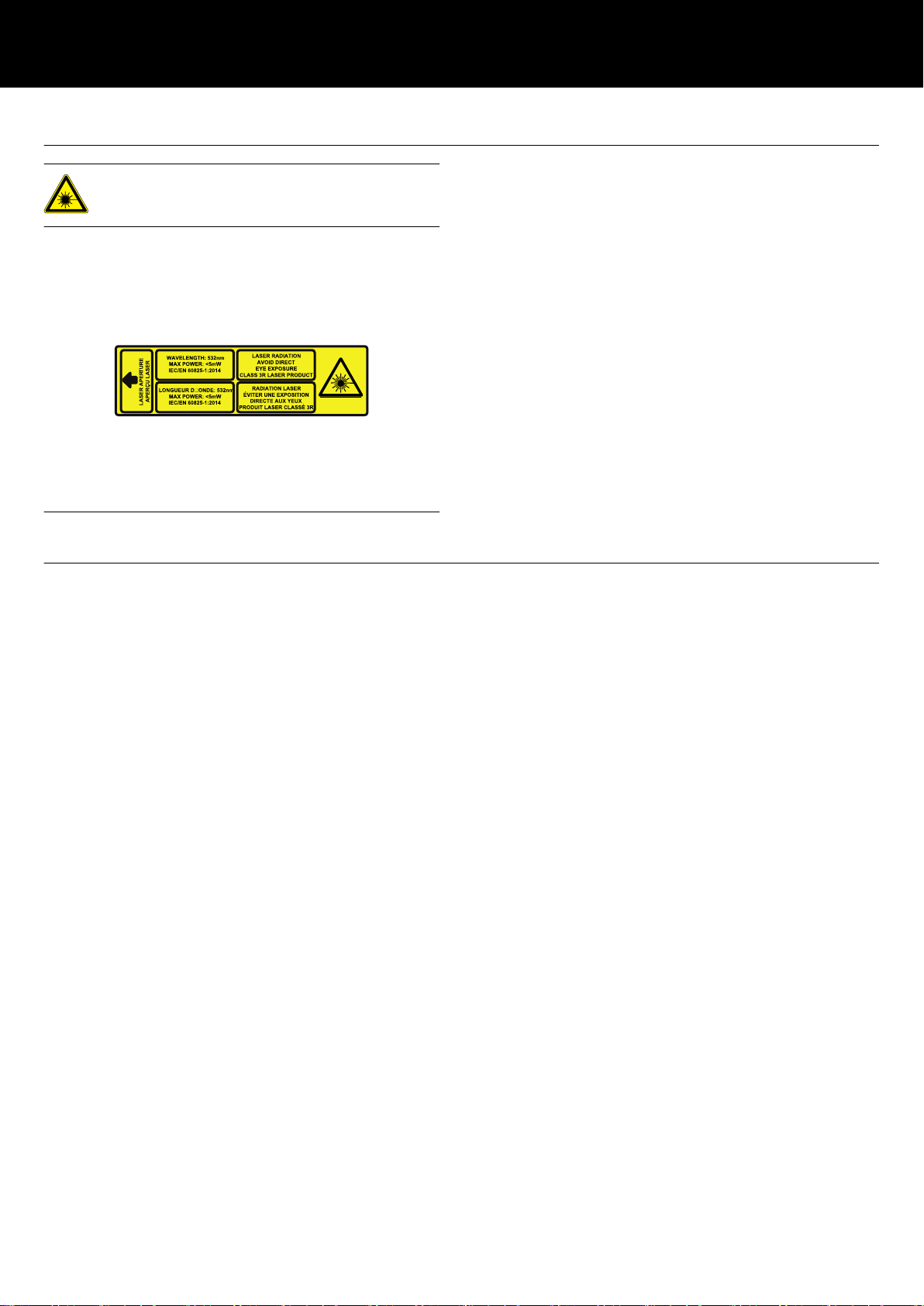
Safety precautions when using laser equipment
WARNING!
Potential risk of damage to the eyes.
Laser class 3R, 532 nm, <5 mW:
Do not suppress eye-closure reflex.
The d&b ArraySight sender unit is shipped with the following label
affixed to the top surface. Do not remove this label under any
circumstances.
The high brightness laser of the sender unit requires additional
safety considerations.
Please give careful attention to the following safety warnings
before using the d&b ArraySight inclinometer system.
NEVER look directly into the laser, even when it is switched off, as
someone may activate it without warning you.
WARN others in the venue that you are going to use a laser and
move them away from the target area before activating a laser.
ENSURE that others do not enter the target area of the laser while
it is in use.
ENSURE that the meter unit is to hand at all times so that the
beam can be switched off immediately if necessary.
ALWAYS use the laser for the minimum amount of time possible.
You can carry out most of the alignment procedure with the laser
turned off.
Disconnect the cable from the meter unit once the measurements
had been made.
ALWAYS ensure that the meter unit is disconnected when the
public have access to the venue.
NEVER leave the laser turned on while unattended.
NEVER use the laser in any other application than it is intended
for.
Operational safety
The d&b ArraySight inclinometer system is an integrated part of the
d&b rigging system and should be regarded with the same respect
as any other rigging component.
The sender unit must be safely mounted to the corresponding
Flying frame when used above 2 m (6.6 ft) from ground level using
the enclosed fixing screws.
DO NOT fix the sender unit with tape or velcro.
When making adjustments to the array with motor hoists, watch the
hoist - not the meter unit! Check the measurement only when the
hoist has finished moving.
When using the meter unit, be aware of other rigging operations
taking place around you. Always follow the appropriate safety
procedures (including wearing the appropriate personal protective
equipment).
The sender unit is weather/water resistant (IP54), enabling it to
withstand dust ingress and rain, although the limited ingress of
water may be possible. It is therefore advisable to take account of
prevailing weather and environmental conditions and take
precautions to protect the sender unit.
As with any rigging components, regular safety inspections are
obligatory.
d&b ArraySight Manual 1.7 en 3

Contents
1 d&b ArraySight..................................................................... 5
1.1 Scope of supply.......................................................................... 5
1.2 Intended use................................................................................ 5
2 Technical specifications...................................................... 7
3 Startup...................................................................................... 8
3.1 Installing the batteries................................................................. 8
3.2 Connecting the units................................................................... 8
3.3 Switching on/switching off......................................................... 9
3.4 User interface of the meter unit.................................................. 9
3.5 The menu structure.................................................................... 10
3.5.1 Home screen......................................................................... 10
3.5.2 Main menu «Menu»............................................................. 10
3.5.3 Meter settings........................................................................ 10
3.5.4 Sender settings...................................................................... 11
3.5.4.1 Editing IP and Remote ID settings..................................... 12
4 Resetting the angle (zeroing) and laser
alignment.............................................................................. 13
4.1 Resetting the angle (zeroing)................................................... 13
4.2 Aligning the laser..................................................................... 14
5 Using the system................................................................ 16
5.1 Measuring the angle................................................................ 16
5.2 Measurement limits.................................................................. 16
5.3 Adjusting angles using relative values.................................... 16
5.4 Using the laser.......................................................................... 17
5.5 Application example................................................................ 17
6 OCA integration (Ethernet)............................................ 18
7 Maintenance and care.................................................... 19
7.1 Cleaning................................................................................... 19
7.2 etherCON connector socket protection.................................. 19
7.3 Calibrating the accelerometer................................................. 20
8 Manufacturer's declarations......................................... 22
8.1 EU declaration of conformity (CE symbol)............................. 22
8.2 WEEE Declaration (Disposal).................................................. 22
8.3 Licenses and Credits ................................................................ 23
9 Appendix.............................................................................. 25
9.1 Z5710.xxx d&b ArraySight sets............................................. 25
9.1.1 Z5710.001 Mounting instructions...................................... 25
9.1.2 Z5710.002 Mounting instructions...................................... 26
d&b ArraySight Manual 1.7 en4
1 d&b ArraySight
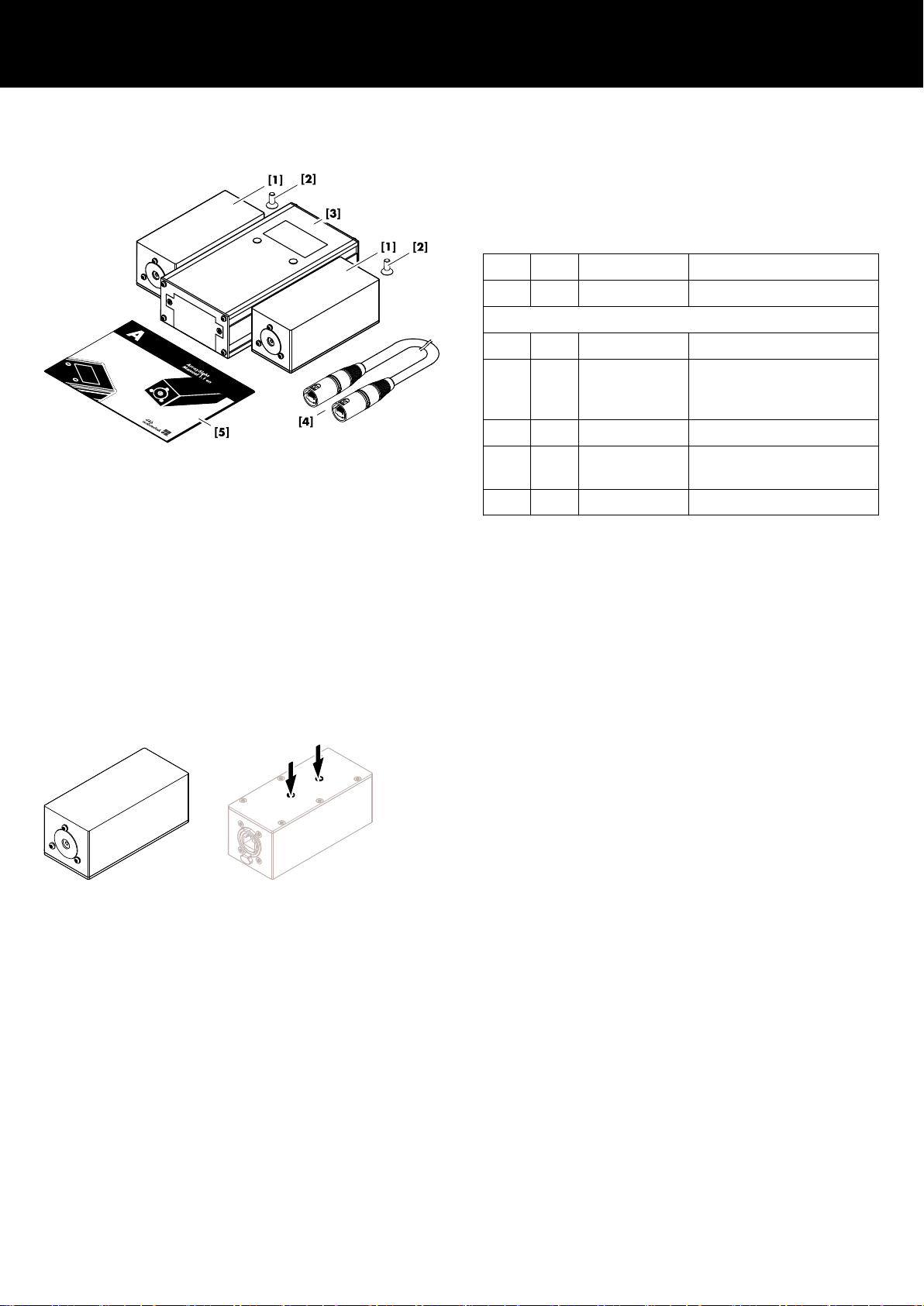
1.1 Scope of supply
Before setting up the system, please verify the shipment for
completeness and proper condition of the items.
If there is any sign of obvious damage, do not operate the units
and contact your local dealer from whom you received the system.
Pos. Qty. d&b Code Description
1 Z5710 d&b ArraySight set
Including:
[1] 2 Z5711 ArraySight sender unit
[2] 2 2 x Fixing screws for each
sender unit
(Torx T20, M4 x 14 mm).
[3] 1 Z5712 ArraySight meter unit
[4] 2 K6006.200.00 Shielded CAT5e 1:1 cable,
30 m (100 ft)
[5] 1 D2735.EN .01 ArraySight Manual
1.2 Intended use
The d&b ArraySight laser inclinometer system is intended to
vertically aim an entire array in its operating position. It provides
precision angle measurement over a wide measuring range of ±90
degrees. The sender unit uses a 3-axis MEMS accelerometer for
data acquisition. This provides accurate tilt sensing over one axis,
even when the unit is tilted on another axis. Accurate angle
measurements can be achieved, resolved to ±0.1 degrees on the
display of the meter unit.
The compact sender unit is housed in a weather resistant enclosure.
It utilizes an ultra bright green laser to provide a visible indication
for aiming the array, with a flashing mode to help locate the beam
in bright surroundings.
The sender unit can be attached to dedicated d&b Flying frames.
For this purpose, the sender unit has two threaded inserts on its
base and comes with dedicated fixing screws (Torx T20, M4 x
14 mm).
Easy calibration
Multiple sender units can be used with one meter unit. Calibration
information is stored in the sender unit using non-volatile memory,
so it remains accurate after the meter unit is disconnected. Sender
units can be reset on the fly to any angle within range, allowing
adjustment of system elevation to be made in absolute values if
required. Calibration is carried out via the meter unit’s onscreen
menu, without the need to dismantle units or use precision
hardware.
Relative angle measurement
The meter unit’s zero function means relative angle measurements
can be made via the on-screen menu and the last four readings are
stored for easy recall.
d&b ArraySight Manual 1.7 en 5

Intelligent interpolative measurement
It is possible to make accurate measurements, even before the
system has reached its final resting angle after hoist adjustment.
The meter unit automatically displays the final resting angle within
three periods of oscillation. This reduces installation time, with no
need to wait until the system comes to rest after each angle
adjustment.
Temperature and humidity measurement
In addition, the sender unit incorporates a thermo- and hygrometer
(sensor) to derive the actual onsite temperature and humidity.
Note: The sensor is calibrated by factory default and requires
no re-calibration by the user.
The thermometer covers a range from 0 to 40 °C (32 to 104 °F)
with an accuracy of ± 2 °C (± 35.6 °F) while the hygrometer
covers the range of 10 to 100 % (relative humidity) with an
accuracy of ± 5 %.
The corresponding values are displayed on the «Home» screen of
the meter unit or, when integrated into the d&b Remote network,
the values can be read out within R1.
d&b ArraySight Manual 1.7 en6

2 Technical specifications
Environmental conditions
IP rating sender unit IP54
Pollution degree 2
Temperature range 0 °C to 40 °C (32 °F to 104 °F)
Humidity (rel.) 80% up to 31 °C/87.8 °F
Linear decrease to 50% @40 °C/104 °F
Altitude max: 2000 m/6562 ft
Power supply
Meter unit 6 x AA Alkaline batteries - 9 VDC
Sender unit (single operation) Derived from meter unit - 9 VDC
Sender unit (remote operation - OCA) Power Over Ethernet (ETH/POE)
POE standard specification IEEE802.3at or IEEE802.3af
No passive injector devices or switches must be used!
Laser specification
Complies with 21 CFR 1040 with deviations pursuant to Laser Notice 50,
and with IEC/EN 60825-1 (2001)
Laser Class 3R laser product
Wavelength 532 nm
Max power: less than 5 mW
Dimensions and weights
Meter unit W x H x D: 85 x 45 x 160 mm / 405 g (0.9 lb)
Sender unit W x H x D: 48 x 44 x 120 mm / 295 g (0.65 lb)
Inclinometer system
Measuring range ±45° @ ±0.1° (full accuracy)
±90° @ ±1° (reduced accuracy)
Thermometer/Hygrometer (Sensor)
Range/Accuracy 0 to 40 °C (32 to 104 °F) / ± 2 °C (35.6 °F)
10 ... 100% (rel.) / ± 5 %
Connections
Meter unit etherCON (RS232 - 19.2 kB/s)
Sender unit POE enabled etherCON (RS232/Ethernet)
RS232: 19.2 kB/s
Ethernet (OCA): 100 Mbit/Half-duplex
Cable type Shielded CAT5e 1:1 cable
Cable length RS232: Up to 30 m (100 ft)
Ethernet (OCA): Up to 100 m (328 ft)
Controls and indicators (Meter unit)
2 x Soft keys Switch on/off, access MENU and LASER
Display Graphical LC display with backlight
d&b ArraySight Manual 1.7 en 7
3 Startup
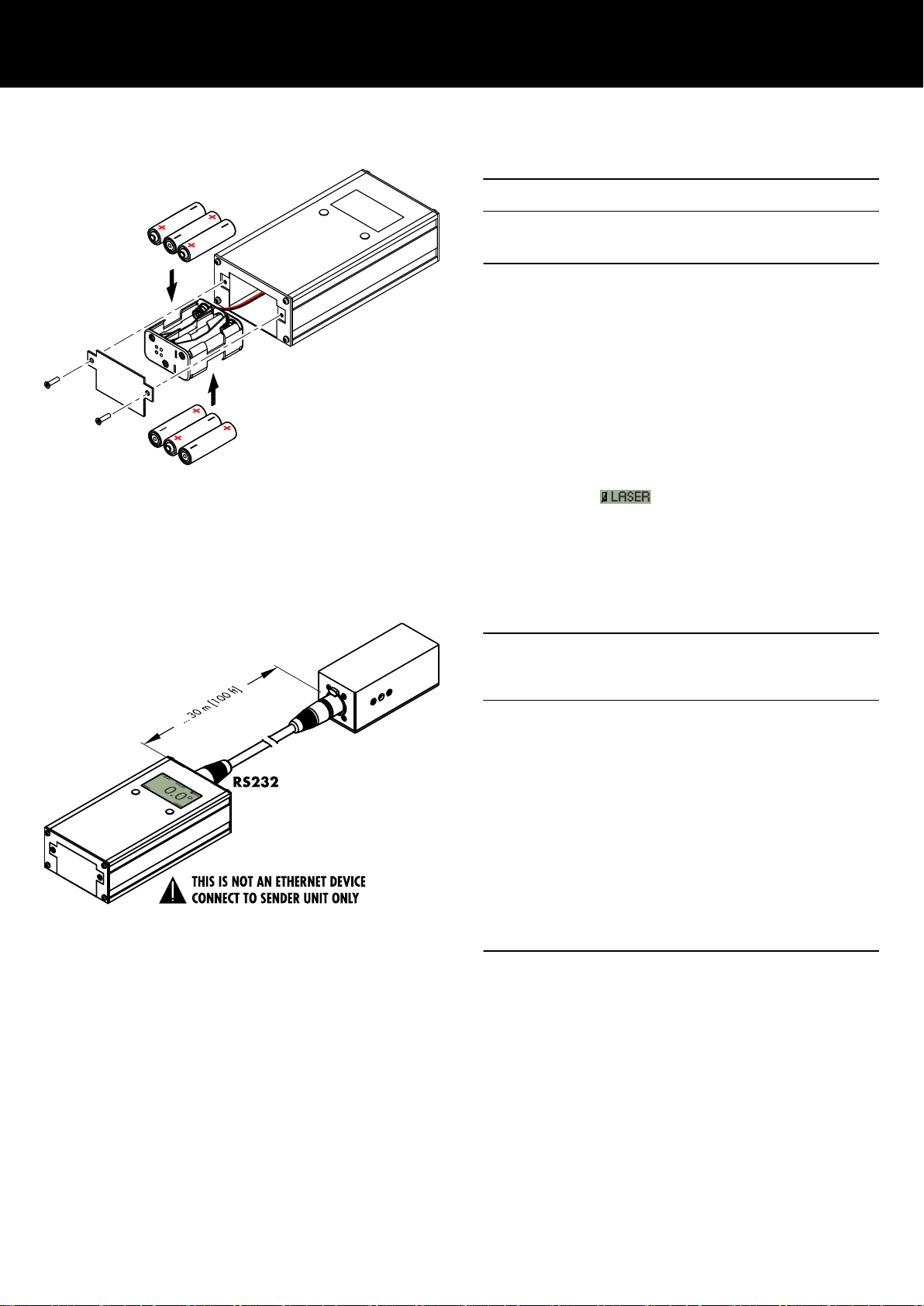
3.1 Installing the batteries
NOTICE!
To power the ArraySight inclinometer system, professional high
power Alkaline batteries (6 x AA - 1.5 VDC) must be used.
1. To insert and remove the batteries, undo the two M3 screws
on the end of the meter unit and slide out the battery holder.
↳
Observe the correct polarity.
2. Reinsert the battery holder and redo the screws.
To conserve battery life, the meter unit is set to power down after
one minute of inactivity by factory default. This can be adjusted in
the Þ «Auto power» menu.
Note: Once the battery voltage drops below 7.75 V
(approx. 24%) , the laser unit will be switched off and is no
more accessible. The battery icon on the display will be
crossed out Þ
.
However, the meter unit remains operating and angle
measurements are still possible.
3.2 Connecting the units
NOTICE!
Potential risk of malfunction and/or damaging to
components!
The meter unit is not an Ethernet device!
DO NOT connect the meter unit to any Ethernet port or device
such as Ethernet switches.
The meter unit is equipped with an RS232 interface and provides
the power supply and communication for the direct connection of a
single sender unit for read out.
Connect the sender unit to the meter unit using the enclosed,
shielded CAT5e 1:1 cable with etherCON connectors.
For this purpose, the meter and sender units are equipped with
corresponding etherCON connector sockets.
Cable lengths of up to 30 m (100 ft) are allowed.
DO NOT use any cables other than specified above.
d&b ArraySight Manual 1.7 en8
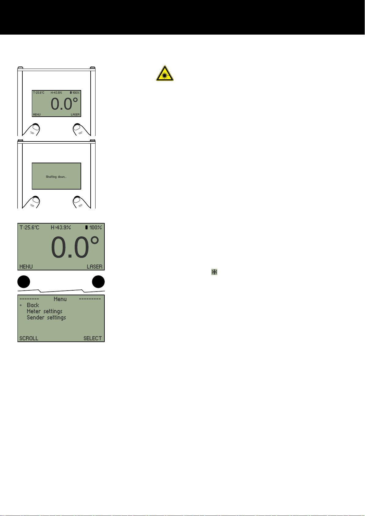
3.3 Switching on/switching off Please observe the "Safety precautions when using
laser equipment!"
1. To switch on the meter unit, hold down both buttons below the
screen.
↳
The menu screen will illuminate and initially display the d&b
logo. The unit will then switch to the «Home» screen and
display the current angle readout.
2. Release both buttons.
3. To power down the meter unit (and the connected sender
unit), proceed in the same manner until the «Shutting down»
message is displayed.
3.4 User interface of the meter unit
The meter unit features a detailed graphical display with an
intuitive on-screen menu system.
Navigation through the menus is by two buttons below the display.
Within the main menu and the submenus, the left-hand button is
generally used to scroll down through the menu items
Þ «SCROLL». The corresponding menu items are marked by an
asterisk (
).
The right-hand button is used to select a function Þ «SELECT».
Apart from that, the buttons have different functions within the
various submenus. The current function is always indicated above
each button (e.g. «BACK», SET, «CANCEL», «INC»...)
The display is backlit for viewing in all light conditions.
d&b ArraySight Manual 1.7 en 9

3.5 The menu structure
3.5.1 Home screen
The Home screen is split into three sections:
Header Indicates the actual onsite temperature («T») and
humidity («H») as well as the battery status in
gaphic form and as a percentage value.
Read out The current angle readout in degrees, relative to the
last calibration of the unit.
Footer From the Home screen, the following functions are
accessible:
MENU Left-hand button to enter the Þ Main menu
«Menu».
LASER Please observe the "Safety precautions
when using laser equipment"!
The right-hand button provides access to the laser
function with the following options:
On Þ Flash mode Þ Off
Please also refer to Þ Chapter 5.4 "Using the
laser" on page 17.
3.5.2 Main menu «Menu» The main menu screen provides direct access to the:
Þ Meter settings
Þ Sender settings
3.5.3 Meter settings
History
Displays the last four readings of the inclinometer.
The readings are saved every time the unit is
powered off, or when the sender unit is
disconnected.
Auto
power
Temp. unit
Defines the auto power-off timer between 1 min.
(default), 2 min. and 5 min.
Defines the temperature units.
°C/°F
Version Displays the currently installed firmware version
of both the meter and the sender units.
If the sender unit is not connected, «Offline» will
be displayed instead.
d&b ArraySight Manual 1.7 en10

3.5.4 Sender settings
IP
settings
Defines the required IP settings such as the IP
address Þ «IP», the Subnet Þ «SN», the Gateway
Þ «GW» and the IP mode Þ «Mode».
By factory default, the IP mode is set to «Auto» and
is recommended for a network with a DHCP server
present Þ DHCP+LL (Link Local).
The IP mode can be set to «Manual» if required.
RemoteIDDefines the required «Remote ID» settings in
connection with d&b R1.
The «Remote ID» menu comprises two items, the
«Subnet» and the «Device ID».
Within an d&b OCA network, up to 100 subnets
can be defined (values 0 to 99).
Using the two digit Device ID for each subnet, you
can define a total of 63 devices (values 1 to 63).
Reset
angle
(zeroing)
Saves an angle offset in the sender unit for relative
measurements. When performed, the meter displays
zero, when the sender unit is in its current position.
The reset angle function is also used to ensure that
the sender unit is correctly aligned to the flying
frame (refer to Þ Chapter 4.1 "Resetting the angle
(zeroing)" on page 13).
Calibrate By factory default, the sender unit is already
calibrated.
However, for maintenance reasons it might be
necessary to re-calibrate the sender unit’s
accelerometer.
For this purpose, selecting «Calibrate» starts the
calibration procedure for the connected sender unit
as described in Þ Chapter 7.3 "Calibrating the
accelerometer" on page 20.
d&b ArraySight Manual 1.7 en 11

3.5.4.1 Editing IP and Remote ID settings
Editing the IP and the Remote ID settings is performed in the same
manner.
To edit the IP settings, proceed as follows:
1. Ensure the sender unit is connected.
↳
If the connection of the sender unit has been accidently
interrupted, this will be detected by the meter unit within 5
seconds.
The meter unit will then switch to the «Home» screen and a
corresponding message will be issued.
The «LASER» button and the sender settings menu will no
longer be accessible.
After the interruption has been resolved, the meter unit will
return to the Home screen.
The «LASER» button and the sender settings menu will
become accessible again.
2. Within the «Sender settings» menu, select the «IP settings» item
to enter the «IP settings» menu.
3. Scroll to the desired item (e.g. IP) and press the «SELECT»
button.
↳
The «Set IP» menu opens and the first digit is flashing.
4. Use the «SCROLL» button to move through the digits. When a
digit is marked, it starts flashing.
Use the «INC» button to increment the selected digit by one.
5. Once the last digit is selected, the left-hand button changes
from «SCROLL» to «SET».
6. Press the button to confirm your changes.
↳
The meter unit switches back to the «IP settings» menu.
If no changes have been made, the meter unit switches
directly back to the «IP settings» menu as soon as you scroll
to the last digit.
d&b ArraySight Manual 1.7 en12

4 Resetting the angle (zeroing) and laser alignment
4.1 Resetting the angle (zeroing)
Preparation
1. With the flying frame resting on a solid, stable and flat
surface, check the sender unit is correctly aligned.
2. Place a good quality spirit level, or calibrated digital level on
the top edge of the flying frame as shown in the graphic
opposite. You need to check that the top of the flying frame is
truly horizontally [x] and vertically [z] leveled.
3. Fix the flying frame at the front or rear as required to ensure
that it is perfectly aligned.
↳
Once this is achieved, you can reset the angle of the
sender unit as follows:
Resetting the angle
1. Switch on the connected meter unit and confirm that the initial
display is showing 0.0°.
2. Select "«MENU» Þ «Sender settings» Þ «Reset angle»".
3. Press «SET» to confirm the reset.
↳
The angle displayed, will be set to zero (0.0°) and the
offset value is stored in the sender unit, even when it is
disconnected from the meter unit.
Note: The angle needs to be reset for each sender unit in
use. If you have sender units attached to a left and right array,
when you plug the second sender unit in, you will need to
reset this to zero, but if subsequently you reconnect the meter
unit to the first sender unit at this location, the offset value
stored in the sender unit is still valid.
d&b ArraySight Manual 1.7 en 13

4.2 Aligning the laser Take precautions to prevent anyone from looking
directly into the laser beam.
Wear appropriate eye protection.
In normal use, the initial factory setup can be relied on, but if the
unit is dropped or exposed to extreme temperatures, the laser may
be realigned.
Correct alignment of the laser means the beam is emitted precisely
on a central axis in relation to the case of the sender unit in both,
the horizontal and vertical orientations.
Note: It is recommended that you label the sender unit with
the date and name of the person conducting the work so a
record of the laser alignment is maintained.
Small errors in alignment will multiply the further the laser is
projected. It is therefore important to check the laser alignment
from time to time and adjust it where necessary.
This procedure should be carried out at base in a workshop,
not on site.
It is essential for the sender unit to be accurately in position during
the alignment procedure, both vertically and horizontally. To
achieve this, place the Flying frame on a solid, stable and flat
surface with a known level surface as described in the previous
section (Þ Chapter 4.1 "Resetting the angle (zeroing)"
on page 13).
1. Connect the sender unit to the meter unit so the laser can be
operated.
2. You also require a vertical surface to project the laser onto,
positioned at a distance of 10 m (33 ft) from the sender unit.
Alignment Procedure
Tools required: Torx wrench #T10
1. Switch on the laser and check where the laser dot falls on the
vertical target surface.
2. Adjust the alignment of the laser using the three M3 machine
screws around the circumference of the laser bezel.
↳
The adjustment is quite sensitive, so make small adjustments
to each in turn and make sure that any of the screws are
not tightened completely.
The required accuracy is ± 5 mm (± 0.2" hor./vert.) which
leads to a maximum deviation of 10 cm/100 m
(3.94"/328 ft).
3. Adjust the screws until the laser dot aligns precisely.
4. Switch the laser off and disconnect the sender unit.
d&b ArraySight Manual 1.7 en14

5. Once alignment is complete, place a drop of thread-locking
fluid on each of the screw heads to prevent loosening.
d&b ArraySight Manual 1.7 en 15

5 Using the system
5.1 Measuring the angle
Once the array has been hoisted to its working height, ArraySight
uses intelligent interpolating algorithms to determine the resting
point of the array, while it is still moving after motor adjustment.
This is important because it means you can make accurate
measurements without waiting for the system to come to a
complete rest after adjustment. It typically takes around three
periods of oscillation, or pendulum swings of the array for the
sender unit to achieve an accurate measurement of the angle.
As a guideline, the angle display has the following accuracy:
Cycles Accuracy
1 period of swing ±1.0
2 periods of swing ±0.5
3 periods of swing ±0.1
Clearly, the measurement cannot be relied upon when the motor
hoists are actually in operation. Once the hoist(s) have stopped,
the meter unit quickly resolves the measurement. A usable value for
the resting angle is normally displayed within a few seconds.
5.2 Measurement limits
ArraySight has a usable range of ±45° with full accuracy. The
sender unit sensor is capable of measuring angles up to ±90°, but
with reduced accuracy of ±1°. The additional range is available to
you to use, but it should be used with caution.
5.3 Adjusting angles using relative values
The angle of the flying frame can be re-adjusted to a new angle,
relative to its original angle. This is achieved by resetting the
sender unit to zero while in situ at the original angle as described
in Þ Chapter 4.1 "Resetting the angle (zeroing)" on page 13. The
array can then be tilted on the hoists, reading the value off the
adjustment on the meter unit, relative to the original position.
Note: When the sender unit has been reset in this way, its
true horizontal position will no longer display 0.00°. This is
why we recommend checking the horizontal position at the
start of each sender unit installation.
d&b ArraySight Manual 1.7 en16

5.4 Using the laser Take precautions to prevent anyone from looking
directly into the laser beam.
Wear appropriate eye protection.
The sender unit features a powerful laser to assist angle
adjustment. The laser is used to confirm that the upper margin of
the PA system dispersion reaches the design target - for example
the seating at the rear of an auditorium.
1. On the «Home» screen, «LASER» is displayed at the bottom
right.
2. Press the right-hand button once to switch the laser on.
↳
Pressing the button a second time will put the laser into
flashing mode, which can be useful for locating the beam in
a bright location. Pressing the button a third time turns the
laser off.
The on/off and flashing mode statuses are indicated by a
corresponding permanent or flashing laser icon to the left
of the «LASER» item Þ
.
5.5 Application example
To take an example: ArrayCalc indicates a frame angle of –3.6°
from vertical.
1. Using ArraySight to measure this angle, you raise the first
array to its operating height and then check the meter unit
screen.
2. The figures displayed settle as the meter compensates for the
swing of the array. If the settled display shows +0.5°, you
then use the hoists to lift the rear or lower the front of the
array. Make small adjustments and allow the meter unit to
calculate the new angle. Continue to make adjustments until
you achieve the angle of –3.6°.
3. Once the first array is complete, disconnect the meter unit from
the first sender unit and reconnect it to the sender unit of the
second array.
4. Repeat the procedure, starting with resetting the angle to zero
for the second sender unit. Raise the second array, check the
angle and adjust the angle as necessary.
5. If subsequent re-adjustment of the first array is required the
meter unit can be re-connected to the first sender unit and the
correct offset will be recalled.
d&b ArraySight Manual 1.7 en 17

6 OCA integration (Ethernet)
NOTICE!
Potential risk of malfunction and/or damage to the
device!
Only use POE injector devices and/or switches which comply with
the POE standards IEEE802.3at or IEEE802.3af.
DO NOT use passive injector devices or switches.
The data transmission rate is fixed @ 100 Mbit/Half-duplex.
Therefore ensure that you use compatible switches.
In standard operation, the sender unit is directly connected to the
meter unit which provides power supply and communication via its
RS232 interface.
However, the sender unit also supports the d&b OCA/AES70
protocol and therefore directly integrates into the d&b workflow in
connection with the d&b ArrayCalc simulation and R1 Remote
control software. This allows multiple sender units to be read out
within R1.
By factory default, the sender unit comes with the following
ethernet and remote settings:
IP mode:
IP address:
Subnet:
Gateway:
Remote ID:
Auto Þ DHCP+LL (Link Local)
192.168.0.111
255.255.255.0
192.168.0.1
0.01
d&b ArraySight Manual 1.7 en18
7 Maintenance and care
7.1 Cleaning
During normal operation, the units provide maintenance-free
service.
If the units require cleaning ...:
▪ Use a soft cloth only.
▪ Do not use any solvent cleaners.
▪ Do not spray directly on the LC display or laser.
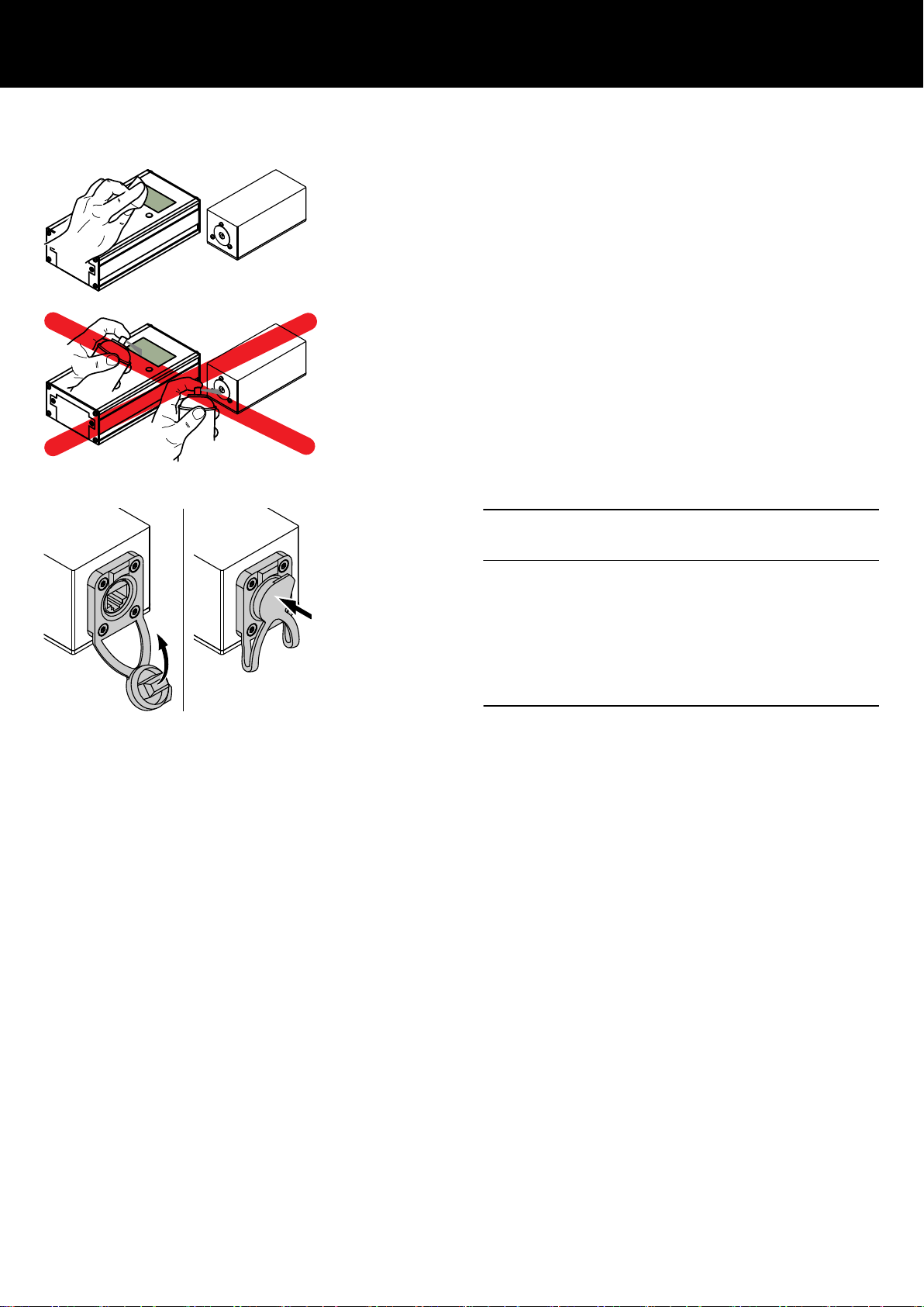
7.2 etherCON connector socket protection
NOTICE!
Possible risk of damage to the device!
Always make sure the dust cap of the etherCON connector socket
is properly attached (closed) during transport or when it is not in
use, as shown in the graphic opposite.
This prevents the sender unit from damage due to:
▪ Ingression of moisture or liquids (e.g. water from rain) through
the etherCON connector socket,
▪ corrosion of the connector socket's spring contacts.
d&b ArraySight Manual 1.7 en 19
7.3 Calibrating the accelerometer ENSURE the laser is switched off throughout this
procedure.
The ArraySight sender units are calibrated in the factory using
precision calibration jigs. If this process is attempted without a level
surface and a true 90° angle, then calibration information could
be incorrect. Only attempt this process if you have the appropriate
facilities to ensure accuracy.
Calibration is performed using gravity as a reference.
Note: If you are interrupted during any of the following steps,
or the display shows anything other than indicated, you will
need to start the procedure again. Errors can occur if the unit
'times out' or if a button is inadvertently pressed twice.
The calibration procedure can be canceled at any time by
pressing the left-hand «CANCEL» button.
1. Place the sender on a known level surface with a block or side
fence positioned at exactly 90°, so the unit can be registered
accurately both vertically and horizontally.
2. Connect the sender unit to the meter unit and power it up.
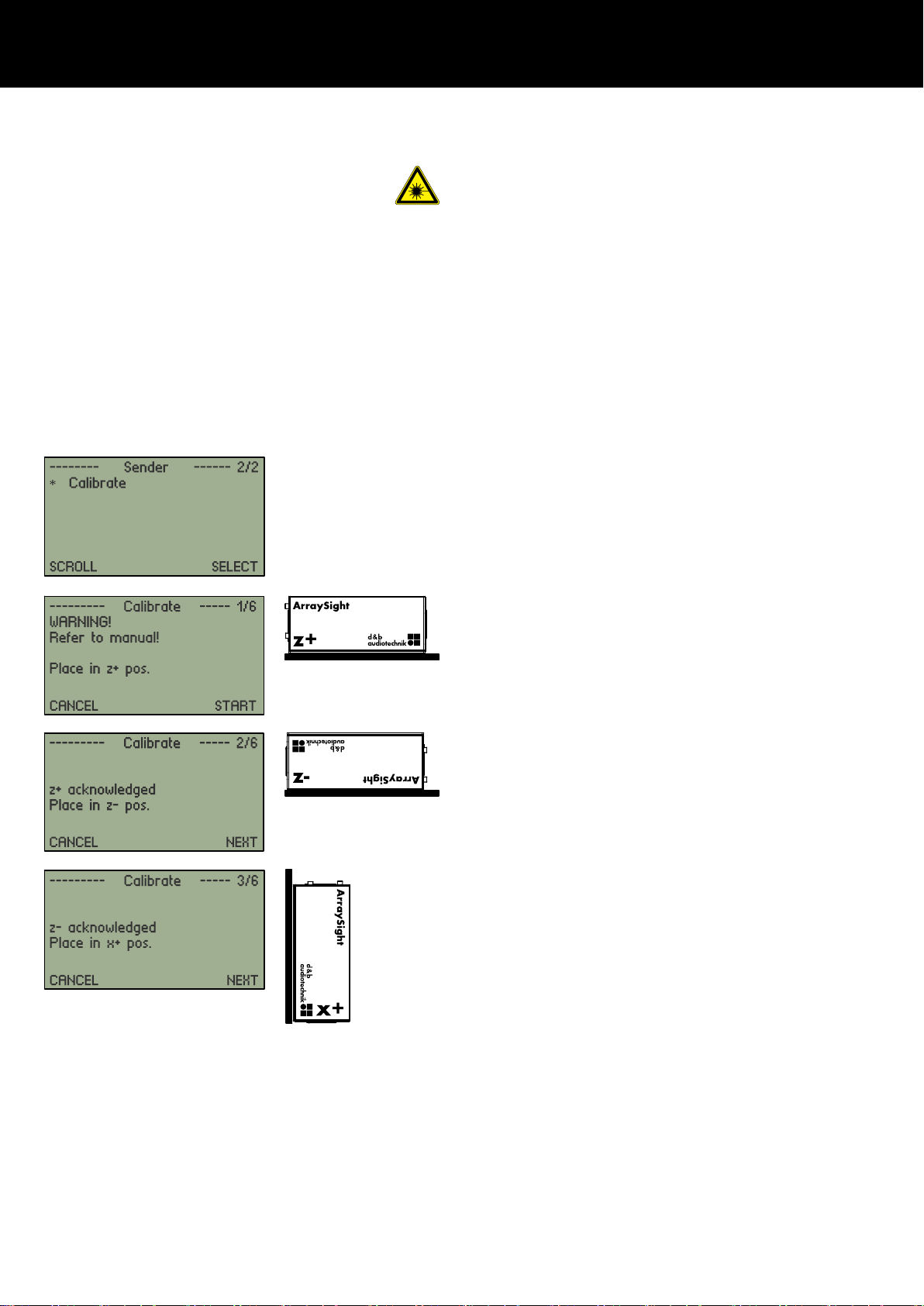
3. Select "«MENU» Þ «Sender settings» Þ «Calibrate»".
You’ll then need to follow a six step procedure:
1. First, the meter screen will prompt you to place the sender in
the z+ position.
z+ is the sender unit’s "normal" orientation, sat flat on the
table top.
Select «START»…
2. When «z+ acknowledged » is displayed, place the unit in the
z– position, i.e. upside down on the table top, so the base of
the unit is facing upwards.
Select «NEXT»…
3. When «z– acknowledged» is displayed, you are next
prompted to place the unit in the x+ position.
In the x+ position, the unit points upwards, with the laser
aperture at the top. This requires holding the unit with the base
against a vertical surface.
Select «NEXT»…
d&b ArraySight Manual 1.7 en20

4. When «x+ acknowledged» is displayed, place the unit in the
x– position by turning the unit 180 degrees.
The laser aperture should now point downwards and the top
of the unit should rest against the vertical surface.
Select «NEXT»…
5. When «x– acknowledged» is displayed, you are next
prompted to place the unit in the y+ position.
Turn the unit on its side, in a clockwise direction so when the
unit is viewed from the front, the brass screw nearest the top
surface is now at 9 o’clock, and the base of the unit rests
against the side fence. This is y+.
Select «NEXT»…
6. When «y+ acknowledged» is displayed, you are prompted to
place the unit in the y– position.
Turn the unit through 180 degrees.
The brass screw has moved from 9 o’clock to 3 o’clock.
Select «NEXT»…
When «y– acknowledged» is displayed on the screen, the sender
unit will process the measurements and calibration will be
complete. This data is stored in the non-volatile EEPROM in the
sender unit.
When «y– acknowledged» is displayed on the screen, the sender
unit will process the measurements and calibration will be
complete. This data is stored in the non-volatile EEPROM in the
sender unit.
Correctly calibrated, the sender unit will provide accurate angle
measurements in all orientations.
d&b ArraySight Manual 1.7 en 21

8 Manufacturer's declarations
8.1 EU declaration of conformity (CE symbol)
This declaration applies to:
d&b Z5710 ArraySight set
Including:
▪ Z5711 ArraySight sender unit
▪ Z5712 ArraySight meter unit
Provided they correspond to the original technical version and
have not been subject to any later design or electro mechanical
modifications.
▪ General Product Safety Directive 2001/95/EC
rd
▪ IEC 61010-1:2010 (3
Edition) Safety requirements for
electrical measurement, control and laboratory use.
▪ IEC/EN 60825-1:2014 Safety of laser products.
▪ IEC 60529/A2:2013 Degrees of protection provided by
enclosure (IP code).
▪ Electromagnetic Compatibility (EMC) Directive) 2014/30/EU
▪ EN61326-2-1:2013 (EN 61326-1:2013) & FCC CFR 47
parts 15, 107 & 15.109 and ICES-003 Issue 6 (EMC).
▪ Restriction of Hazardous Substances 2011/65/EU
We herewith declare that said products are in conformity with the
provisions of the respective EC directives and Standards including
all applicable amendments.
8.2 WEEE Declaration (Disposal)
Electrical and electronic equipment must be disposed of separately
from normal waste at the end of its operational lifetime.
Please dispose of this product according to the respective national
regulations or contractual agreements. If there are any further
questions concerning the disposal of this product, please contact
d&b audiotechnik.
d&b ArraySight Manual 1.7 en22

FreeRTOS
Permission is hereby granted, free of
charge, to any person obtaining a copy of
this software and associated
ocumentation files (the "Software"), to
deal in the Software without restriction,
including without limitation the rights
to use, copy, modify, merge, publish,
distribute, sublicense, and/or sell
copies of the Software, and to permit
persons to whom the Software is furnished
to do so, subject to the following
conditions:
The above copyright notice and this
permission notice shall be included in
all copies or substantial portions of the
Software.
8.3 Licenses and Credits
This product uses a number of third-party libraries to provide
certain features. These libraries are supplied along with the
product.
THE SOFTWARE IS PROVIDED "AS IS", WITHOUT
WARRANTY OF ANY KIND, EXPRESS OR IMPLIED,
INCLUDING BUT NOT LIMITED TO THE
WARRANTIES OF MERCHANTABILITY, FITNESS
FOR A PARTICULAR PURPOSE AND
NONINFRINGEMENT. IN NO EVENT SHALL THE
AUTHORS OR COPYRIGHT HOLDERS BE LIABLE
FOR ANY CLAIM, DAMAGES OR OTHER
LIABILITY, WHETHER IN AN ACTION OF
CONTRACT, TORT OR OTHERWISE, ARISING
FROM, OUT OF OR IN CONNECTION WITH THE
SOFTWARE OR THE USE OR OTHER DEALINGS IN
THE SOFTWARE.
lwIP
lwIP is licensed under the BSD license:
Copyright (c) 2001-2004 Swedish Institute
of Computer Science. All rights reserved.
1. Redistributions of source code must
retain the above copyright notice,
this list of conditions and the following
disclaimer.
2. Redistributions in binary form must
reproduce the above copyright notice,
this list of conditions and the following
disclaimer in the documentation
and/or other materials provided with the
distribution.
3. The name of the author may not be used
to endorse or promote products
derived from this software without
specific prior written permission.
THIS SOFTWARE IS PROVIDED BY THE AUTHOR
AS IS AND ANY EXPRESS OR IMPLIED
WARRANTIES, INCLUDING, BUT NOT LIMITED
TO, THE IMPLIED WARRANTIES OF
MERCHANTABILITY AND FITNESS FOR A
PARTICULAR PURPOSE ARE DISCLAIMED. IN NO
EVENT SHALL THE AUTHOR BE LIABLE FOR ANY
DIRECT, INDIRECT, INCIDENTAL, SPECIAL,
EXEMPLARY, OR CONSEQUENTIAL DAMAGES
(INCLUDING, BUT NOT LIMITED TO,
PROCUREMENT OF SUBSTITUTE GOODS OR
SERVICES; LOSS OF USE, DATA, OR PROFITS;
OR BUSINESS INTERRUPTION) HOWEVER CAUSED
AND ON ANY THEORY OF LIABILITY, WHETHER
IN CONTRACT, STRICT LIABILITY, OR TORT
(INCLUDING NEGLIGENCE OR OTHERWISE)
ARISING IN ANY WAY OUT OF THE USE OF THIS
SOFTWARE, EVEN IF ADVISED OF THE
POSSIBILITY OF SUCH DAMAGE.
d&b ArraySight Manual 1.7 en 23

edeca/Electronics graphics library
Copyright (c) 2010-2015, David Cannings
All rights reserved.
Redistribution and use in source and
binary forms, with or without
modification, are permitted provided that
the following conditions are met:
* Redistributions of source code must
retain the above copyright notice, this
list of conditions and the following
disclaimer.
* Redistributions in binary form must
reproduce the above copyright notice,
this list of conditions and the following
disclaimer in the documentation and/or
other materials provided with the
distribution.
* Neither the name of the author nor the
names of contributors may be used to
endorse or promote products derived from
this software without specific prior
written permission.
THIS SOFTWARE IS PROVIDED BY THE
COPYRIGHT HOLDERS AND CONTRIBUTORS "AS
IS" AND ANY EXPRESS OR IMPLIED
WARRANTIES, INCLUDING, BUT NOT LIMITED
TO, THE IMPLIED WARRANTIES OF
MERCHANTABILITY AND FITNESS FOR A
PARTICULAR PURPOSE ARE DISCLAIMED.
IN NO EVENT SHALL THE COPYRIGHT HOLDER OR
CONTRIBUTORS BE LIABLE FOR ANY DIRECT,
INDIRECT, INCIDENTAL, SPECIAL, EXEMPLARY,
OR CONSEQUENTIAL DAMAGES (INCLUDING, BUT
NOT LIMITED TO, PROCUREMENT OF SUBSTITUTE
GOODS OR SERVICES; LOSS OF USE, DATA, OR
PROFITS; OR BUSINESS INTERRUPTION)
HOWEVER CAUSED AND ON ANY THEORY OF
LIABILITY, WHETHER IN CONTRACT, STRICT
LIABILITY, OR TORT (INCLUDING NEGLIGENCE
OR OTHERWISE) ARISING IN ANY WAY OUT OF
THE USE OF THIS SOFTWARE, EVEN IF ADVISED
OF THE POSSIBILITY OF SUCH DAMAGE.
d&b ArraySight Manual 1.7 en24
9 Appendix
9.1 Z5710.xxx d&b ArraySight sets
In connection with d&b flying frames other than the SL-Series flying
frames, d&b also provides additional ArraySight sets including
dedicated flying frame adapter to allow the d&b ArraySight
sender unit to be mounted to the corresponding flying frame.
The following sets are covered by this manual
(Mounting instructions):
▪ Z5710.001: d&b ArraySight set J-Series
▪ Z5710.002: d&b ArraySight set V-Series
Apart from any other items, each ArraySight set includes the
mechanical components (flying frame adapter) for two flying
frames.
Please verify the shipment for completeness and proper condition
of the items.
Tools required
▪ Torx screw driver T20
▪ Torx screw driver T25
▪ Socket wrench SW8
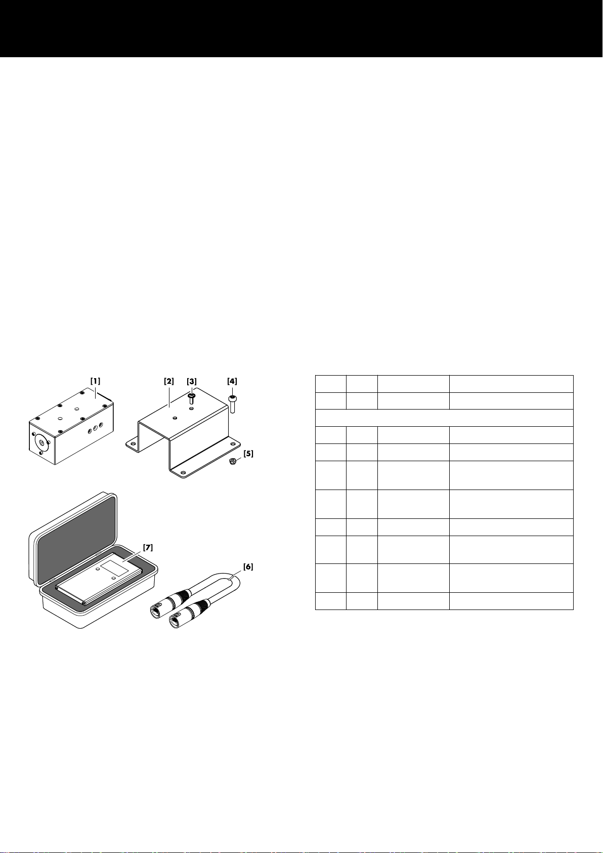
9.1.1 Z5710.001 Mounting instructions
Scope of supply
Pos.
Qty. d&b Code Description
1 Z5710.001 d&b ArraySight set J-Series
Including:
[1] 2 Z5711 ArraySight sender unit
[2] 2 J Flying frame adapter
[3] 4 Panhead screw (Torx T20)
M4 x 12
[4] 8 Panhead screw (Torx T25)
M5 x 18
[5] 8 Self securing nut M5
[6] 2 K6006.200.00 Shielded CAT5e 1:1 cable,
30 m (100 ft)
[7] 1 Z5712 ArraySight meter unit
within transport case
1 D2735.EN .01 ArraySight Manual
d&b ArraySight Manual 1.7 en 25

Assembly
1. First attach the ArraySight sender unit [1] to the flying frame
adapter [2].
2. Fix the sender unit with the two panhead screws (M4 x 12)
[3].
3. As the sender unit assembly is mounted from the bottom of the
J flying frame, turn frame by 180°.
4. Position the frame onto an appropriate and flat surface.
5. Attach the sender unit assembly to the mounting plate of the
frame with the laser unit facing towards the front of the frame.
6. Fix the sender unit assembly using the four panhead screws
(M5 x 18) [4] and the self securing nuts (M5) [5].
7. Recheck your work and ensure all screws are properly
tightened.
9.1.2 Z5710.002 Mounting instructions
Scope of supply
Pos.
Qty. d&b Code Description
1 Z5710.002 d&b ArraySight set V-Series
Including:
[1] 2 Z5711 ArraySight sender unit
[2] 2 V Flying frame adapter
[3] 12 Panhead screw (Torx T20)
M4 x 12
[4] 2 K6006.200.00 Shielded CAT5e 1:1 cable,
30 m (100 ft)
[5] 1 Z5712 ArraySight meter unit
within transport case
1 D2735.EN .01 ArraySight Manual
d&b ArraySight Manual 1.7 en26

Assembly
1. First attach the ArraySight sender unit [1] to the flying frame
adapter [2].
2. Fix the sender unit using two panhead screws (M4 x 12) [3].
3. Position the V flying frame onto an appropriate and flat
surface.
4. Attach the sender unit assembly to the mounting plate of the
frame with the laser unit facing towards the front of the frame.
5. Fix the sender unit assembly using four panhead screws
(M4 x 12) [3].
6. Recheck your work and ensure all screws are properly
tightened.
d&b ArraySight Manual 1.7 en 27

D2735.EN .01, 04/2019 © d&b audiotechnik GmbH
www.dbaudio.com
 Loading...