

d&b audiotechnik ArraySight, ArraySight Z5710 User Manual
ArraySight
A
Manual 1.7 en

General information
ArraySight Manual
Version: 1.7 en, 04/2019, D2735.EN .01
Copyright © 2019 by d&b audiotechnik GmbH; all rights
reserved.
Keep this document with the product or in a safe place
so that it is available for future reference.
We recommend you to regularly check the d&b website for the
latest version of this document.
When reselling this product, hand over this document to the new
owner.
If you supply d&b products, please draw the attention of your
customers to this document. Enclose the relevant documents with
the systems. If you require additional documents for this purpose,
you can order them from d&b.
d&b audiotechnik GmbH
Eugen-Adolff-Straße 134, D-71522 Backnang, Germany
T +49-7191-9669-0, F +49-7191-95 00 00
Safety precautions when using laser equipment
WARNING!
Potential risk of damage to the eyes.
Laser class 3R, 532 nm, <5 mW:
Do not suppress eye-closure reflex.
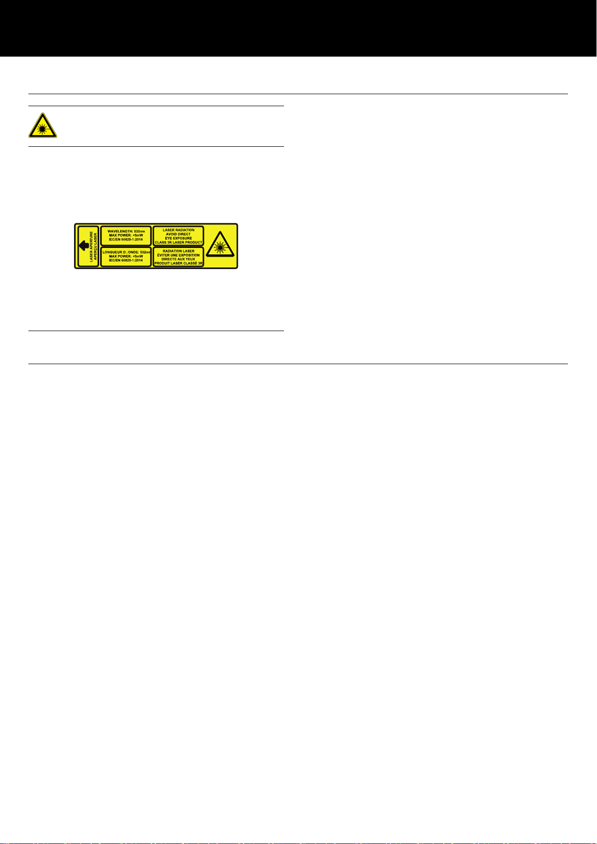
The d&b ArraySight sender unit is shipped with the following label
affixed to the top surface. Do not remove this label under any
circumstances.
The high brightness laser of the sender unit requires additional
safety considerations.
Please give careful attention to the following safety warnings
before using the d&b ArraySight inclinometer system.
NEVER look directly into the laser, even when it is switched off, as
someone may activate it without warning you.
WARN others in the venue that you are going to use a laser and
move them away from the target area before activating a laser.
ENSURE that others do not enter the target area of the laser while
it is in use.
ENSURE that the meter unit is to hand at all times so that the
beam can be switched off immediately if necessary.
ALWAYS use the laser for the minimum amount of time possible.
You can carry out most of the alignment procedure with the laser
turned off.
Disconnect the cable from the meter unit once the measurements
had been made.
ALWAYS ensure that the meter unit is disconnected when the
public have access to the venue.
NEVER leave the laser turned on while unattended.
NEVER use the laser in any other application than it is intended
for.
Operational safety
The d&b ArraySight inclinometer system is an integrated part of the
d&b rigging system and should be regarded with the same respect
as any other rigging component.
The sender unit must be safely mounted to the corresponding
Flying frame when used above 2 m (6.6 ft) from ground level using
the enclosed fixing screws.
DO NOT fix the sender unit with tape or velcro.
When making adjustments to the array with motor hoists, watch the
hoist - not the meter unit! Check the measurement only when the
hoist has finished moving.
When using the meter unit, be aware of other rigging operations
taking place around you. Always follow the appropriate safety
procedures (including wearing the appropriate personal protective
equipment).
The sender unit is weather/water resistant (IP54), enabling it to
withstand dust ingress and rain, although the limited ingress of
water may be possible. It is therefore advisable to take account of
prevailing weather and environmental conditions and take
precautions to protect the sender unit.
As with any rigging components, regular safety inspections are
obligatory.
d&b ArraySight Manual 1.7 en 3

Contents
1 d&b ArraySight..................................................................... 5
1.1 Scope of supply.......................................................................... 5
1.2 Intended use................................................................................ 5
2 Technical specifications...................................................... 7
3 Startup...................................................................................... 8
3.1 Installing the batteries................................................................. 8
3.2 Connecting the units................................................................... 8
3.3 Switching on/switching off......................................................... 9
3.4 User interface of the meter unit.................................................. 9
3.5 The menu structure.................................................................... 10
3.5.1 Home screen......................................................................... 10
3.5.2 Main menu «Menu»............................................................. 10
3.5.3 Meter settings........................................................................ 10
3.5.4 Sender settings...................................................................... 11
3.5.4.1 Editing IP and Remote ID settings..................................... 12
4 Resetting the angle (zeroing) and laser
alignment.............................................................................. 13
4.1 Resetting the angle (zeroing)................................................... 13
4.2 Aligning the laser..................................................................... 14
5 Using the system................................................................ 16
5.1 Measuring the angle................................................................ 16
5.2 Measurement limits.................................................................. 16
5.3 Adjusting angles using relative values.................................... 16
5.4 Using the laser.......................................................................... 17
5.5 Application example................................................................ 17
6 OCA integration (Ethernet)............................................ 18
7 Maintenance and care.................................................... 19
7.1 Cleaning................................................................................... 19
7.2 etherCON connector socket protection.................................. 19
7.3 Calibrating the accelerometer................................................. 20
8 Manufacturer's declarations......................................... 22
8.1 EU declaration of conformity (CE symbol)............................. 22
8.2 WEEE Declaration (Disposal).................................................. 22
8.3 Licenses and Credits ................................................................ 23
9 Appendix.............................................................................. 25
9.1 Z5710.xxx d&b ArraySight sets............................................. 25
9.1.1 Z5710.001 Mounting instructions...................................... 25
9.1.2 Z5710.002 Mounting instructions...................................... 26
d&b ArraySight Manual 1.7 en4
1 d&b ArraySight
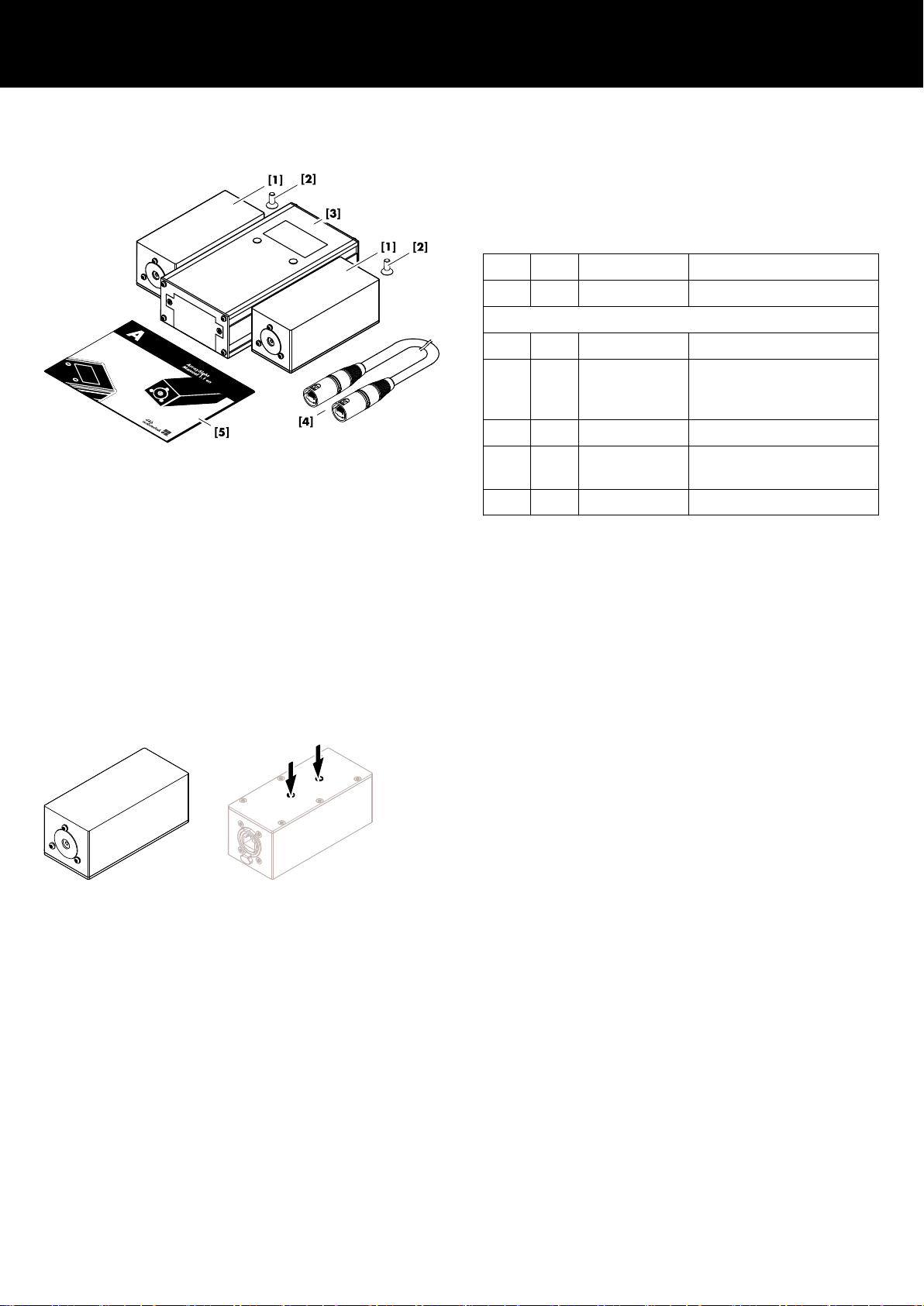
1.1 Scope of supply
Before setting up the system, please verify the shipment for
completeness and proper condition of the items.
If there is any sign of obvious damage, do not operate the units
and contact your local dealer from whom you received the system.
Pos. Qty. d&b Code Description
1 Z5710 d&b ArraySight set
Including:
[1] 2 Z5711 ArraySight sender unit
[2] 2 2 x Fixing screws for each
sender unit
(Torx T20, M4 x 14 mm).
[3] 1 Z5712 ArraySight meter unit
[4] 2 K6006.200.00 Shielded CAT5e 1:1 cable,
30 m (100 ft)
[5] 1 D2735.EN .01 ArraySight Manual
1.2 Intended use
The d&b ArraySight laser inclinometer system is intended to
vertically aim an entire array in its operating position. It provides
precision angle measurement over a wide measuring range of ±90
degrees. The sender unit uses a 3-axis MEMS accelerometer for
data acquisition. This provides accurate tilt sensing over one axis,
even when the unit is tilted on another axis. Accurate angle
measurements can be achieved, resolved to ±0.1 degrees on the
display of the meter unit.
The compact sender unit is housed in a weather resistant enclosure.
It utilizes an ultra bright green laser to provide a visible indication
for aiming the array, with a flashing mode to help locate the beam
in bright surroundings.
The sender unit can be attached to dedicated d&b Flying frames.
For this purpose, the sender unit has two threaded inserts on its
base and comes with dedicated fixing screws (Torx T20, M4 x
14 mm).
Easy calibration
Multiple sender units can be used with one meter unit. Calibration
information is stored in the sender unit using non-volatile memory,
so it remains accurate after the meter unit is disconnected. Sender
units can be reset on the fly to any angle within range, allowing
adjustment of system elevation to be made in absolute values if
required. Calibration is carried out via the meter unit’s onscreen
menu, without the need to dismantle units or use precision
hardware.
Relative angle measurement
The meter unit’s zero function means relative angle measurements
can be made via the on-screen menu and the last four readings are
stored for easy recall.
d&b ArraySight Manual 1.7 en 5

Intelligent interpolative measurement
It is possible to make accurate measurements, even before the
system has reached its final resting angle after hoist adjustment.
The meter unit automatically displays the final resting angle within
three periods of oscillation. This reduces installation time, with no
need to wait until the system comes to rest after each angle
adjustment.
Temperature and humidity measurement
In addition, the sender unit incorporates a thermo- and hygrometer
(sensor) to derive the actual onsite temperature and humidity.
Note: The sensor is calibrated by factory default and requires
no re-calibration by the user.
The thermometer covers a range from 0 to 40 °C (32 to 104 °F)
with an accuracy of ± 2 °C (± 35.6 °F) while the hygrometer
covers the range of 10 to 100 % (relative humidity) with an
accuracy of ± 5 %.
The corresponding values are displayed on the «Home» screen of
the meter unit or, when integrated into the d&b Remote network,
the values can be read out within R1.
d&b ArraySight Manual 1.7 en6

2 Technical specifications
Environmental conditions
IP rating sender unit IP54
Pollution degree 2
Temperature range 0 °C to 40 °C (32 °F to 104 °F)
Humidity (rel.) 80% up to 31 °C/87.8 °F
Linear decrease to 50% @40 °C/104 °F
Altitude max: 2000 m/6562 ft
Power supply
Meter unit 6 x AA Alkaline batteries - 9 VDC
Sender unit (single operation) Derived from meter unit - 9 VDC
Sender unit (remote operation - OCA) Power Over Ethernet (ETH/POE)
POE standard specification IEEE802.3at or IEEE802.3af
No passive injector devices or switches must be used!
Laser specification
Complies with 21 CFR 1040 with deviations pursuant to Laser Notice 50,
and with IEC/EN 60825-1 (2001)
Laser Class 3R laser product
Wavelength 532 nm
Max power: less than 5 mW
Dimensions and weights
Meter unit W x H x D: 85 x 45 x 160 mm / 405 g (0.9 lb)
Sender unit W x H x D: 48 x 44 x 120 mm / 295 g (0.65 lb)
Inclinometer system
Measuring range ±45° @ ±0.1° (full accuracy)
±90° @ ±1° (reduced accuracy)
Thermometer/Hygrometer (Sensor)
Range/Accuracy 0 to 40 °C (32 to 104 °F) / ± 2 °C (35.6 °F)
10 ... 100% (rel.) / ± 5 %
Connections
Meter unit etherCON (RS232 - 19.2 kB/s)
Sender unit POE enabled etherCON (RS232/Ethernet)
RS232: 19.2 kB/s
Ethernet (OCA): 100 Mbit/Half-duplex
Cable type Shielded CAT5e 1:1 cable
Cable length RS232: Up to 30 m (100 ft)
Ethernet (OCA): Up to 100 m (328 ft)
Controls and indicators (Meter unit)
2 x Soft keys Switch on/off, access MENU and LASER
Display Graphical LC display with backlight
d&b ArraySight Manual 1.7 en 7
3 Startup
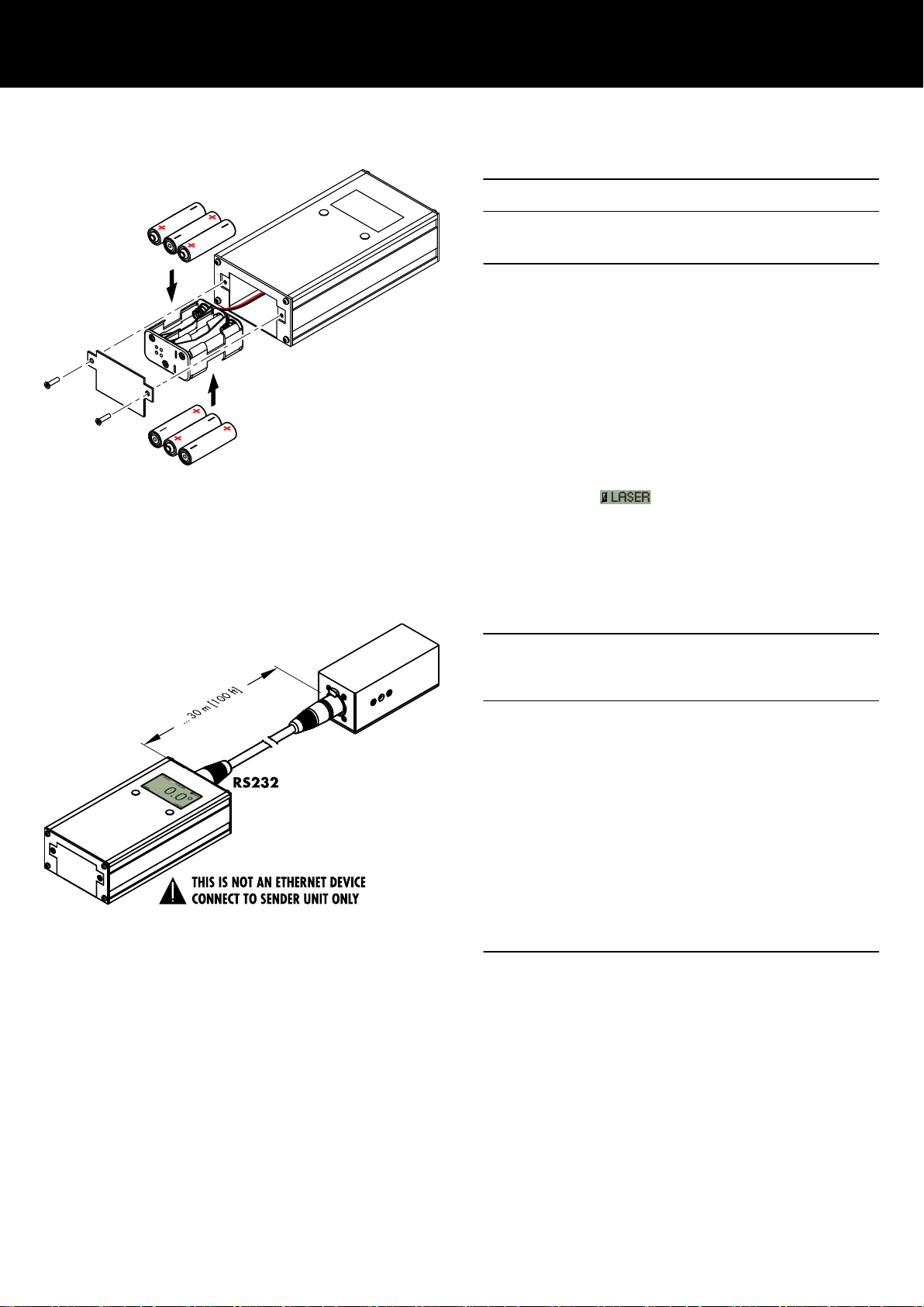
3.1 Installing the batteries
NOTICE!
To power the ArraySight inclinometer system, professional high
power Alkaline batteries (6 x AA - 1.5 VDC) must be used.
1. To insert and remove the batteries, undo the two M3 screws
on the end of the meter unit and slide out the battery holder.
↳
Observe the correct polarity.
2. Reinsert the battery holder and redo the screws.
To conserve battery life, the meter unit is set to power down after
one minute of inactivity by factory default. This can be adjusted in
the Þ «Auto power» menu.
Note: Once the battery voltage drops below 7.75 V
(approx. 24%) , the laser unit will be switched off and is no
more accessible. The battery icon on the display will be
crossed out Þ
.
However, the meter unit remains operating and angle
measurements are still possible.
3.2 Connecting the units
NOTICE!
Potential risk of malfunction and/or damaging to
components!
The meter unit is not an Ethernet device!
DO NOT connect the meter unit to any Ethernet port or device
such as Ethernet switches.
The meter unit is equipped with an RS232 interface and provides
the power supply and communication for the direct connection of a
single sender unit for read out.
Connect the sender unit to the meter unit using the enclosed,
shielded CAT5e 1:1 cable with etherCON connectors.
For this purpose, the meter and sender units are equipped with
corresponding etherCON connector sockets.
Cable lengths of up to 30 m (100 ft) are allowed.
DO NOT use any cables other than specified above.
d&b ArraySight Manual 1.7 en8
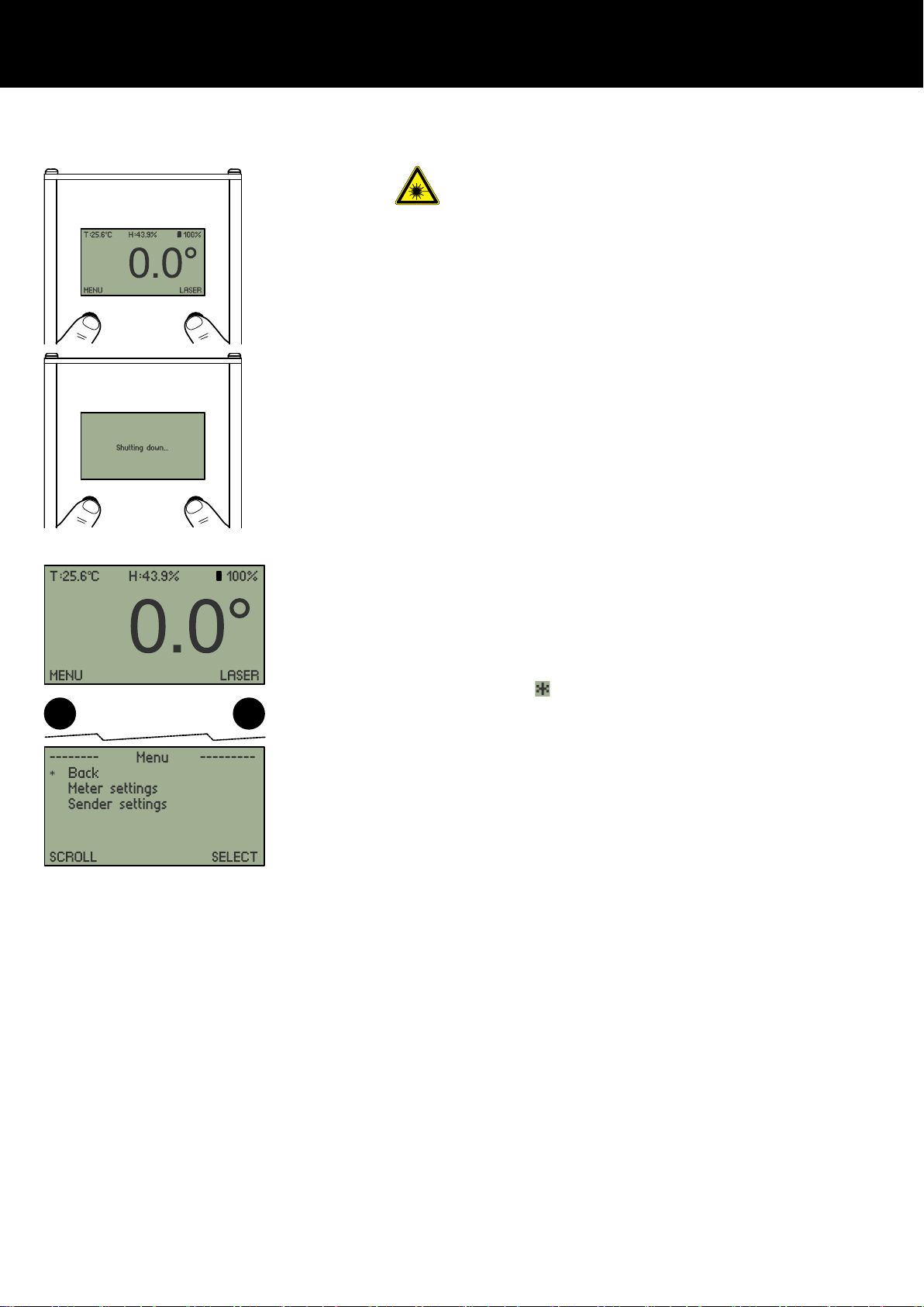
3.3 Switching on/switching off Please observe the "Safety precautions when using
laser equipment!"
1. To switch on the meter unit, hold down both buttons below the
screen.
↳
The menu screen will illuminate and initially display the d&b
logo. The unit will then switch to the «Home» screen and
display the current angle readout.
2. Release both buttons.
3. To power down the meter unit (and the connected sender
unit), proceed in the same manner until the «Shutting down»
message is displayed.
3.4 User interface of the meter unit
The meter unit features a detailed graphical display with an
intuitive on-screen menu system.
Navigation through the menus is by two buttons below the display.
Within the main menu and the submenus, the left-hand button is
generally used to scroll down through the menu items
Þ «SCROLL». The corresponding menu items are marked by an
asterisk (
).
The right-hand button is used to select a function Þ «SELECT».
Apart from that, the buttons have different functions within the
various submenus. The current function is always indicated above
each button (e.g. «BACK», SET, «CANCEL», «INC»...)
The display is backlit for viewing in all light conditions.
d&b ArraySight Manual 1.7 en 9
 Loading...