

DB Audio DS10 User Manual
D
DS10
Manual 1.5 en

d
u
c
t
General information
DS10 Manual
Version: 1.5 en, 01/2016, D2027.EN .01
Copyright © 2016 by d&b audiotechnik GmbH; all rights
reserved.
Keep this manual with the product or in a safe place
so that it is available for future reference.
We recommend you to regularly check the d&b website for the
latest version of this manual.
When reselling this product, hand over this manual to the new
owner.
If you supply d&b products, please draw the attention of your
customers to this manual. Enclose the relevant manuals with the
systems. If you require additional manuals for this purpose, you
can order them from d&b.
d&b audiotechnik GmbH
Eugen-Adolff-Strasse 134, D-71522 Backnang, Germany
T +49-7191-9669-0, F +49-7191-95 00 00
docadmin@dbaudio.com, www.dbaudio.com

Explanation of graphical symbols
The lightning symbol within a triangle is intended to alert
the user to the presence of uninsulated "dangerous
voltages" within the unit’s chassis that may be of
sufficient magnitude to constitute a risk of electric shock
to humans.
The exclamation point within a triangle is intended to
alert the user to the presence of important operating and
service instructions in the literature accompanying the
product.
Before using this product, carefully read the
applicable items of the following safety instructions.
1. Keep these instructions for future reference.
2. Read these instructions.
3. Heed all warnings.
4. Follow all instructions.
5. Keep water or other liquids away from the unit. Do not place
liquid filled containers, for example beverages, on top of the
unit.
6. Do not operate the unit while it is wet or standing in liquid.
7. Always operate the unit with the chassis ground wire
connected to the electrical safety earth. Do not defeat the
safety purpose of a grounding-type plug. A grounding-type
plug has two blades and a third grounding prong. The third
prong is provided for your safety. If the provided plug does
not fit into your outlet, consult an electrician for replacement of
the obsolete outlet.
8. Do not use this unit if the power cord is damaged or frayed.
Protect the power cord from being walked upon or pinched,
particularly at the plugs and the point where it exits from the
apparatus.
9. The unit is intended for use in a 19" rack. Follow the mounting
instructions. When a rack on wheels is used, exercise caution
when moving the loaded rack to avoid injury from tipping
over.
10. Unplug this apparatus during lightning storms or when unused
for long periods of time.
11. Lay all cables connected to the unit carefully so that they
cannot be crushed by vehicles or other equipment and that no
one can either step on them or trip over them.
12. Refer all servicing to qualified service personnel. Servicing is
required when the apparatus has been damaged in any way
such as:
– Power-supply cord or plug is damaged.
– Liquid has been spilled into the unit.
– An object has fallen into the unit.
– The unit has been exposed to rain or moisture.
– The unit does not operate normally.
– The unit was dropped or the chassis is damaged.
– Do not remove top or bottom covers. Removal of the covers
will expose hazardous voltages. There are no user
serviceable parts inside and removal may void the warranty.
13. Use the mains plug as the disconnecting device and keep it
readily accessible. If the mains plug is not readily accessible
due to mounting in a 19" rack, then the mains plug for the
entire rack must be readily accessible.
14. An experienced user must always supervise the equipment,
especially if inexperienced adults or minors are using the
equipment.
IMPORTANT SAFETY INSTRUCTIONS
d&b DS10 Manual 1.5 en 3

1. DS10 Audio network bridge....................................... 5
1.1. Intended use............................................................................ 5
1.2. Scope of supply...................................................................... 5
2. Technical specifications.................................................. 7
3. Startup.................................................................................. 8
3.1. Overview................................................................................. 8
3.2. Rack mounting......................................................................... 9
3.3. Mains connection.................................................................... 9
3.4. Front panel............................................................................ 10
3.4.1. BYPASS/NETWORK......................................................... 10
3.4.2. DIGITAL OUT 1 – 4.......................................................... 10
3.4.3. DIGITAL IN 1 – 4............................................................. 10
3.4.4. ETH1 - ETH4...................................................................... 11
3.4.5. SYNC ERROR/SUBSCRIBED........................................... 12
3.5. Rear panel............................................................................. 13
3.5.1. ETH 5/MODE ETH 3........................................................ 13
3.5.2. DIGITAL OUT 5 – 16....................................................... 13
3.6. Meta data............................................................................. 13
4. Rack connections........................................................... 14
4.1.
Use with d&b Touring rack I/O panel................................ 14
5. Application examples.................................................. 15
5.1.
Redundant............................................................................. 16
5.2. FoH........................................................................................ 17
5.3. Wireless control with external switches............................... 18
5.4. Wireless control without external switches.......................... 19
6. DS10 Firmware update............................................... 20
7. Manufacturer's Declarations.................................... 21
7.1.
EU declaration of conformity (CE symbol).......................... 21
7.2. WEEE Declaration (Disposal).............................................. 21
7.3. Licenses and patents............................................................. 21
Contents
d&b DS10 Manual 1.5 en4
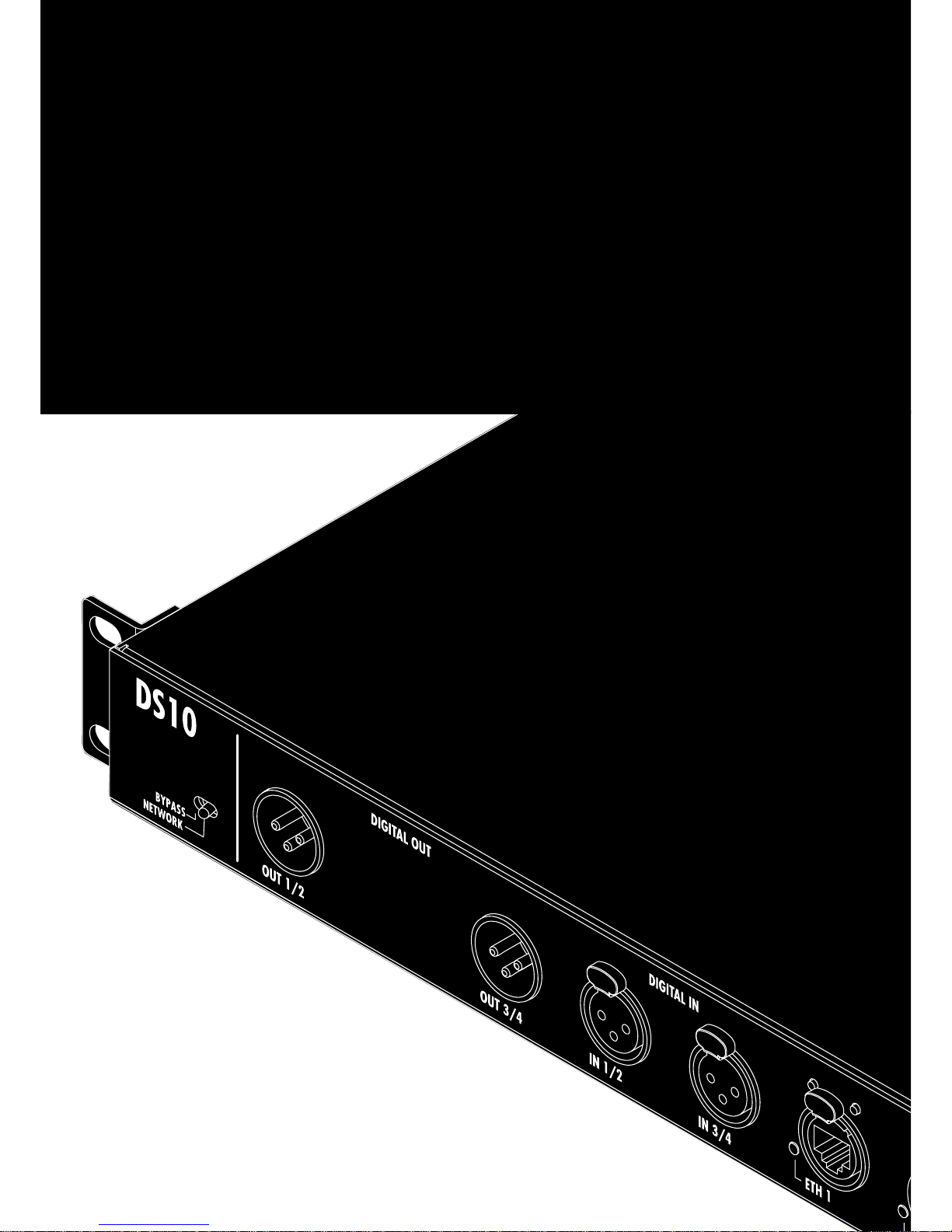
1.1. Intended use
The d&b DS10 is a 16 output channel break-out box connecting
the Dante audio network to the AES3 digital audio standard.
In addition, 4 x AES3 input channels are provided for use as a
simple break-in box, e.g. at Front of House.
Configuration and control of the device is performed using the
Dante Controller software, which enables networkwide routing
from one single software platform. The software is available for
free download at
www.audinate.com.
The DS10 is mainly intended for use within the d&b Touring rack
assemblies.
NOTICE!
The device complies with the electromagnetic compatibility
requirements of EN 55103 (product family standard for audio,
video, audio-visual and entertainment lighting control apparatus for
professional use) for the environments E1 (residential), E2 (business
and commercial), E3 (outdoor use in urban areas) and E4
(outdoor use in rural areas).
Acoustic interference and malfunctions may occur if the unit is
operated in the immediate vicinity of high-frequency transmitters
(e.g. wireless microphones, mobile phones, etc.). Damage to the
device is unlikely, but cannot be excluded.
1.2. Scope of supply
Before starting up the device, please verify the shipment for
completeness and proper condition of the items.
If there is any sign of obvious damage to the unit and/or the
power cord, do not operate the unit and contact your local dealer
from whom you received it.
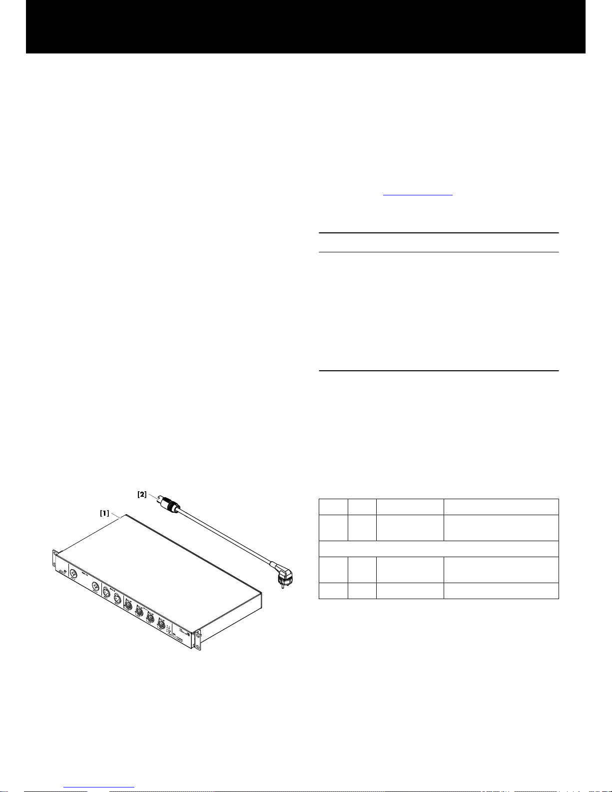
Z4010 DS10
Pos. Qty. d&b Code Description
[1] 1 Z4010 d&b DS10
Audio network bridge.
Including:
[2] 1 Z2610.xxx Power cord
(specific to country).
1 D2027.EN .01 DS10 Manual.
1. DS10 Audio network bridge
d&b DS10 Manual 1.5 en 5
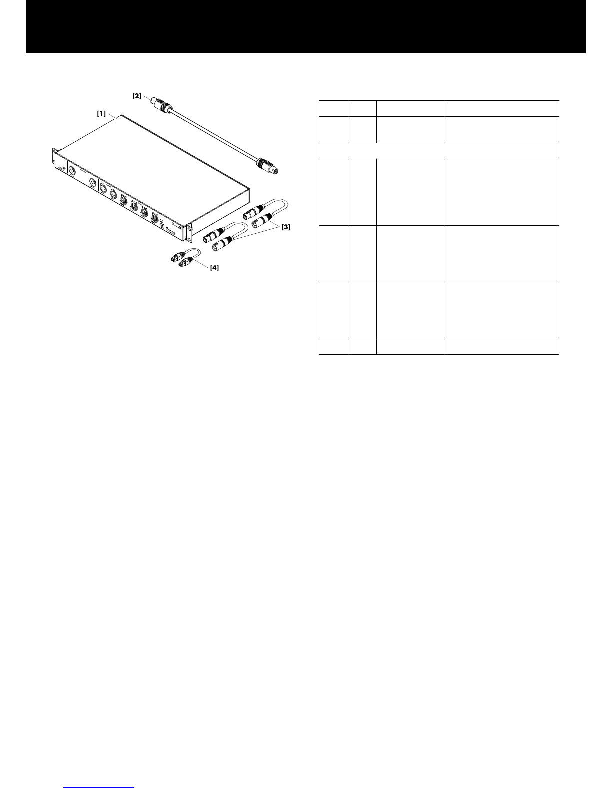
Z5563 DS10 Rack upgrade kit
Pos. Qty. d&b Code Description
[1] 1 Z4010 d&b DS10 Audio network
bridge.
Including:
[2] 1 Z2610.130 Power cord (powerCON/
powerCON.
Used to connect the device to
auxiliary powerCON socket
at the rear of the mains
distributor.
[3]
2 E7500.024 AES/EBU XLR cable.
Used to connect the digital
outputs 1/2 and 3/4 to the
digital inputs D1/2 and D3/4
of the I/O panel.
[4]
1 K6018.025 CAT5e patch cable.
Used to connect the ETH 3
connector of the device to the
ETH 1 connector of the I/O
panel.
1
D2027.EN .01 DS10 Manual.
Note: For rack assembly instructions please refer to
Þ Chapter 4. "Rack connections" on page 14.
d&b DS10 Manual 1.5 en6
Power supply
Mains connector
powerCON
®
Rated mains voltage 100 to 240 V, 50 – 60 Hz
Overvoltage protection Up to 400 V AC
Power consumption 10 W (max)
Digital inputs
Connectors 3 pin XLR female, AES3
Pin assignment 1 = GND, 2 = AES Signal, 3 = AES Signal
Input impedance 110 ohms
Sampling 32 – 192 kHz
Synchronization Sample Rate Converter (SRC)
Digital outputs
Connectors
3 pin XLR male, AES3
Pin assignment 1 = GND, 2 = AES Signal, 3 = AES Signal
Output impedance 110 ohms
Sampling 48/ 96 kHz
Synchronization Dante network
Network
Connectors
etherCON
®
built-in 5-port Ethernet switch
100/1000 Mbit
Controls and indicators
BYPASS/NETWORK
Toggle switch
Switch port modes/Audio loss RGB LEDs
SYNC ERROR LED indicator red
SUBSCRIBED (RX Subscription) LED indicator green
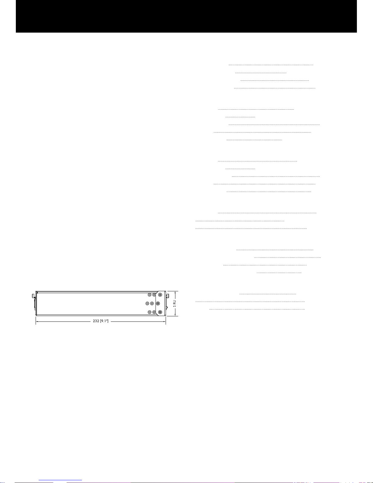
Dimensions and weight
Height x width x depth
1 RU x 19" x 232 mm
1 RU x 19" x 9.1"
Weight 3.75 kg / 8.26 lb
2. Technical specifications
d&b DS10 Manual 1.5 en 7
 Loading...