

Page 1
Z5440
Z
Mounting instructions 1.2 en
Page 2

General information
Z5440 Mounting instructions
Version: 1.2 en, 11/2014, D2620.EN .01
Copyright © 2014 by d&b audiotechnik GmbH; all rights
reserved.
Keep these mountings instructions with the product or
in a safe place so that they are available for future
reference.
When reselling this product, hand over these mounting instructions
to the new customer.
d&b audiotechnik GmbH
Eugen-Adolff-Strasse 134, D-71522 Backnang, Germany
T +49-7191-9669-0, F +49-7191-95 00 00
docadmin@dbaudio.com, www.dbaudio.com
Page 3

Contents
1. Z5440 Wall mount bracket......................................... 4
1.1. Scope of supply........................................................... 4
1.2. Safety precautions....................................................... 4
1.3. Intended use................................................................ 5
2. Assembly............................................................................ 6
3. Built-in dimensions.......................................................... 8
4. Declarations...................................................................... 9
4.1. Manufacturer's declaration......................................... 9
4.2. Disposal....................................................................... 9
5. Fixing template............................................................. 10
d&b Z5440 Mounting instructions 1.2 en 3
Page 4
1. Z5440 Wall mount bracket
1.1. Scope of supply
Please verify the shipment for completeness and proper condition
of the items.
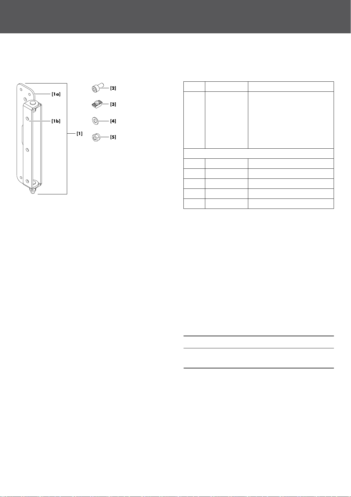
Qty. d&b Code Description
1 Z5440 Wall mount bracket [1] consisting
of:
– Wall plate [1a]
– Cabinet hinge plate [1b]
Note: Due to the size and easy
handling of the wall plate [1a], it
also serves as the fixing template.
Including:
3 Allen hex screw M6 x 12 [2]
3 T-slot nut 8 mm / M6 [3]
2 U washer 6.4 [4]
2 Self-securing nut M6 [5]
1 D2620.EN .01 Z5440 Mounting instructions
1.2. Safety precautions
General safety
Installation and setup should only be carried out by qualified and
authorized personnel observing the valid national Rules for the
Prevention of Accidents (RPA).
It is the responsibility of the person installing the assembly to ensure
that the suspension/fixing points are suitable for the intended use.
Always carry out a visual and functional inspection of the items
before use. In case there is any doubt as to the proper functioning
and safety of the items, these must be withdrawn from use
immediately.
Load safety information
NOTICE!
Only use appropriate mounting parts (anchors and screws) that
are suitable for the intended application.
The maximum permitted working load of the Z5440 Wall mount
bracket is 16 kg (35 lb), which corresponds to the weight of a
complete 24C/24C-E assembly.
d&b Z5440 Mounting instructions 1.2 en4
Page 5

Mounting recommendations
Basically, it does not matter in what position you attach the wall
mount bracket to the cabinet.
However, when you mount the bracket to a complete 24C/24C-E
assembly, we recommend you to attach it to the 24C cabinet
instead of the extender.
It is advisable to attach the bracket to the upper part of the 24C
cabinet close to the connector panel, as shown in the graphic
opposite.
1.3. Intended use
The d&b Z5440 Wall mount bracket must only be used in
conjunction with applicable d&b column loudspeakers.
It is intended for direct and parallel wall mounting with a maximum
distance of 26 mm (1") between the column loudspeaker and the
wall.
The wall plate can be attached in two ways to allow horizontal
aiming of the column in both directions, to the right or to the left.
d&b Z5440 Mounting instructions 1.2 en 5
Page 6

2. Assembly
Tools required
– Wrench/spanner size #10 mm
– Torque wrench with Allen key insert size #5 mm
T-slot nut principle
The T-slot nut is a specially shaped nut which allows easy fitting.
It is simply inserted into the T-slot profile and turned through 90°
for final positioning.
Preparing the hinge plate [1b]
1. Insert all Allen hex screws [2] into the hinge plate [1b].
2. Fit the T-slot nuts [3] to the screws and turn the nuts 3-4 times.
Attaching the hinge plate to the cabinet
1. At rear of the cabinet, insert the T-slot nuts into the T-slot profile
of the cabinet.
2. Turn the first screw through 90° to fix the T-slot nut in place.
3. Tighten the screw to a torque of 8 N×m.
4. To fix the remaining nuts, proceed in the same manner.
d&b Z5440 Mounting instructions 1.2 en6
Page 7

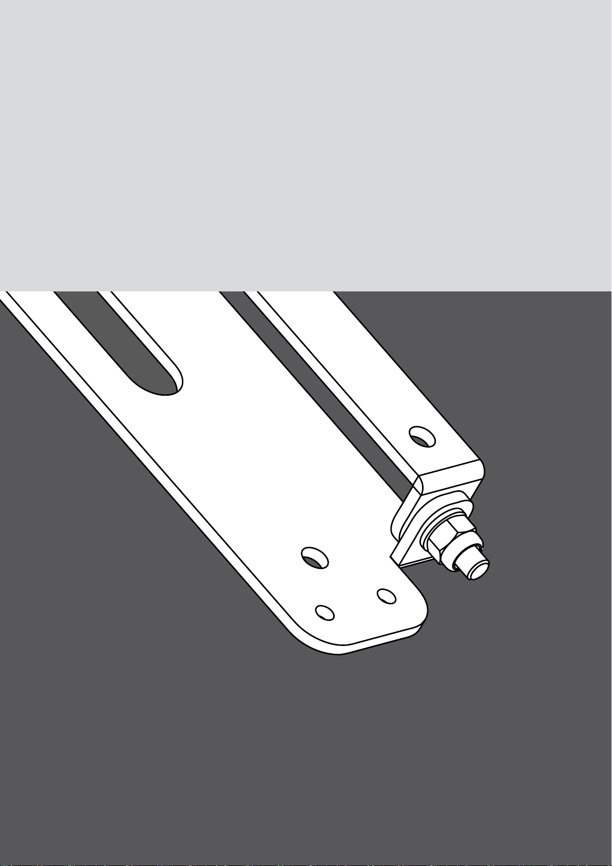
Attaching the cabinet to the wall plate [1a]
Provided you have mounted the wall plate in the desired position
on the wall, proceed as follows:
1. Attach the cabinet to the wall plate, as shown in the graphic
opposite.
2. Attach the U washers [4] and the self-securing nuts [5].
3. Slightly tighten the nuts.
4. Set your desired horizontal aiming.
5. Finally tighten all nuts to fix the cabinet in its horizontal
position.
d&b Z5440 Mounting instructions 1.2 en 7
Page 8

3. Built-in dimensions
Built-in dimensions in mm [inch]
From left: Total height of single 16C and 24C column, total height of 24C with 24C-E extender, minimum and maximum depth.
d&b Z5440 Mounting instructions 1.2 en8
Page 9

4. Declarations
4.1. Manufacturer's declaration
This declaration covers:
– d&b Z5440 , Wall mount bracket.
National standards and technical specifications
applied:
DIN 18 800, DIN 1055, BGV C1.
Backnang, 2014-02-04
Frank Bothe,
Head of R&D
d&b audiotechnik GmbH
4.2. Disposal
When out of use the rigging components must be disposed of in
accordance with the national environmental regulations.
Ensure that damaged rigging components are disposed of in a
way that they cannot be used again.
d&b Z5440 Mounting instructions 1.2 en 9
Page 10

5. Fixing template
Z5440 Fixing template, Scale 1:1.
Note: Observe your printer settings and scaling.
d&b Z5440 Mounting instructions 1.2 en10
Page 11

Page 12

D2620.EN .01, 11/2014 © d&b audiotechnik GmbH
www.dbaudio.com
 Loading...