

Page 1

Z5401 Wall mount S
Mounting instructions (1.2 EN)
Page 2

General information
Z5401 Wall mount S
Mounting instructions
Version: 1.2 EN, 03/2013, D2956.EN .01
Copyright © 2013 by d&b audiotechnik GmbH; all rights
reserved.
Keep this manual with the product or in a safe place
so that it is available for future reference.
When reselling this product, hand over this manual to the new
customer.
d&b audiotechnik GmbH
Eugen-Adolff-Strasse 134, D-71522 Backnang, Germany
T +49-7191-9669-0, F +49-7191-95 00 00
docadmin@dbaudio.com, www.dbaudio.com
Page 3

Contents
1. Z5401 Wall mount S...................................................... 4
1.1. Scope of supply........................................................... 4
1.2. Safety precautions....................................................... 4
1.3. Intended use................................................................ 4
1.4. Mounting options and angle settings......................... 5
1.5. Assembly...................................................................... 5
2. Fixing template................................................................ 7
3. Built-in dimensions.......................................................... 8
4. Declarations.................................................................... 10
4.1. Manufacturer's declaration...................................... 10
4.2. Disposal..................................................................... 10
d&b Z5401 Wall mount S, Mounting instructions (1.2 EN) 3
Page 4
1. Z5401 Wall mount S
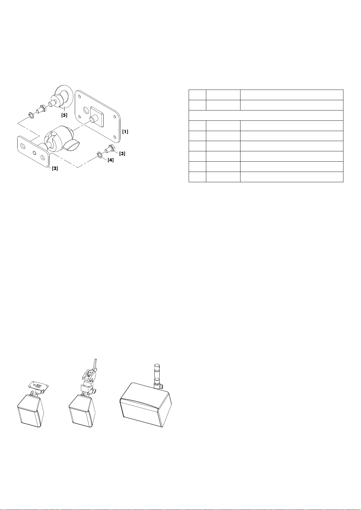
Fig. 1: Scope of supply
1.1. Scope of supply
Please verify the shipment for completeness and proper condition
of the items.
Qty. d&b Code Description
1 Z5401 d&b Wall mount S
Including:
1 Mounting plate M10 [1]
1 Ball joint adapter [2]
2 Hex head bolt M8 x 18 [3]
2 Spring washer [4]
1 Q9031 M8 Safety eyebolt [5]
1 D2956 Mounting instructions
1.2. Safety precautions
General safety
Installation and setup should only be carried out by qualified and
authorized personnel observing the valid national Rules for the
Prevention of Accidents (RPA).
It is the responsibility of the person installing the assembly to ensure
that the suspension/fixing points are suitable for the intended use.
Always carry out a visual and functional inspection of the items
before use. In case you have any doubt as to the proper
functioning and safety of the items, these must be withdrawn from
use immediately.
Load safety information
The maximum permitted working load of the Z5401 Wall mount S
is 3 kg (6.6 lb) (according to BGV C1) which implies the weight of
one 4S or 5S cabinet.
1.3. Intended use
The d&b Z5401 Wall mount S must only be used in conjunction
with the d&b xS-Series loudspeakers 4S and 5S as described in
these mounting instructions.
The wall mount can be mounted directly to walls, ceilings or other
suitable surfaces.
d&b Z5401 Wall mount S, Mounting instructions (1.2 EN)4
Page 5

The M10 socket of the ball joint adapter allows the loudspeakers
to be connected to different d&b mounting accessories such as:
– E6532 Super Clamp with
E6533 M10 adapter for Super Clamp
– Z5029 TV spigot
– Z5035 M10 to 3/8" adapter
– Z5034 Stand adapter
Note: Refer to the specific mounting instructions for assembly
and operation of these accessories.
1.4. Mounting options and angle settings
The following mounting options and angle settings are applicable
no matter whether the cabinets are mounted to walls or ceilings or
other suitable surfaces.
4S loudspeaker
Depending on the location of the threaded inserts on the cabinet
(bottom or top), angles can be set in the range from 0° to –90°
(bottom setup) or from 0° to –40° (top setup).
NOTICE!
For unprotected outdoor operation the Z5401 cabinet must be
installed with the M8 inserts located at the top of the cabinet's rear
panel (top setup).
5S loudspeaker
If the 5S cabinet is mounted to a wall, both horizontal or vertical
mounting is possible. Angles can be set from 0° to –38° (vertical
set up) or 0° to –70° (horizontal setup).
If the cabinet is mounted to a ceiling, the horizontal setup is
recommended.
1.5. Assembly
Tools required:
– Open-ended spanner/wrench (size #13 and #17)
– Allen hex key 3 mm
Mounting plate M10
NOTICE!
Only use mounting parts (fixing anchors and screws) that are
suitable for the intended application.
To mount the 4S and 5S cabinets to walls, ceilings or other
surfaces, use the Mounting plate M10.
A corresponding fixing template is supplied with these mounting
instructions. Refer to Þ Chapter 2. "Fixing template"
on page 7.
d&b Z5401 Wall mount S, Mounting instructions (1.2 EN) 5
Page 6

An additional 12 mm (0.47") hole is provided on the mounting
plate as a feed-through for the connection cable.
Ball joint adapter
The ball joint adapter of the wall mount is equipped with a set
screw. It is used to preset the clamping of the ball joint.
If necessary, adjust the set screw using the 3 mm Allen hex key.
Attaching the ball joint to the cabinet
NOTICE!
– Only use the supplied and specified screws [3], otherwise
there a risk of damaging the threaded inserts.
– Always use the spring washers [4] to prevent the bolts from
slackening.
1. Attach the wall mount to the two M8 threaded inserts on the
rear panel of the cabinet.
2. Insert the screws together with the U and spring washers and
tighten them using the spanner (#13).
Alternatively, one screw may be replaced by the supplied
eyebolt [5] to allow the attachment of a secondary safety
wire.
Attaching the assembly to the mounting plate
To attach the assembly to the mounting plate, proceed as follows:
1. Slacken the fixing screw [F] and the set screw [S] to release
the M10 socket [I] of the ball joint.
2. Attach the assembly and bolt down the threaded insert to the
mounting plate.
3. Tighten the M10 socket using the spanner (#17).
4. Set the desired angle of the cabinet and adjust the set screw
[S].
5. Finally tighten the fixing screw [F].
d&b Z5401 Wall mount S, Mounting instructions (1.2 EN)6
Page 7

2. Fixing template
Fig. 2: Z5401 Wall mount S, fixing template, shown with center ( ) of the 4S/5S cabinets.
Note: Mind your printer settings and scaling.
d&b Z5401 Wall mount S, Mounting instructions (1.2 EN) 7
Page 8

3. Built-in dimensions
Fig. 3: Z5401 Wall mount S, 4S wall mounted, top setup, built-in dimensions in mm [inch]
Fig. 4: Z5401 Wall mount S, 4S wall mounted, bottom setup, built-in dimensions in mm [inch]
Fig. 5: Z5401 Wall mount S, 4S ceiling mounted, built-in dimensions in mm [inch]
d&b Z5401 Wall mount S, Mounting instructions (1.2 EN)8
Page 9

Fig. 6: Z5401 Wall mount S, 5S wall mounted, vertical setup, built-in dimensions in mm [inch]
Fig. 7: Z5401 Wall mount S, 5S wall mounted, horizontal setup, built-in dimensions in mm [inch]
d&b Z5401 Wall mount S, Mounting instructions (1.2 EN) 9
Page 10

4. Declarations
4.1. Manufacturer's declaration
This declaration covers:
– d&b Z5401, Wall mount S.
National standards and technical specifications
applied:
DIN 18 800, DIN 1055, BGV C1, BGI 810-3.
Backnang, 2011-03-25
Frank Bothe,
Head of R&D
d&b audiotechnik GmbH
4.2. Disposal
When out of use the rigging components must be disposed of in
accordance with the national environmental regulations.
Ensure that damaged rigging components are disposed of in a
way that they cannot be used again.
d&b Z5401 Wall mount S, Mounting instructions (1.2 EN)10
Page 11

D2956.EN .01, 03/2013 © d&b audiotechnik GmbH
www.dbaudio.com
 Loading...