

Page 1
Z5398
Z
Mounting instructions 1.1 en
Page 2

General information
Z5398 Mounting instructions
Version: 1.1 en, 07/2014, D2818.EN .01
Copyright © 2014 by d&b audiotechnik GmbH; all rights
reserved.
Keep these mountings instructions with the product or
in a safe place so that they are available for future
reference.
When reselling this product, hand over these mounting instructions
to the new customer.
d&b audiotechnik GmbH
Eugen-Adolff-Strasse 134, D-71522 Backnang, Germany
T +49-7191-9669-0, F +49-7191-95 00 00
docadmin@dbaudio.com, www.dbaudio.com
Page 3

Contents
1. Z5398 YP Horizontal bracket..................................... 4
1.1. Scope of supply and weight................................................... 4
1.2. Safety precautions................................................................... 4
1.3. Intended use............................................................................ 4
1.4. Mounting options and angle settings..................................... 5
1.5. Assembly.................................................................................. 6
2. Fixing template................................................................. 7
3. Built-in dimensions........................................................... 8
4. Declarations..................................................................... 10
4.1.
Manufacturer's declaration.................................................. 10
4.2. Disposal................................................................................. 10
d&b Z5398 Mounting instructions 1.1 en 3
Page 4
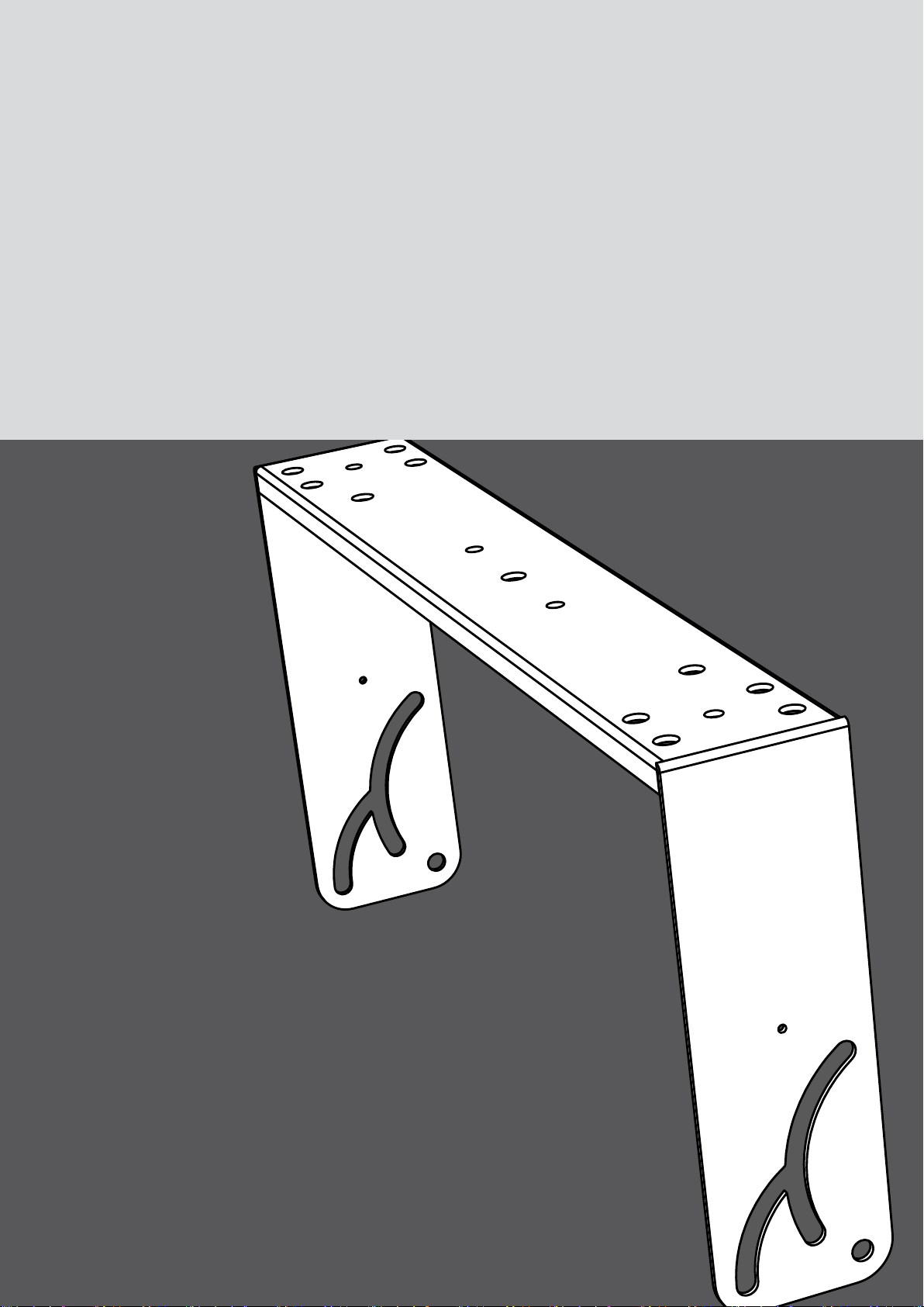
1. Z5398 YP Horizontal bracket
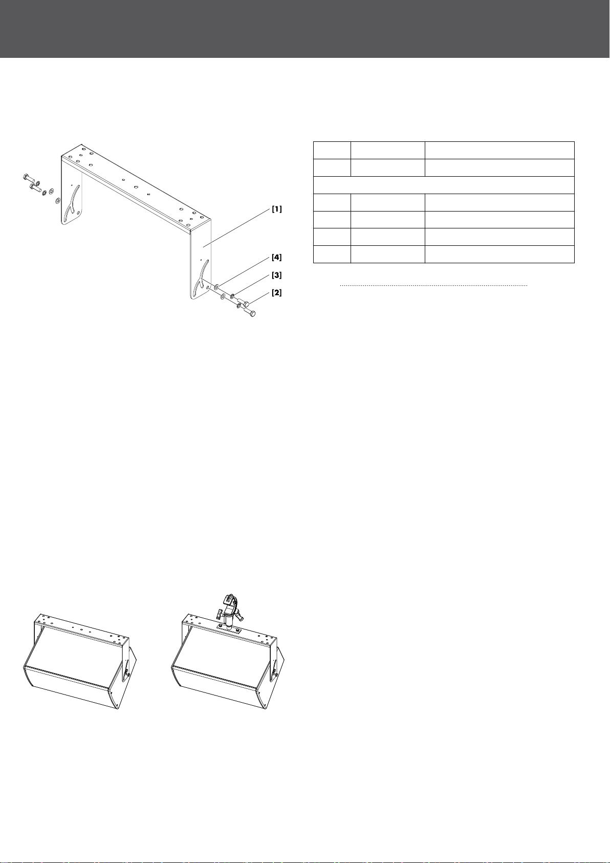
1.1. Scope of supply and weight
Please verify the shipment for completeness and proper condition
of the items.
Qty. d&b Code Description
1 Z5398 YP Horizontal bracket [1]
Including:
4 Hex head bolt M10 x 25 [2]
4 Spring washer [3]
4 U washer [4]
1 D2818.EN .01 Z5398 Mounting instructions
Weight 2 kg (4.4 lb)
Scope of supply
1.2. Safety precautions
General safety
Installation and setup should only be carried out by qualified and
authorized personnel observing the valid national Rules for the
Prevention of Accidents (RPA).
It is the responsibility of the person installing the assembly to ensure
that the suspension/fixing points are suitable for the intended use.
Always carry out a visual and functional inspection of the items
before use. In case you have any doubt as to the proper
functioning and safety of the items, these must be withdrawn from
use immediately.
Load safety information
The Z5398 YP Horizontal bracket is designed to support one YP
loudspeaker (Yi7P or Yi10P).
No additional loads must be added.
1.3. Intended use
The d&b Z5398 YP Horizontal bracket must only be used in
conjunction with d&b YP or YiP cabinets (Y7P/Yi7P or Y10P/
Yi10P) as described in these mounting instructions.
The bracket can be:
– directly mounted to walls.
– directly mounted to ceilings or other suitable surfaces.
– horizontally flown from overhead bars or trusses with a tube
diameter bewtween 40 mm to 70 mm (1.5" to 2.75") using
the Z5010 TV spigot with fixing plate in conjunction with the
Z5012 Pipe clamp.
Note: Refer to the specific mounting instructions for assembly
and operation of these accessories.
d&b Z5398 Mounting instructions 1.1 en4
Page 5

Z5398 Mounting holes
1.4. Mounting options and angle settings
Mounting holes are provided on the tie bar of the bracket.
One centered 9 mm (0.35") hole is provided at each end of the tie
bar for fixing the bracket directly to walls or ceilings or other
suitable surfaces.
Two centered 9 mm (0.35") holes at the d&b standard spacing of
115 mm (4.5") are provided to allow the attachment of the Z5010
TV spigot.
Five mounting holes are provided at each end of the tie bar to
attach the Z5044 MAX Bracket connector, the Z5053 Ci60/Ci90
Bracket connector or the Z5054 Ci60/Ci90 Flying adapter.
One 11 mm (0.43“) hole [a] and two semi-circular slots [b], [c]
are located at each end of the bracket.
Using the M10 threaded inserts at the top and bottom of the
loudspeaker cabinet, the bracket can be attached in two directions
to allow angle settings over a range of 105°, starting from +15°
through to –90°. The following mounting options and angles
settings are possible.
Option 1
The bracket is attached to the cabinet with hole [a] facing to the
front of the cabinet. Both bolts are fitted into slot [b].
The vertical coverage angle can be set over a range of 30°,
starting from 0° to –30°.
Option 2
The bracket is attached to the cabinet with hole [a] facing to the
back of the cabinet. One bolt is fitted into hole [a] and the second
one is fitted into the axis of slot [b] and slot [c] to allow the bolt to
move in slot [c].
The vertical coverage angle can be set over a range of 60°,
starting from –30° to –90°.
Option 3
The bracket is attached to the cabinet with hole [a] facing to the
back of the cabinet. Both bolts are fitted into slot [b].
The vertical coverage angle can be set over a range of 15°,
starting from 0° to +15°.
d&b Z5398 Mounting instructions 1.1 en 5
Page 6

1.5. Assembly
Attaching the bracket to walls or ceilings
NOTICE!
Only use mounting parts (fixing anchors and screws) that are
suitable for the intended application.
Observe the occurring extraction forces acting on the fixing
anchors and screws. The rated extraction forces for the respective
application (wall or ceiling mounting) and cabinet are listed in the
following table.
Application Rated extraction forces
Wall mounting 300 N
Ceiling mounting 200 N
To attach the bracket to walls or ceilings, use the holes shown in
the graphic opposite to provide adequate support.
A corresponding fixing template is supplied with these mounting
instructions. Refer to Þ Chapter 2. "Fixing template"
on page 7.
Attaching the cabinet to the bracket
NOTICE!
Only use the supplied and specified screws [2], otherwise there a
risk of damaging the threaded inserts.
Always use the spring washers [3] and U washers [4] to prevent
the bolts from slackening.
Tools required:
– Open-ended spanner/wrench (size #17)
1. Attach the cabinet to the prepared bracket.
2. Insert the screws together with the spring and U washers.
3. Align the cabinet and tighten the screws.
d&b Z5398 Mounting instructions 1.1 en6
Page 7

2. Fixing template
Z5398 Fixing template
d&b Z5398 Mounting instructions 1.1 en 7
Page 8

3. Built-in dimensions
Z5398 Dimensions in mm [inch]
Z5398 Mounting options 1,2 and 3 with built-in dimensions in mm [inch]
d&b Z5398 Mounting instructions 1.1 en8
Page 9

Built-in dimensions Z5010/Z5012 Assembly
d&b Z5398 Mounting instructions 1.1 en 9
Page 10

4. Declarations
4.1. Manufacturer's declaration
This declaration covers:
– d&b Z5398, YP Horizontal bracket.
National standards and technical specifications
applied:
DIN 18 800, DIN 1055, DGUV Vorschrift 17.
Backnang, 2014-06-23
Frank Bothe,
Head of R&D
d&b audiotechnik GmbH
4.2. Disposal
When out of use the rigging components must be disposed of in
accordance with the national environmental regulations.
Ensure that damaged rigging components are disposed of in a
way that they cannot be used again.
d&b Z5398 Mounting instructions 1.1 en10
Page 11

Page 12

D2818.EN .01, 07/2014 © d&b audiotechnik GmbH
www.dbaudio.com
 Loading...