

Page 1
Z5396
Y
Rigging manual 1.1 en
Page 2

General information
Z5396 Rigging manual
Version: 1.1 en, 08/2014, D2720.EN .01
Copyright © 2014 by d&b audiotechnik GmbH; all rights
reserved.
Keep this manual with the product or in a safe place
so that it is available for future reference.
When reselling this product, hand over this manual to the new
customer.
If you supply d&b products, please draw the attention of your
customers to this manual. Enclose the relevant manuals with the
systems. If you require additional manuals for this purpose, you
can order them from d&b.
d&b audiotechnik GmbH
Eugen-Adolff-Strasse 134, D-71522 Backnang, Germany
T +49-7191-9669-0, F +49-7191-95 00 00
docadmin@dbaudio.com, www.dbaudio.com
Page 3

Contents
1. Z5396 Y Base plate........................................................ 4
1.1. Safety........................................................................... 4
1.1.1. Intended use............................................................. 4
1.1.2. General safety......................................................... 4
1.2. Scope of supply........................................................... 4
2. Assembly............................................................................ 5
2.1. Preparing the setup..................................................... 5
2.2. Order of assembly...................................................... 5
2.2.1. Y8/Y12 Ground stack............................................. 5
2.2.2. Mixed ground stack................................................. 7
3. Care and maintenance.................................................. 8
3.1.
Transport / Storing...................................................... 8
3.2. Visual and functional inspection................................. 8
4. Declarations...................................................................... 9
4.1.
Manufacturer's declaration......................................... 9
4.2. Disposal....................................................................... 9
d&b Z5396 Rigging manual 1.1 en 3
Page 4

1. Z5396 Y Base plate
1.1. Safety
1.1.1. Intended use
The Z5396 must only be used for ground stacked applications in
connection with d&b Y-Series Y8 and Y12 loudspeakers as
described in this manual.
The Base plate is not intended for flown use.
Limitations
The Base plate is designed to support a maximum of 3 x Y-TOP
cabinets when used directly on the ground.
A maximum of 6 x Y-TOP cabinets are allowed when using the
Base plate on top of an applicable d&b subwoofer, such as the
Y-SUB.
1.1.2. General safety
Installation and setup should only be carried out by qualified and
authorized personnel observing the valid national Rules for the
Prevention of Accidents (RPA).
Always carry out a visual and functional inspection of the items
before use. In case there is any doubt as to the proper functioning
and safety of the items, these must be withdrawn from use
immediately.
Please also refer to Þ Chapter 3. "Care and maintenance"
on page 8.
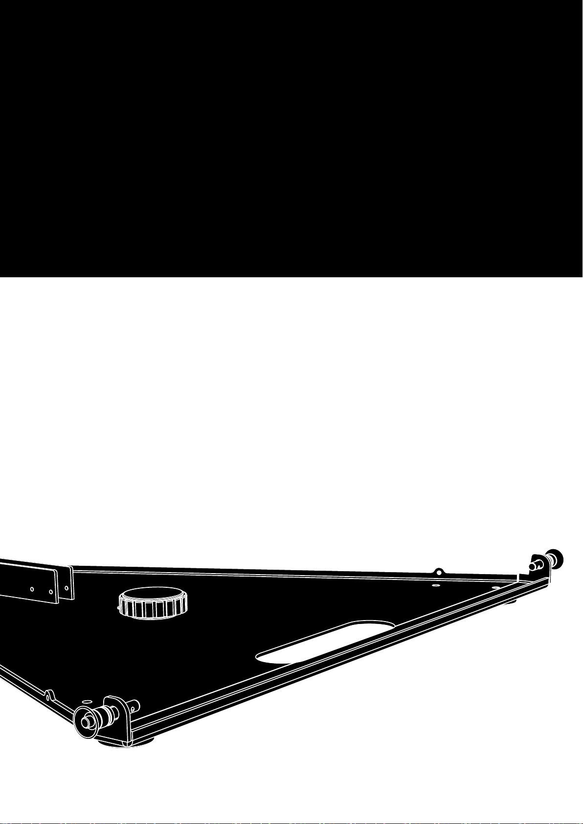
1.2. Scope of supply
Please verify the shipment for completeness and proper condition
of the items.
Qty.
d&b Code Description
1 Z5396 d&b Y Base plate [1]
Including:
1 Hand bolt M20 x 25 [2]
2 Locking pins 7 x 18 mm [3]
1 Locking pin 8 x 40 mm [4]
All items are undetachably attached to the plate using steel wire
ropes.
1 D2720.EN .01 Z5396 Rigging manual
d&b Z5396 Rigging manual 1.1 en4
Page 5

2. Assembly
WARNING!
Potential risk of personal injury and/or
damage to material!
Always secure ground stacked setups against movement and
possible tipping over.
Observe the maximum number of cabinets permitted. This is
particularly important when setting up mixed ground stacks.
2.1. Preparing the setup
General
Check the acoustical and mechanical setup using ArrayCalc and
prepare enough printouts for each array.
When on site first:
– Clear the working areas and ensure there is enough space to
set up the ground stack.
– Prepare the cables and link cables according to the number of
amplifier channels and cabinets used.
Inspections before setup
Before setup carry out a visual inspection of all system components
for faults. This also includes the loudspeakers and in particular the
rigging parts of the cabinets (Front and Splay/Rear links).
Damaged components must be withdrawn from use immediately.
Please follow the instructions given in Þ Chapter 3. "Care and
maintenance" on page 8.
2.2. Order of assembly
2.2.1. Y8/Y12 Ground stack
1. Attach the first cabinet to the Base plate
1. Place the Base plate on the ground.
2. Place the first cabinet onto the Base plate until the cabinet's
slots fit into the corresponding fixtures on the Base plate.
3. Insert and lock the Locking pins of the Base plate on both
sides.
d&b Z5396 Rigging manual 1.1 en 5
Page 6

Aiming of the first cabinet
Shown: –3.5°
2. Set vertical aiming of the first cabinet
The aiming of the first cabinet can be set to –7°, –3.5°, 0° or
+3.5°.
1. At the rear release both Locking pins of the cabinet's Splay link
from park position.
2. Fold out and insert the Splay link into the track of the Base
plate and align the hole of the link with the desired hole of the
Base plate.
3. Fix the angle of the cabinet using one Locking pin from the
Base plate.
3. Add further cabinets
Þ
At the front of the first cabinet release the Locking pins of the
Front links.
The Front links will slide out automatically.
Þ
4. Preset the splay angle
The splay angles between adjacent cabinets are defined using the
central rear rigging strands of the cabinets and can be set in the
range from 0° to 14° in 1° steps.
Þ
On the first cabinet, preselect the splay angle according to
your ArrayCalc simulation and insert and lock one Locking pin
in the appropriate hole.
5. Attach the next cabinet
1. Attach the next cabinet to the Front links.
2. Insert and lock the Locking pins on both sides.
d&b Z5396 Rigging manual 1.1 en6
Page 7

3. At the rear release both Locking pins of the upper cabinet's
Splay link.
4. Fold the Splay link of the upper cabinet into the rigging strand
of the bottom cabinet.
5. Raise the upper cabinet until the hook of the Splay link hooks
into the preset Locking pin.
6. Hold the cabinet in place and insert the second Locking pin
(Safety pin) from the bottom cabinet to fix the Splay link in
place.
To add further cabinets, proceed in the same manner until the
assembly is completed.
6. Rig the cabling
Connect the cables and link cables according to the number of
amplifier channels and cabinets used.
7. Check the assembly
Recheck the actual status of the entire assembly.
– Check all Front links on both sides of the cabinets and ensure
all Locking pins are properly inserted and locked.
– Check the splay angle settings and the Splay links on the rear
of the cabinets and ensure all Locking pins are properly
inserted and locked.
2.2.2. Mixed ground stack
For this purpose, the Base plate is equipped with an M20 hand
bolt [2] which can be attached to the M20 threaded insert of the
respective subwoofer.
Þ
Simply fit the Base plate onto the M20 threaded insert of the
subwoofer and tighten the hand bolt.
The assembly of the Y8/Y12 cabinets on top of the subwoofer is
carried out in the same manner as described in the previous
chapter.
Horizontal alignment
In addition, the Y8/Y12 assembly on top of the Subwoofer can be
horizontally aligned to the left or to the right. However, due to the
rubber feet of the Base plate, the angle is limited to 15° since the
front rubber feet should always rest on the top panel of the
subwoofer.
Þ
To perform the alignment, slightly slacken the hand bolt, align
the assembly and retighten the hand bolt.
d&b Z5396 Rigging manual 1.1 en 7
Page 8

3. Care and maintenance
3.1. Transport / Storing
During transport ensure the rigging components are not stressed or
damaged by mechanical forces. Use suitable transport cases.
Due to their surface treatment the rigging components are
temporarily protected against moisture. However, ensure the
components are in a dry state while stored or during transport and
use.
3.2. Visual and functional inspection
WARNING!
Potential risk of personal injury and/or
damage to material
To eliminate the potential risk of accident due to malfunctioning of
a component, regularly inspect all system components.
Base plate
– Visual inspection of all fitting plates for obvious damage (e.g.
cracks or corrosion).
Locking pins
– Visual inspection for deformation, cracks and corrosion of the
component.
– Inspection for missing ball bearings and damage.
– Functional inspection of the release mechanism to ensure it
operates properly.
– Regularly lubricate the Locking pins using WD-40® or a similar
product.
d&b Z5396 Rigging manual 1.1 en8
Page 9

4. Declarations
4.1. Manufacturer's declaration
This declaration covers:
– d&b Z5396 Y Base plate.
National standards and technical specifications
applied:
DIN 18 800, DIN 1055, BGV C1.
Backnang, 2014-08-05
Frank Bothe,
Head of R&D
d&b audiotechnik GmbH
4.2. Disposal
When out of use the rigging components must be disposed of in
accordance with the national environmental regulations.
Ensure that damaged rigging components are disposed of in a
way that they cannot be used again.
d&b Z5396 Rigging manual 1.1 en 9
Page 10

D2720.EN .01, 08/2014 © d&b audiotechnik GmbH
www.dbaudio.com
 Loading...