

Page 1

Z5375
T Base plate
Mounting instructions (1.1 EN)
Page 2

Contents
1. Scope of supply................................................................3
2. Intended use.....................................................................3
3. Preparations.....................................................................3
T10 cabinets.........................................................................................................3
4. Setup of the assembly.....................................................5
5. Maintenance and care.....................................................7
Storing/transport................................................................................................7
Cleaning................................................................................................................7
Inspections............................................................................................................7
6. Disposal............................................................................7
General Information
Z5375 T Base plate
Mounting instructions
Version 1.1 EN, 12/2012, D2999.EN .01
Copyright © 2012 d&b audiotechnik GmbH; all rights reserved.
Keep this manual with the product or in a safe place so that it is
available for future reference.
d&b audiotechnik GmbH
Eugen-Adolff-Strasse 134, D-71522 Backnang, Germany
Telephone +49-7191-9669-0, Fax +49-7191-95 00 00
E-mail: docadmin@dbaudio.com, Internet: www.dbaudio.com
Page 3
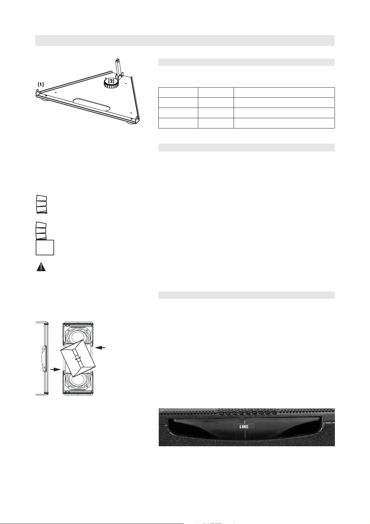
Fig. 1:Z5375 T Base plate
GROUND USE:
3 x T10 MAX.
6 x T10 MAX. WHEN
CONNECTED TO SUB
NOT FOR
FLOWN USE
Z5375 T Base plate
1. Scope of supply
Please verify the shipment for completeness and proper condition of the
items.
Qty. d&b Code Description
1 Z5375
1
1 D2999.INT Mounting instructions
2. Intended use
The Z5375 T Base plate must only be used in conjunction with d&b T10
loudspeakers as described in these mounting instructions.
Installation and setup should only be carried out by qualified and
authorized personnel observing the valid national Rules for the
Prevention of Accidents (RPA).
The Z5375 T Base plate is designed to support up to three T10 Line
array cabinets in a ground stacked setup and is equipped with three
rubber feet.
T Base plate [1]
including hand bolt M20 x 25 [2]
Fig. 2: Z5375 T Base plate, intended use
Fig. 3: Rotating the horn
(shown without front grill for better illustration)
The Z5375 T Base plate is not intended for flown use.
The angle of the lowest cabinet can be set in the range from +5° to
– 8°.
When used on top of d&b subwoofers such as Q-SUB, E15X-SUB,
B4-SUB or V-SUB, the T Base plate is secured to the subwoofer using
the M20 flange in the top panel of the subwoofer. It can then support a
column of up to six T10 cabinets.
3. Preparations
T10 cabinets
Altering the HF dispersion on T10 cabinets
When setting up T-Series arrays and ground stacks set the T10 cabinets
to line source mode.
Swapping between point and line source setups is performed by simply
rotating the horn by 90°. The horn is easily accessible from outside of
the cabinet and can be rotated without any tools or removal of the
front grill.
This is achieved through apertures on the cabinet sides by a mechanism
that provides detents at both the line and point source positions.
The line source mode is indicated by a label on the horn marked with
LINE as shown in the picture below.
Z5375 Mounting instructions (1.1 EN) Page 3 of 8
Page 4

Functionality of the cabinet's rigging mechanism
Front link mechanism
- Slide out the Front link until it is fixed in place.
Splay link mechanism
- Release both Locking pins and fold out the Splay link.
Preset splay angles on T10 cabinets
The splay angles between T10 cabinets can be set in the range from 0°
to 15° in 1° steps.
The splay angles are set at the central rear rigging strands of the T10
cabinets.
Z5375 Mounting instructions (1.1 EN) Page 4 of 8
Page 5

Interconnecting the cabinets
The T10 cabinets are interconnected by their Front links on both sides of
the cabinet front and the Splay links on the center rigging strand at the
cabinet's rear.
Front links
Once the Front links slide into the respective track of the next cabinet,
the cabinets are interconnected by inserting the Locking pins on both
sides of the cabinet.
Splay links
Fold out the Splay links of the T10 cabinets and hook them into the
preset Locking pins on the rear rigging strand of the next cabinet.
Once the Splay link is hooked in, the second Locking pin must be
inserted. The second Locking pin acts as a "safety pin" to secure the
Splay link from possible hooking off and to fix the set splay angle.
4. Setup of the assembly
WARNING!
Always secure ground stacked setups against movement and
possible tipping over.
Preparations
- Prepare the cables and link cables according to the number of
amplifier channels and cabinets used.
- Ensure the HF sections of the T10 cabinets to be used are set to Line
source.
1. Prepare the the T Base plate
T10 Groundstack
- Place the T Base plate on the ground.
T10/SUB Groundstack
- Connect the T Base plate with the M20 threaded insert of the
respective subwoofer using the M20 hand bolt.
2. Add the first cabinet
- Release the locking pins on both sides of the cabinet front.
- Attach the cabinet to the T Base plate.
- Insert the Locking pins of the Front links on both sides of the cabinet.
Z5375 Mounting instructions (1.1 EN) Page 5 of 8
Page 6

3. Set the angle of the first cabinet
The angle (vertical aiming) of the lowest cabinet can be set in the range
from +5° to –8°. The desired angle is set using the corresponding hole
of the Splay link of the Base plate and the hole grid of the rear rigging
strand of the T10 cabinet. The derived scale is shown in the graphic
opposite.
The notch at the top of the Base plate's Splay link is intended to simplify
the mechanical setup and provides a +2° offset in relation to the hole of
the link.
To set the angle proceed as follows:
- Fold out the Splay link of the cabinet.
- Lift the back of the cabinet
- Insert the first Locking pin into the corresponding hole of the rear
rigging strand of the cabinet.
Example:
To achieve a –5° downtilt of the first cabinet, insert the first Locking
pin (support pin) into the 5° hole of the cabinet.
- Fold up the Base plate's link into the rear rigging strand and lower
the cabinet's back into the notch of the link.
- Insert the second Locking pin (safety pin) into the 3° hole of the
cabinet to secure the link of the Base plate.
4. Add the next cabinet
- Slide out the Front link at bottom cabinet.
- Fold out the Splay link.
- Release the Locking pins on both sides of the cabinet front.
- Attach the cabinet to the first cabinet.
- Insert the Locking pins of the Front links on both sides of the cabinet.
To attach further cabinets, proceed in the same manner.
Z5375 Mounting instructions (1.1 EN) Page 6 of 8
Page 7

5. Set the desired splay angle
- On the rear, set the splay angles between the cabinets as follows:
- Preset the desired splay angle on the top cabinet by
inserting one Locking pin.
- Fold up the Splay link of the cabinet below into the rear
rigging strand of the upper cabinet.
- Lift the upper cabinet by hand until the hook of the Splay
link has hooked into the preset Locking pin.
- Insert the second Locking pin (safety pin) to secure the Splay
link.
5. Maintenance and care
Storing/transport
The surface treatment temporarily protects the Base plate against
moisture. However, ensure the Base plate is in a dry state when storing
and transporting it.
During transport ensure the Base plate is not stressed or damaged by
mechanical forces. Use suitable transport cases.
Cleaning
Regularly clean and lubricate the Base plate using WD-40®or a similar
product.
Inspections
To eliminate the potential risk of accident due to malfunctioning of the
Base plate, regularly carry out a visual and functional inspection.
If the Base plate fails to operate correctly and/or safely, it must be
withdrawn from use immediately.
Carry out a visual inspection of the Base plate for obvious deformation
and damage (e.g. cracks and corrosion).
6. Disposal
Please dispose of this product according to the respective national
regulations.
Ensure that damaged rigging components are disposed of so that they
cannot be used again.
Z5375 Mounting instructions (1.1 EN) Page 7 of 8
Page 8

D2999.EN .01, 12/2012 d&b audiotechnik GmbH
d&b audiotechnik GmbH, Eugen-Adolff-Str. 134, D-71522 Backnang, Germany, Phone +49-7191-9669-0, Fax +49-7191-95 00 00
 Loading...