

Page 1

Z5373
T Cluster bracket
Mounting instructions (1.0 EN)
Page 2

Contents
1. Product description..........................................................3
Scope of supply..................................................................................................3
Technical specification.......................................................................................3
2. Intended use.....................................................................4
3. Safety precautions...........................................................4
General safety....................................................................................................4
Load safety information....................................................................................4
4. Total vertical aiming........................................................5
5. Preparations.....................................................................5
T10 cabinets.........................................................................................................5
Functionality of the cabinet's rigging mechanism......................................6
Preset splay angles on T10 cabinets.............................................................6
6. Setup of the assembly.....................................................7
7. Operation.........................................................................8
Vertical alignment...............................................................................................8
Horizontal alignment.........................................................................................8
8. Maintenance and care.....................................................9
Storing/transport................................................................................................9
Cleaning................................................................................................................9
Inspections............................................................................................................9
9. Disposal............................................................................9
General Information
Z5373 T Cluster bracket
Mounting instructions
Version 1.0 EN, 01/2009, D2996.EN .01
Copyright © 2009 d&b audiotechnik GmbH; all rights reserved.
Keep this manual with the product or in a safe place so that it is
available for future reference.
d&b audiotechnik GmbH
Eugen-Adolff-Strasse 134, D-71522 Backnang, Germany
Telephone +49-7191-9669-0, Fax +49-7191-95 00 00
E-mail: docadmin@dbaudio.com, Internet: www.dbaudio.com
Page 3
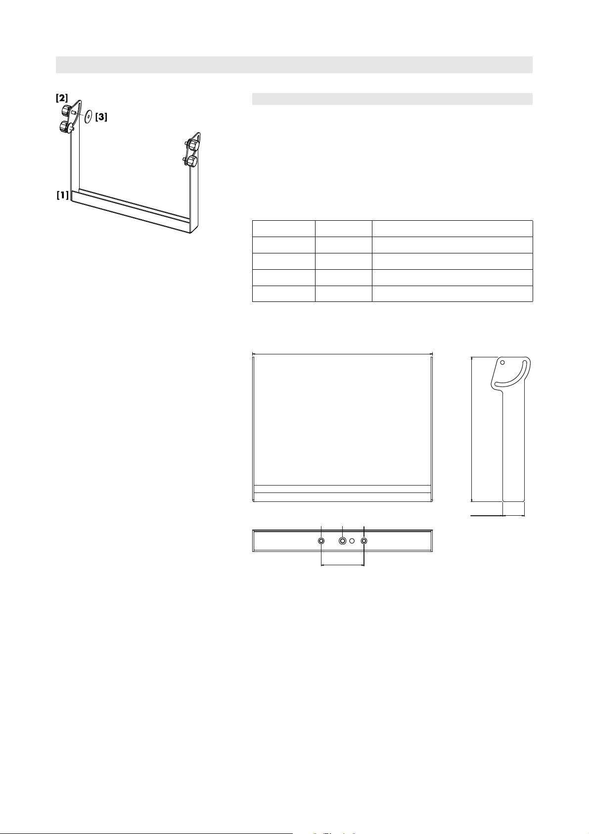
Fig. 1:Z5373 T Cluster bracket
484 [19"]
115 [4.5"]
58 [2.3"]
389 [15.3"]
M8 M8M10
Z5373 T Cluster bracket
1. Product description
The Z5373T Cluster bracket allows up to three T10 loudspeaker
cabinets to be mounted and set to different horizontal or vertical angles.
For this purpose two M8 threaded inserts at the d&b standard spacing
of 115 mm (4.5") together with a center M10 thread are integrated in
the tie bar of the bracket.
Scope of supply
Please verify the shipment for completeness and proper condition of the
items.
Qty. d&b Code Description
1 Z5373
4
4
1 D2996.INT Mounting instructions
Technical specification
Weight.............................................................................................................3.3 kg (7.3 lb)
T Cluster bracket [1]
Hand bolt M10 x 20 [2]
Rubber washer [3]
Fig. 2: Dimensions in mm [inch]
Z5373 Mounting instructions (1.0 EN) Page 3 of 10
Page 4

2. Intended use
The Z5373 T Cluster bracket must only be used in conjunction with d&b
T10 loudspeakers as described in these mounting instructions.
Installation and setup should only be carried out by qualified and
authorized personnel observing the valid national Rules for the
Prevention of Accidents (RPA).
It is the responsibility of the person installing the assembly to ensure that
the suspension/fixing points are suitable for the intended use.
The Z5024 Loudspeaker stand adapter enables the Cluster bracket to
be attached to a loudspeaker stand.
The bracket can be attached on top of maximum one d&b Q-SUB
cabinet using the Z5013 Loudspeaker stand M20 along with the Z5024
Loudspeaker stand adapter.
The bracket can be mounted to overhead bars or trusses with a tube
diameter of up to 51 mm (2") using the Z5010 TV spigot and the
Z5012 Pipe clamp.
3. Safety precautions
General safety
Always carry out a visual and functional inspection of the bracket
before use. In case you have any doubt as to the proper functioning
and safety of the bracket, do not use it. Please also refer to section 8.
Maintenance and care on page 9.
The total center of gravity of the assembly is located at the very top of
the entire assembly.
- Always secure the assembly against movement and possible tipping
over.
- Ensure no person is in the direct area around the assembly.
- When the assembly is mounted to overhead bars or trusses ensure
the secondary safety is applied.
Load safety information
The maximum permitted working load of the bracket is 33 kg (73 lb)
(according to BGV C1) which corresponds to the weight of a maximum
of three T10 loudspeakers.
NOTICE:
Always align the bracket vertically when using it, whether
it is suspended or placed on top of a loudspeaker stand.
Right Right WRONG
Observe the maximum permitted load of the additional rigging
accessories as stated in the respective mounting instructions.
Ensure the loudspeaker stand used is designed to safely support the top
load of 37 kg (81.5 lb).
Z5373 Mounting instructions (1.0 EN) Page 4 of 10
Page 5

4. Total vertical aiming
Depending on the type of application (deployed on a hi stand or
suspended) the bracket can be attached in two directions allowing the
vertical aiming of the entire assembly within a range of 105° (+15° to
-90° or +90° to -15°).
5. Preparations
T10 cabinets
Altering the HF dispersion on T10 cabinets
When setting up T-Series arrays and ground stacks set the T10 cabinets
to line source mode.
Fig. 3: Rotating the horn
(shown without front grill for better illustration)
Swapping between point and line source setups is performed by simply
rotating the horn by 90°. The horn is easily accessible from outside of
the cabinet and can be rotated without any tools or removal of the
front grill.
This is achieved through apertures on the cabinet sides by a mechanism
that provides detents at both the line and point source positions.
The line source mode is indicated by a label on the horn marked with
LINE as shown in the picture below.
Z5373 Mounting instructions (1.0 EN) Page 5 of 10
Page 6

Functionality of the cabinet's rigging mechanism
Front link mechanism
- Slide out the Front link until it is fixed in place.
Splay link mechanism
- Release both Locking pins and fold out the Splay link.
Preset splay angles on T10 cabinets
The splay angles between T10 cabinets can be set in the range from 0°
to 15° in 1° steps.
The splay angles are set at the central rear rigging strands of the T10
cabinets.
Z5373 Mounting instructions (1.0 EN) Page 6 of 10
Page 7

Interconnecting the cabinets
The T10 cabinets are interconnected with their Front links on both sides
of the cabinet front and with the Splay links on the center rigging strand
at the cabinet's rear.
Front links
Once the Front links slide into the respective track of the next cabinet,
the cabinets are interconnected by inserting the Locking pins on both
sides of the cabinet.
Splay links
Fold out the Splay links of the T10 cabinets and hook them into the
preset Locking pins on the rear rigging strand of the next cabinet.
Once the Splay link is hooked in, the second Locking pin must be
inserted. The second Locking pin acts as a "safety pin" to secure the
Splay link from possible hooking off and to fix the set splay angle.
6. Setup of the assembly
Preparations
- Prepare the cables and link cables according to the number of
amplifier channels and cabinets used.
- Ensure the HF sections of the T10 cabinets to be used are set to Line
source.
1. Prepare the first T10 cabinet
- Place the first cabinet on the ground.
- Slide out the Front link
- Fold out the Splay link.
2. Add the next cabinet
- Fold out the Splay link of the next cabinet.
- Release the Locking pins on both sides at the front of the cabinet.
- Attach the cabinet to the first cabinet.
- Insert the Locking pins of the Front links on both sides of the cabinet.
To attach a third cabinet, proceed in the same manner.
Z5373 Mounting instructions (1.0 EN) Page 7 of 10
Page 8

3. Set the desired splay angles
- On the rear, set the splay angles between the cabinets as follows:
- Starting with the top cabinet of the assembly first preset the
desired splay angle by inserting one Locking pin.
- Fold up the Splay link of the cabinet below into the rear
rigging strand of the upper cabinet.
- Lift the upper cabinet by hand until the hook of the Splay
link has hooked into the preset Locking pin.
- Insert the second Locking pin (safety pin) to secure the Splay
link.
- Proceed in the same manner until all splay angles of the cabinets are
set.
Note:
The two Locking pins at the bottom cabinet of the
assembly are not used. They should be stored in two of
the remaining holes on the rear rigging strand.
4. Attach the Cluster bracket to the assembly
- Turn over the assembly with the front grill facing the ground.
- Attach the Cluster bracket with the desired direction as follows:
3-deep 2-deep
- Fix the bracket to the M10 threaded inserts on both sides of the
cabinet using the four supplied hand bolts.
7. Operation
Once the assembly is completed and attached to its operating position,
the total vertical and horizontal aiming can be adjusted.
Vertical alignment
- Slightly slacken the four hand bolts [2] until the assembly is just about
free to be moved.
- Set the desired vertical aiming of the assembly.
- Retighten all four hand bolts to fix the total vertical angle.
Horizontal alignment
The loudspeaker is aligned horizontally via the Loudspeaker stand
adapter or the TV spigot mounting.
Z5373 Mounting instructions (1.0 EN) Page 8 of 10
Page 9

Fig. 4: Threaded inserts in the tie bar
8. Maintenance and care
Storing/transport
The surface treatment temporarily protects the Flying bracket against
moisture. However, ensure the bracket is in a dry state when storing
and transporting it.
During transport ensure the bracket is not stressed or damaged by
mechanical forces. Use suitable transport cases.
Cleaning
Regularly clean and lubricate the bracket using WD-40®or a similar
product.
Inspections
To eliminate the potential risk of accident due to malfunctioning of the
bracket, regularly carry out a visual and functional inspection of the
bracket.
If the bracket fails to operate correctly and/or safely, it must be
withdrawn from use immediately.
Carry out a visual inspection of the bracket for obvious deformation
and damage (e.g. cracks and corrosion).
Carry out a visual inspection of the weld strength and the threaded
inserts in the tie bar of the bracket for damage (e.g. cracks and
corrosion).
9. Disposal
Please dispose of this product according to the respective national
regulations.
Ensure that damaged rigging components are disposed of so that they
cannot be used again.
Z5373 Mounting instructions (1.0 EN) Page 9 of 10
Page 10

Manufacturer's declarations
EC Declaration of conformity
within the meaning of the EC Machine Directive 98/37/EEC
We hereby declare that the equipment designated below is designed and
built in the version sold by us in such a way as to comply with the
relevant fundamental safety and health criteria of the applicable EC
Directive(s). This declaration shall cease to be valid if alterations are
made to the equipment without our prior agreement.
This declarations covers:
d&b T Cluster bracket, Z5373
To be used as described in these mounting instructions.
National standards and technical specifications applied:
DIN EN ISO 12100, DIN EN 1050, BGV C1
D2996.EN .01, 01/2009 d&b audiotechnik GmbH
Backnang, 2009-01-27
(Frank Bothe, Managing director)
d&b audiotechnik GmbH, Eugen-Adolff-Str. 134, D-71522 Backnang, Germany, Phone +49-7191-9669-0, Fax +49-7191-95 00 00
 Loading...