

Page 1

Z5354
E8/E12 Flying adapter
Z5355
E8/E12 Flying adapter link
Mounting instructions (1.3 EN)
Page 2

Contents
1. Scope of supply....................................................................................................3
2. Intended use..........................................................................................................4
3. Safety precautions...............................................................................................4
4. Attaching the Flying adapter to the cabinet................................................4
5. Vertical and horizontal aiming.........................................................................5
6. Using the Flying adapter link............................................................................6
7. Maintenance and care.......................................................................................8
8. Disposal..................................................................................................................8
Manufacturer's declarations..................................................................................9
General Information
Z5354 E8/E12 Flying adapter
Z5355 E8/E12 Flying adapter link
Mounting instructions
Version 1.3 EN, 06/2015, D2978.EN .01
Copyright © 2015 d&b audiotechnik GmbH; all rights reserved.
Keep this manual with the product or in a safe place so that it is
available for future reference.
d&b audiotechnik GmbH
Eugen-Adolff-Strasse 134, D-71522 Backnang, Germany
Telephone +49-7191-9669-0, Fax +49-7191-95 00 00
E-mail: docadmin@dbaudio.com, Internet: www.dbaudio.com
Page 3
Z5354 E8/E12 Flying adapter, Z5355 E8/E12 Flying adapter link
202 [8"]
46.2 [1.8"]
85 [3.3"]
47 [1.8"]
M10
95 [3.7"]
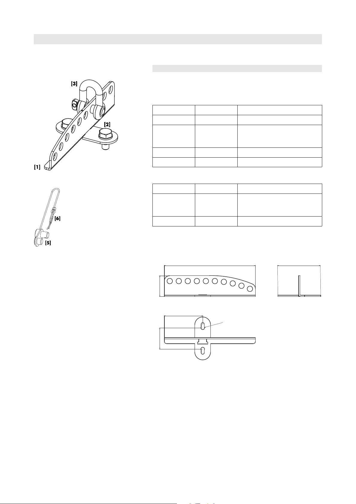
1. Scope of supply
The Flying adapter and the link are delivered separately. Please verify
the respective shipment for completeness and condition of the items.
Flying adapter
Qty. d&b Code Description
1 Z5354
2
1
1 D2978.INT Mounting instructions
E8/E12 Flying adapter [1]
Hex head bolt, M10 x 25 [2] with
spring washer (undetachably preassembled)
Shackle 1 to. [3] (pre-assembled)
Z5354, E8/E12 Flying adapter
Z5355, E8/E12 Flying adapter link
Flying adapter link
Qty. d&b Code Description
1 Z5355
1 D2978.INT Mounting instructions
E8/E12 Flying adapter link [5] with
securing pin [6] that is attached to the
link by a steel wire.
Z5354, E8/E12 Flying adapter dimensions in mm [inch]
Z5354/Z5355, Mounting instructions (1.3 EN) Page 3 of 10
Page 4

2. Intended use
The Z5354, E8/E12 Flying adapter and the Z5355 E8/E12 Flying
adapter link must only be used in conjunction with the d&b E-Series E8
and E12 (E12-D), T-Series T(i)10 (in Point source mode) or Y-Series
Y(i)7P/Y(i)10P loudspeakers as described in these mounting instructions.
Installation and setup should only be carried out by qualified and
authorized personnel observing the valid national Rules for the
Prevention of Accidents (RPA).
It is the responsibility of the person installing the assembly to ensure that
the suspension/fixing points are suitable for the intended use.
The Flying adapter can be used:
– together with the supplied 1 to. Shackle to be suspended using
a steel wire rope or chain.
– together with the Z5015 TV spigot and Z5012 Pipe clamp to
be attached to overhead bars or trusses with a tube diameter
up to 51 mm (2”).
Alternatively the Z5147 Rota Clamp can be used.
– together with the Z5355, E8/E12 Flying adapter link to set up
a vertical array of maximum of two cabinets.
Application example E12/E12-D
NOTICE:
Observe the maximum permitted load of the related
accessories as stated in the respective manuals/mounting
instructions.
3. Safety precautions
General safety
Always carry out a visual and functional inspection of the components
before use. If there is any doubt as to the function and safety of the
components, do not use them. Please also refer to section
7. Maintenance and care on page 8.
Load safety information
The maximum permitted working load of the adapter corresponds to a
weight of max. two loudspeakers listed above, to be flown one below
the other.
4. Attaching the Flying adapter to the cabinet
The Flying adapter can be attached in two directions (1 and 2 - as
shown in the graphic opposite) and is directly bolted to the M10
threaded inserts of the cabinet's top or bottom panel.
Tools required: Open ended spanner/wrench (size #17).
1. Attach the Flying adapter to the threaded inserts of the cabinet.
2. Screw in the two hex head bolts until they are hand tightened.
3. Finally tighten the screws.
Z5354/Z5355, Mounting instructions (1.3 EN) Page 4 of 10
Page 5

Direction1 Vertical aiming
E8
Hole grid 1 2 3 4 5 6 7 8 9 10
Angle (°)*
E12 (E12-D)
Hole grid 1 2 3 4 5 6 7 8 9 10
Angle (°)*
T10 (in Point Source Mode)
5. Vertical and horizontal aiming
Vertical aiming
The Flying adapter is equipped with ten locating holes (12 mm). The
vertical aiming of the loudspeaker depends on which of the adapter's
locating holes is used. The vertical angle is related to the center of
gravity of the cabinet.
The Flying adapter can be attached in two directions. The corresponding
values for a single cabinet are listed in the following tables for both
directions of the Flying adapter.
+6 0 –5 –11 –16 –21 –26 –31 –36 –40
–6 –9 –13 –16 –20 –23 –26 –29 –33 –36
Hole grid 1 2 3 4 5 6 7 8 9 10
Angle (°)*
+8 +4 –1 –5 –10 –14 –18 –23 –27 –31
10S/D
Hole grid 1 2 3 4 5 6 7 8 9 10
Angle (°)*
+17.5 +14 +11 +7.5 +4.5 +1 –2.5 –6 –9 –12.5
12S/D
Hole grid 1 2 3 4 5 6 7 8 9 10
Angle (°)*
+23 +19.5 +16.5 +13 +9.5 +6.5 +3 0 –3.5 –6.5
Y(i)7P/Y(i)10P
Hole grid 1 2 3 4 5 6 7 8 9 10
Angle (°)*
* Positive value: Cabinet points upwards. Negative value: Cabinet points downwards
+7.5 +4 +0.5 –3.5 –7 –11 –14.5 –18 -22 –25
Z5354/Z5355, Mounting instructions (1.3 EN) Page 5 of 10
Page 6

Direction 2 Vertical aiming
25°
E8
Hole grid 1 2 3 4 5 6 7 8 9 10
Angle (°)*
E12 (E12-D)
Hole grid 1 2 3 4 5 6 7 8 9 10
Angle (°)*
T10 (in Point Source Mode)
Hole grid 1 2 3 4 5 6 7 8 9 10
Angle (°)*
10S/D
Hole grid 1 2 3 4 5 6 7 8 9 10
Angle (°)*
12S/D
Hole grid 1 2 3 4 5 6 7 8 9 10
Angle (°)*
+16 +10 +4 –1 –7 –12 –18 –22 –27 –32
0 –3 –6 –10 –13 –17 –20 –24 –27 –30
0 –3 –6 –10 –13 –17 –20 –24 –27 –30
+10.5 +7 +4.5 +1.5 –2.5 –5 –8.5 –11.5 –14.5 –17.5
+15.5 +12 +9 +6 +3.5 +0.5 –3.5 –6 –9.5 –12
Y(i)7P/Y(i)10P
Hole grid 1 2 3 4 5 6 7 8 9 10
Angle (°)*
* Positive value: Cabinet points upwards. Negative value: Cabinet points downwards
+14 +10 +6.5 +2.5 +1 –5 –8.5 –12 –15.5 –25
Note on T10 cabinets
Due to the narrow vertical dispersion angle of 35° of the T10 cabinet in
point source mode, we recommend a maximum splay angle of 25°
between two vertically flown T10 cabinets.
To achieve this, insert the Flying adapter link to hole 7/8 with the Flying
adapter attached in direction 1.
The use of the Flying adapter link is described in the following section 6.
Horizontal aiming
The horizontal aiming of the entire array is adjusted at the suspension
point or lifting device .
6. Using the Flying adapter link
The Z5355 E8/E12 Flying adapter link enables two Flying adapters to
be linked together. This allows E8, E12 (E12-D), T(i)10 or Y(i)7P/Y(i)10P
cabinets to be arrayed vertically.
The link is equipped with a securing pin (Rue ring cotter) which is
attached to the link by a steel wire. The pin is used to secure the link.
Z5354/Z5355, Mounting instructions (1.3 EN) Page 6 of 10
Page 7

Function of the securing pin (Rue ring cotter)
Assembly
Step 1 and 2 Step 3
CAUTION!
Carry out the entire assembly on stable ground before
lifting the array into its operating position.
Preparing the loudspeaker
(Graphic opposite: step 1 and 2)
For acoustical reasons we recommend to attach the two Flying adapters
between the cabinets in the same direction.
1. Attach one Flying adapter each to the top and bottom panel of the
upper loudspeaker.
2. Attach one Flying adapter to the top panel of the second
loudspeaker.
Link the Flying adapters together
(Graphics opposite: step 3 to 5)
3. Position the bottom Flying adapter of the upper cabinet with the
Flying adapter of the bottom cabinet so that two of the locating
holes are aligned.
4. From one side attach the link to the two holes which are in line.
5. Attach the securing pin.
CAUTION!
Ensure the securing pin is properly attached before
lifting the array into its operating position.
Properly attached securing pin
Step 4 and 5
Z5354/Z5355, Mounting instructions (1.3 EN) Page 7 of 10
Page 8

7. Maintenance and care
Storing/Transport
Due to its surface treatment the components are temporarily protected
against moisture. However, ensure the components are in a dry state
while stored or during transport and use.
During transport ensure the components are not stressed or damaged
by mechanical forces.
Cleaning
Regularly clean and lubricate the components using an anti-corrosion
agent.
Inspections
To eliminate the potential risk of accident due to malfunctioning of the
components carry out a visual and functional inspection of the
components regularly.
If the components fail to operate correctly and/or safely the bracket
must be withdrawn from use immediately.
Flying adapter and link
In particular pay attention to obvious damage, deformation, cracks and
corrosion.
Securing pin (Rue ring cotter)
Visually inspect the securing pin for obvious damage and deformation.
Also carry out a functional test of the locking mechanism.
Securing pin o.k. Change the securing pin
Condition of the securing pin
If it is no longer possible to fit and lock the securing pin, it must be
replaced (refer to the graphic opposite).
d&b order code: Q9083 (Securing pin RUE 22).
8. Disposal
Please dispose of this product according to the respective national
regulations.
Ensure that damaged rigging components are disposed of in a way that
they can not be used again.
Z5354/Z5355, Mounting instructions (1.3 EN) Page 8 of 10
Page 9

Manufacturer's declarations
EC Declaration of conformity
within the meaning of the EC Machine Directive 98/37/EEC
We hereby declare that the equipment designated below is designed and built in the version sold by us in such a way as
to comply with the relevant fundamental safety and health criteria of the applicable EC Directive(s). This declaration shall
cease to be valid if alterations are made to the equipment without our prior agreement.
This declarations covers:
d&b E8/E12 Flying adapter, Z5354
d&b E8/E12 Flying adapter link, Z5355
To be used as described in these mounting instructions.
National standards and technical specifications applied:
DIN EN ISO 12100, DIN EN 1050, BGV C1
Backnang, January 10, 2008
(Frank Bothe, Head of R&D)
d&b audiotechnik GmbH, Eugen-Adolff-Str. 134, D-71522 Backnang, Germany, Phone +49-7191-9669-0, Fax +49-7191-95 00 00_______
Page 10

D2978.EN .01, 06/2015 d&b audiotechnik GmbH
d&b audiotechnik GmbH, Eugen-Adolff-Str. 134, D-71522 Backnang, Germany, Phone +49-7191-9669-0, Fax +49-7191-95 00 00_______
 Loading...