

Page 1

Z5147
Rota Clamp
Mounting instructions (2.2 EN)
Page 2

Contents
1. Product description..............................................................................................3
2. Scope of supply....................................................................................................3
3. Load safety information.....................................................................................3
4. Weight/Installation height.................................................................................3
5. Assembly................................................................................................................3
6. Installation..............................................................................................................4
7. Operation/Adjustments.....................................................................................6
8. Maintenance and care.......................................................................................7
9. Disposal/Environmental protection.................................................................7
10. Manufacturrer's declaration..........................................................................8
General information
Z5147 Rota Clamp
Mounting instructions
Version 2.2 EN, 03/2013, D2970.EN .02
Copyright © 2013 d&b audiotechnik GmbH; alll rights reserved.
Keep this manual with the product or in a safe place
so that it is available for future reference.
d&b audiotechnik GmbH
Eugen-Adolff-Strasse 134, D-71522 Backnang
Telefon: +49-7191-9669-0, Fax: +49-7191-95 00 00
E-mail: docadmin@dbaudio.com, Internet: www.dbaudio.com
Page 3
Z5147 Rota Clamp
Ø
30
Ø
50
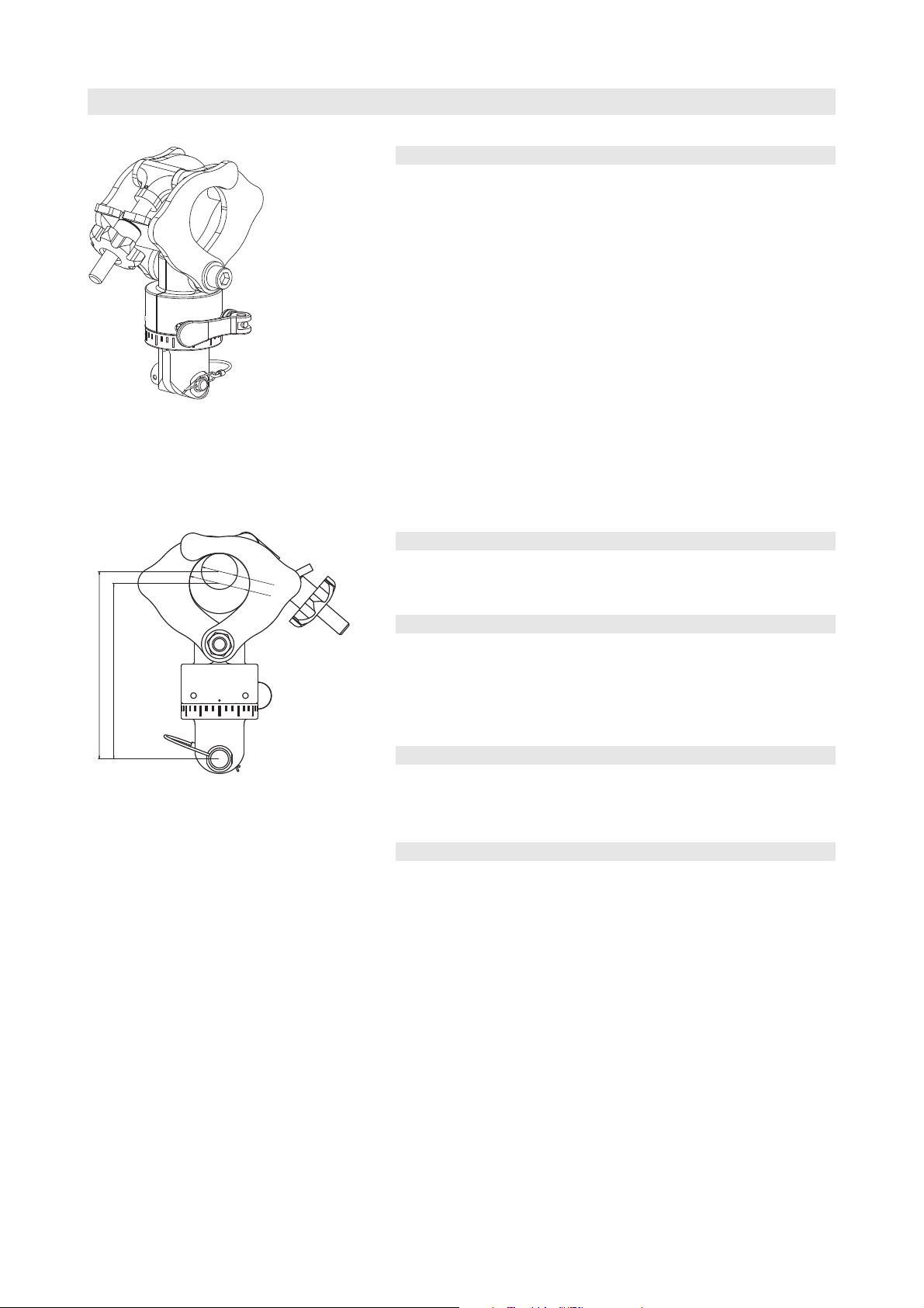
1. Product description
Using the Z5147 Rota Clamp loudspeaker arrays or single cabinets can
be suspended and horizontally aligned from a single flying point. The
Rota Clamp allows the load to be attached to overhead bars or truss
with a tube diameter up to 51 mm (2”). It can be used in combination
with the following d&b rigging accessories:
Z5020 Flying adapter 02
Z5121/22 Flying frame 02 90°/60°
Z5044 Bracket connector
Z5145 Ci Mounting frame
Fig. 1: Z5147 Rota Clamp
Fig. 2: Z5147 Rota Clamp
Installation height
Z5054 Ci Flying adapter
Z5156 Q Flying adapter
Z5159 Q Flying frame
Observe the maximum permitted load of the respective accessories as
stated in their respective manuals/mounting instructions.
2. Scope of supply
The Z5147 Rota Clamp is pre assembled and supplied together with this
mounting instructions.
3. Load safety information
The maximum permitted load of the Z5147 Rota Clamp
is 500 kg/1100 lb according to the German standard
BGV C1. No additional loads must be added.
Never fit the clamp at an angle other than straight down.
4. Weight/Installation height
Weight..............................................................................................................2.2 kg/4.9 lb
Installation height.........155.4 mm/6", related to a tube diameter of 30 mm/1.2"
..........................................145.4 mm/5.7", related to a tube diameter of 50 mm/2"
5. Assembly
Safety precautions
The Z5147 Rota Clamp must only be used to suspend d&b loudspeaker
cabinets from a single suspension point in conjunction with the
recommended d&b rigging accessories.
Installation should only be carried out by fully trained personnel. There
are certain rules for installation that must be complied with.
It is the responsibility of the person installing the assembly to ensure that
the structure being attached to is suitable for the intended use.
All system components must be inspected for faults before use. Please
pay attention to section 8. Maintenance and care on page 7. Damaged
components must be withdrawn from use immediately.
Z5147 Mounting instructions (2.2 EN) Page 3 of 8
Page 4

Preparations
Release Remove/
Fit
Snap in Lock
[1 b ]
[1 a]
[1 a ]
The desired position in the rigg as well as the total vertical angle of the
assembly should be defined in advance. The total vertical angle can be
set via the holes grid of the respective adapter or frame.
Function of the securing pin (Rue ring cotter)
Fig. 3: Function of the Rue ring cotter (schematic diagram)
Fitting to Flying adapter/Flying frame
1. Unlock and remove the ring cotter [1a] of the fixing bolt and
remove the fixing bolt [1b].
2. Attach the Rota Clamp to the respective hole of the flying adapter
or flying frame.
Fig. 4: Z5147 Rota Clamp assembly with
Z5156 Q Flying adapter
Fig. 5: Fixing bolt secured
CAUTION!
3. Insert the fixing bolt [1b] and secure the bolt with the ring cotter
[1a].
4. Recheck your work and ensure the ring cotter [1a] is properly fitted
to the fixing bolt - Fig. 5.
6. Installation
Installation must only be to horizontal tubes. Never fit
the clamp at an angle other than straight down.
With the Rota Clamp fitted to the assembly as described above, the
assembled unit is now ready to install.
Proceed as follows:
Z5147 Mounting instructions (2.2 EN) Page 4 of 8
Page 5

[2]
Fig. 6: Installation - Step 1
[U]
[2]
Fig. 7: Installation - Step 2/3
1 First release the hand wheel [2] of the clamping lever until its end-
position.
2. Fold out the clamping lever.
3. With the support clamp open, the assembly can now be lifted into
position.
4. Close The two halves of the clamp around the bar.
Fig. 8: Installation - Step 4
Fig. 9: Installation - Step 5/6
Fig. 10: Installation - Step 7
5. Pull back the U-washer [U] of the clamping lever to the hand wheel
[2].
6. Fold back the clamping lever.
7. Hand-tighten the hand wheel [2].
Safety precaution!
No other adjustments should be attempted until the
hand wheel has been tightened.
A safety wire (secondary safety) should now be fitted to
secure the assembly before carrying out either positional
or directional adjustments.
Z5147 Mounting instructions (2.2 EN) Page 5 of 8
Page 6

7. Operation/Adjustments
[2]
[3]
0° 10°10°20° 20°30° ...... 30°
WARNING!
Fig. 11: Horizontal position
CAUTION!
Carry out positional and directional adjustments one at a
time. Never try to make more than one adjustment
without the others being firmly locked off.
Vertical alignment
The vertical tilt of the load must not be adjusted by
turning the Rota Clamp against the supporting tube. The
desired total vertical angle is to be set via the holes grid
of the respective adapter or frame in advance as
described above in section 'Assembly'.
Positional adjustment (Horizontal position)
If an adjustment of the position on the bar is necessary proceed as
follows:
1. Release the locking hand wheel [2] only enough to release the grip
on the bar.
2. While supporting the weight of the assembly, the positional
adjustment can now be made. Observe that you do not damage the
tube (notching).
3. Always re-tighten the hand wheel after any adjustments.
Horizontal alignment
Fig. 12: Z5147 Rota Clamp Horizontal
alignment
Horizontal adjustments can be carried out via the rotatable unit of the
clamp. Proceed as follows:
1. Release the excentric lever [3] of the clamp-
2. Set the desired horizontal angle.
The angle can be read from the scale releated to the mark (point) of
the clamp.
The scale's increment is 10° for every graduation mark. The taller
mark displays an increment of 30°.
3. Close the excentric lever [3].
Z5147 Mounting instructions (2.2 EN) Page 6 of 8
Page 7

[4]
[3]
[2]
[1b]
[1a]
Fig. 13:Z5147 Rota Clamp
[4a]
[4]
Maintenance and care
8. Maintenance and care
Cleaning
Regularly clean and lubricate the Rota Clamp with WD-40®or a similar
product.
Inspections
To eliminate the potential risk of accident because of malfunction of a
component regularly inspection according to the appropriate
regulations for lifting device of all system components is essential.
Test recommendations
1. Visual inspection of the Rota Clamp regarding obvious deformation
and damage (e.g. cracks and corrosion) of the components including
all holes of the components.
2. Visual inspection of the fixing bolt [1b] regarding deformation
(notching) and damage (e.g. cracks and corrosion).
3. Visual inspection of the fasting lever and hand wheel [2] regarding
deformation and damage (e.g. cracks and corrosion) and inspection
of proper function.
4. Functional inspection of the excentric lever and rotation device
(swivel mechanism for horizontal adjustment) of the clamp [3].
5. The connection between the clamp and the rotation device [4] is
adjusted for proper function by the manufacturer. A visual inspection
of the self-locking nut for correct function and an inspection of the
clamp mechanism should be carried out regularly. In the case of
damage or no proper function (e.g. twisted clamps or rough running
mechanism of the clamp) the Rota Clamp should only be repaired by
d&b audiotechnik.
Fig. 14:Z5147 Rota Clamp Deformation of
the outer clamp
Ring cotter o.k. Change the ring cotter
Fig. 15: Condition of the Rue ring cotter [1a]
6. Open the clamp mechanism and check the outer clamps for obvious
deformation - Fig. 14. In the case of damage or no proper function
(e.g. twisted clamps or rough running mechanism of the clamp) the
Rota Clamp should only be repaired by d&b audiotechnik.
7. Visual inspection of the Rue ring cotter [1a] for obvious damage and
deformation. Also carry out a functional test of the locking
mechanism. If the ring cotter can no more be properly fitted to the
fixing bolt and locked it must be exchanged - Fig. 15.
9. Disposal/Environmental protection
The product must be disposed in accordance to the national
environmental regulations.
Z5147 Mounting instructions (2.2 EN) Page 7 of 8
Page 8

Manufacturer's declaration
_______
10. Manufacturrer's declaration
We hereby declare that the equipment designated below is designed and built in the version sold by us in such a way as
to comply with the relevant fundamental safety and health criteria of the applicable EC Directive(s). This declaration shall
cease to be valid if alterations are made to the equipment without our prior agreement.
This declarations covers:
•••• Z5147 Rota Clamp
To be used as described in this mounting instructions
National standards and technical specifications applied, in particular:
DIN 18800-1, DIN EN 1050, DIN EN ISO 12100
Backnang, 2013-03-27
D2970.EN .02, 03/2013 d&b audiotechnik GmbH
(Frank Bothe, Head of R&D)
d&b audiotechnik GmbH, Eugen-Adolff-Str. 134, D-71522 Backnang, Germany, Phone +49-7191-9669-0, Fax +49-7191-95 00 00
 Loading...