

Page 1
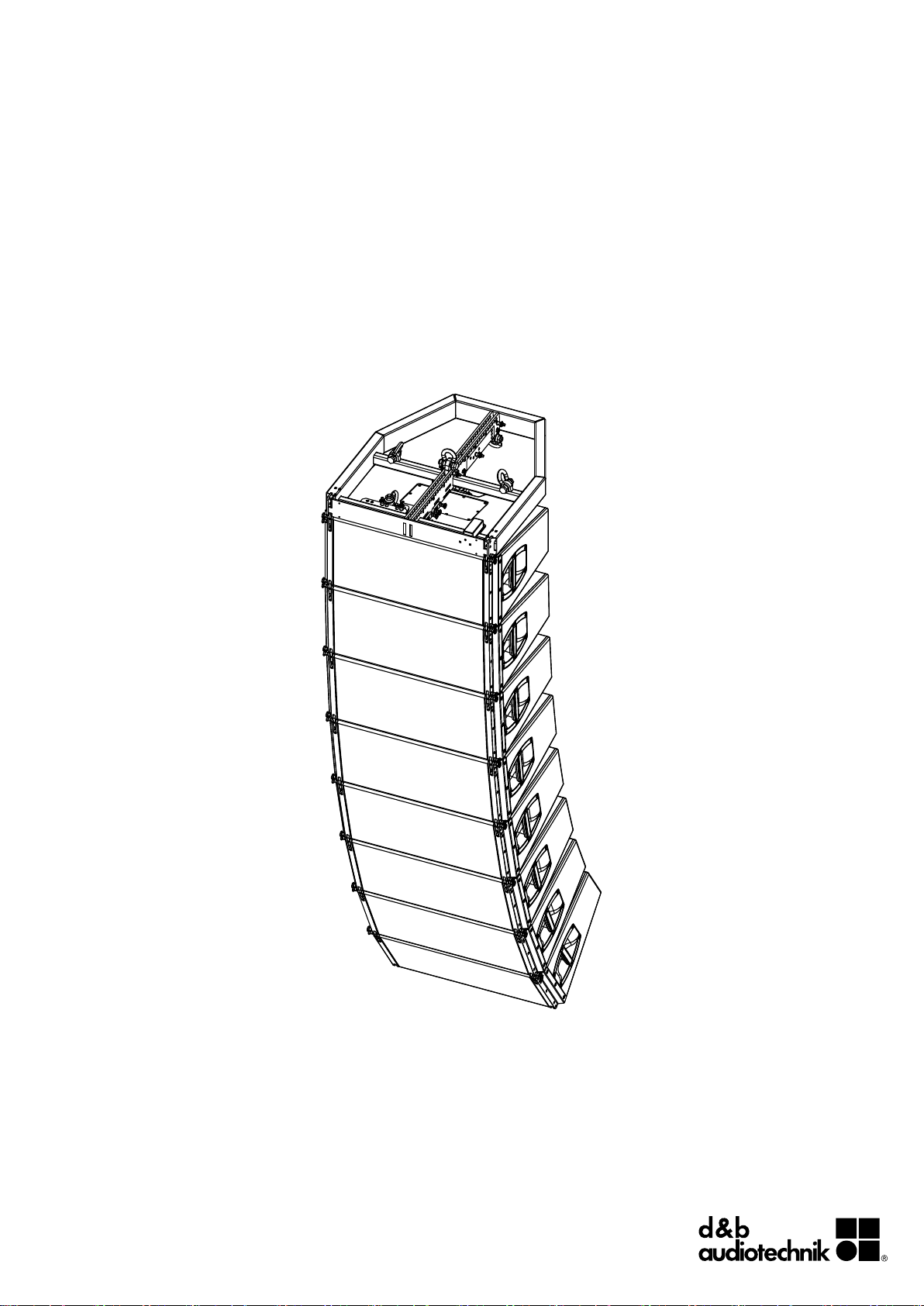
V-Series
Rigging manual (1.9 EN)
Page 2

General information
V-Series
Rigging manual
Version: 1.9 EN, 11/2014, D2702.EN .01
Copyright © 2014 by d&b audiotechnik GmbH; all rights
reserved.
Keep this manual with the product or in a safe place
so that it is available for future reference.
When reselling this product, hand over this manual to the new
customer.
If you supply d&b products, please draw the attention of your
customers to this manual. Enclose the relevant manuals with the
systems. If you require additional manuals for this purpose, you
can order them from d&b.
d&b audiotechnik GmbH
Eugen-Adolff-Strasse 134, D-71522 Backnang, Germany
T +49-7191-9669-0, F +49-7191-95 00 00
docadmin@dbaudio.com, www.dbaudio.com
Page 3

Contents
1. Safety.................................................................................... 4
1.1. Intended use............................................................................ 4
1.2. General safety......................................................................... 4
1.3. Load capacity/System safety................................................. 4
1.4. Wind loads.............................................................................. 4
1.5. d&b ArrayCalc simulation software / TI 385....................... 5
1.6. Operational safety.................................................................. 5
2. V-Series rigging concept................................................ 6
2.1.
Z5380 V Flying frame - Scope of supply.............................. 6
2.2. Z5382 V Safety chainset..................................................... 10
2.3. Z5381 V Hoist connector chain option............................... 10
2.4. Ring cotters............................................................................ 11
2.5. Locking pins........................................................................... 12
2.6. Load adapter........................................................................ 13
2.7. Suspension of the Flying frame............................................ 14
2.8. Secondary safety.................................................................. 16
2.9. Splay link of the frame.......................................................... 17
2.10. Cable pick........................................................................... 18
2.11. Cabinet rigging mechanism............................................... 19
3. V-Series arrays and assembly................................. 21
3.1.
Setup preparation................................................................. 22
3.2. Flown arrays.......................................................................... 22
3.3. V Touring cart assembly....................................................... 30
3.4. Ground stacks....................................................................... 35
4. Safety and system checks.......................................... 39
Mechanical setup................................................................. 39
4.1.
4.2. Wiring.................................................................................... 39
5. Hoisting and securing the array.............................. 40
Hoisting the array................................................................. 40
5.1.
5.2. Securing the array................................................................ 40
6. Derigging.......................................................................... 41
General................................................................................. 41
6.1.
6.2. Touring cart disassembly...................................................... 41
7. Care and maintenance / Disposal.......................... 43
Transport / Storing............................................................... 43
7.1.
7.2. Visual and functional inspection.......................................... 43
7.3. Disposal................................................................................. 44
8. Manufacturer's declaration....................................... 45
d&b V-Series Rigging manual (1.9 EN) 3
Page 4

1. Safety
1.1. Intended use
The V-Series rigging components (Flying frame, Load adapter,
Locking pins) must only be used in conjunction with d&b V-Series
loudspeakers as described in this manual.
1.2. General safety
Installation and setup should only be carried out by qualified and
authorized personnel observing the valid national Rules for the
Prevention of Accidents (RPA).
It is the responsibility of the person installing the assembly to ensure
that the suspension/fixing points are suitable for the intended use.
Always carry out a visual and functional inspection of the items
before use. In case there is any doubt as to the proper functioning
and safety of the items, these must be withdrawn from use
immediately.
Please also refer to Þ Chapter 7. "Care and maintenance /
Disposal" on page 43.
1.3. Load capacity/System safety
NOTICE!
The Z5380 V Flying frame is designed to suspend a total of 24 x
V-TOP cabinets which corresponds to a total system weight of
860 kg (1896 lb) – SWL.
The rigging components allow arrays of up to 10 x V-TOP cabinets
with a total system weight of 340 kg (750 lb) to be flown in any
vertical splay angle configuration between the cabinets.
For any other array configuration the load conditions within the
array have to be checked using the d&b ArrayCalc simulation
software.
1.4. Wind loads
WARNING!
Potential risk of personal injury and material
damage!
Flying loudspeakers overhead at wind forces higher than 6 bft
(22-27 knots, 39-49 km/h, 25-31 mph) is not recommended.
If the wind force exceeds 8 bft (34-40 knots, 62-74 km/h,
39-46 mph):
– Make sure that no person remains in the vicinity of the array.
– Lower and secure the array.
d&b V-Series Rigging manual (1.9 EN)4
Page 5
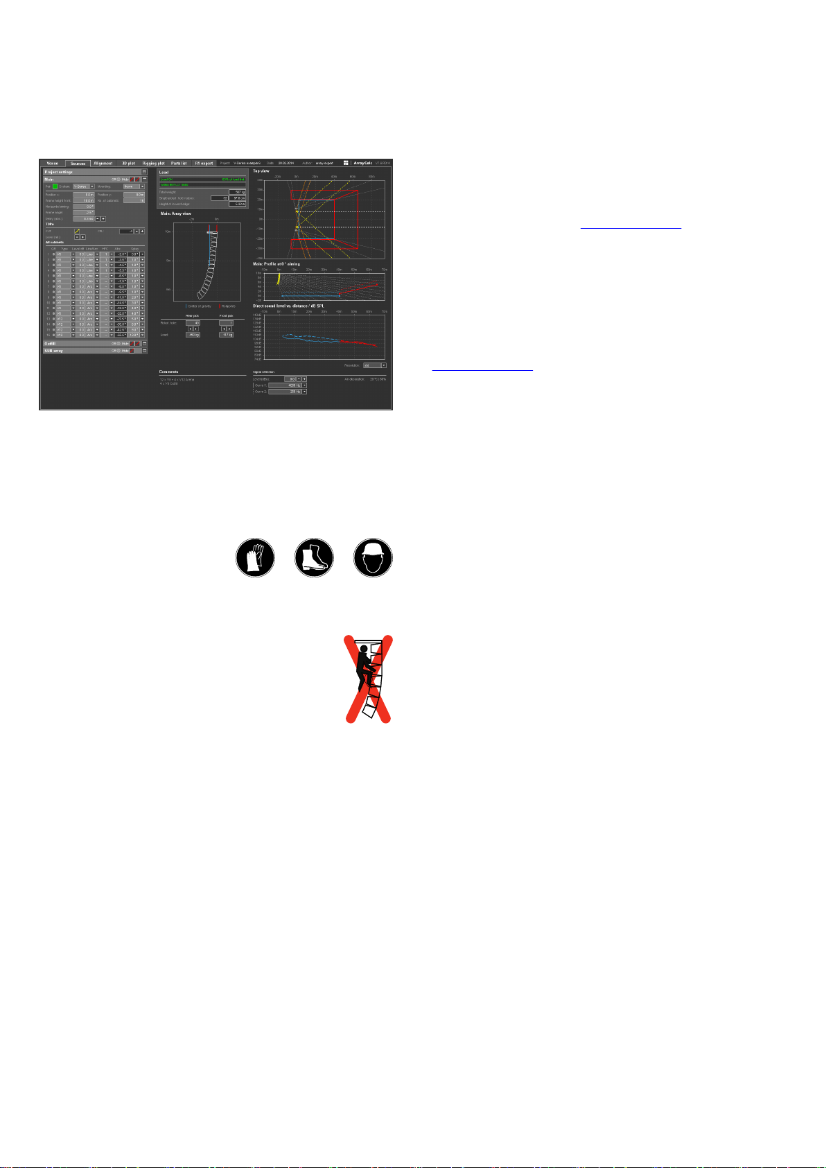
d&b ArrayCalc
1.5. d&b ArrayCalc simulation software / TI 385
For both acoustic and safety reasons d&b line arrays must be
designed using the d&b ArrayCalc simulation tool. It is available as
a native stand-alone application for both Microsoft Windows (XP
or higher) and Mac OS X (10.4.10 or higher) operating systems
and can be downloaded at www.dbaudio.com.
The use of ArrayCalc is described in "TI 385 d&b Line array
design, ArrayCalc" which is also supplied with the . This TI includes
typical array configurations within the permitted load limits.
Carefully read this TI to become familiar with the operation and
behavior of ArrayCalc and in particular with the mechanical load
conditions and limitations.
The TI can be downloaded from the d&b website at
www.dbaudio.com.
We also recommend you to attend the regularly hosted d&b Line
array training seminars. Further information regarding the d&b
seminars can be requested directly from d&b audiotechnik sales
partners.
1.6. Operational safety
The assembly should always be carried out by two persons.
During assembly pay attention to the possible risk of crushing.
Wear suitable protective clothing.
Observe all instructions given on the respective instruction labels of
the rigging components (Flying frame, Load adapters), Touring
carts and loudspeaker cabinets.
When chain hoists are in operation ensure that there is nobody
directly underneath or in the vicinity of the load.
Do not under any circumstances climb on the array.
d&b V-Series Rigging manual (1.9 EN) 5
Page 6
2. V-Series rigging concept
2.1. Z5380 V Flying frame - Scope of supply
Please verify the shipment for completeness and proper condition
of the items.
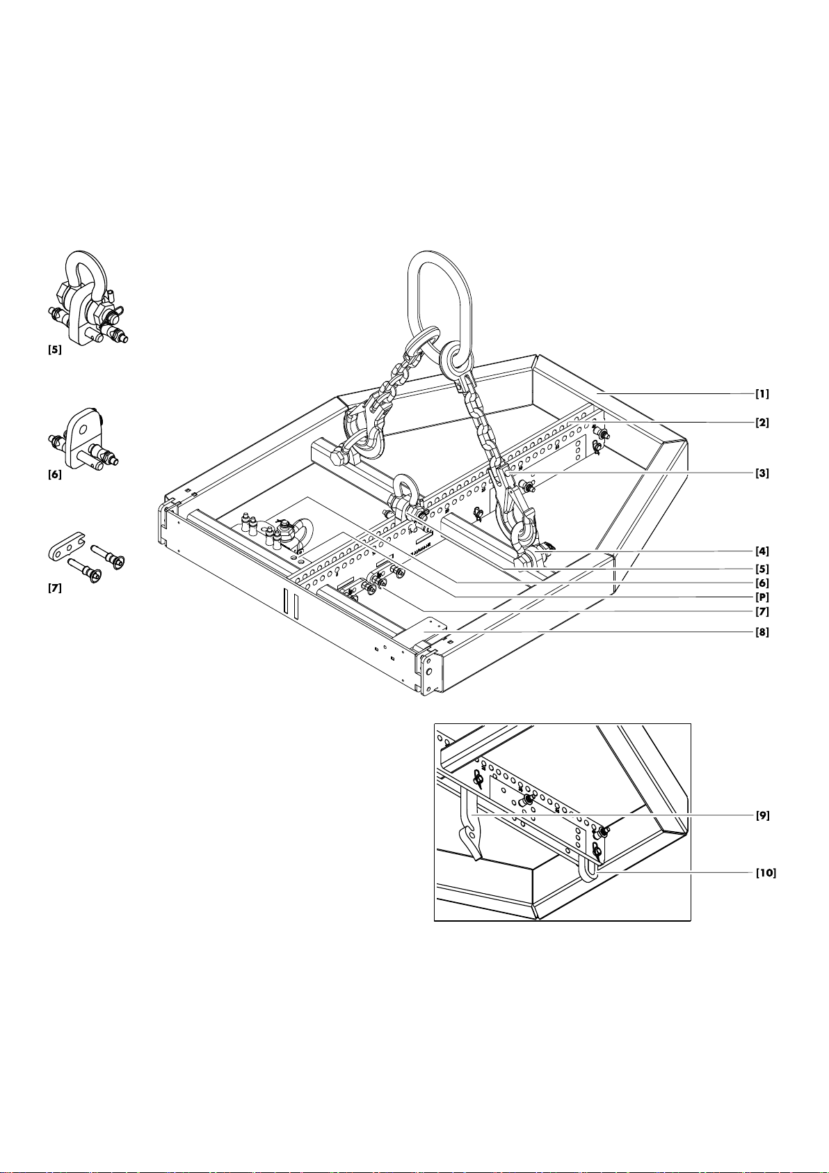
The Z5380 V Flying frame is equipped and supplied with the
following rigging components:
Z5380 V Flying frame top and bottom views
d&b V-Series Rigging manual (1.9 EN)6
Page 7

Pos. Component Description
[1]
Z5380 V Flying frame
[2]
Flying frame center bar
The Z5380 V Flying frame is designed to support arrays consisting of:
– Z0515/Z0516, V8/V12. Weight: 34 kg (75 lb).
– Z0518 V-SUB. Weight: 64 kg (141 lb).
The weight of the V Flying frame including all rigging components is 25.4 kg (56 lb).
[3]
Z5382 V Safety chainset
[4]
Safety point(s)
The Z5382 V Safety chainset is supplied with the Flying frame.
The Flying frame is fitted with two safety points each equipped with a 2 t shackle to attach a
secondary safety device using the enclosed V Safety chainset (refer to Þ Chapter 2.8.
"Secondary safety" on page 16).
[5] V Load adapter The Flying frame is supplied with two Load adapter to allow single or dual pickpoint
operation. Each Load adapter is supplied with a pair of Locking pins 10 mm and a 2 t shackle
(refer to Þ Chapter 2.6. "Load adapter" on page 13).
[6] V Load adapter Rota Clamp In addition, the enclosed V Load adapter Rota Clamp allows single pickpoint operation in
combination with the d&b Z5147 Rota clamp for a maximum system weight of up to 500 kg/
1100 lb (also refer to Þ Chapter 2.6. "Load adapter" on page 13).
[P] Park position During transport the Load adapters should be stored at their park positions (refer to
Þ Chapter 2.6. " Load adapter" Þ " Fixing the Load adapter at Park position" on page
13).
[7] Front link (Frame) Two additional Front links together with a pair of Locking pins 8 mm each are supplied with
the Flying frame. They are used to mount V-Series cabinets on top of the Flying frame for the
following setups:
– Mixed V-Series array with V-SUB cabinets at the top of the column (refer to
Þ Chapter 3.2.3. "Mixed array" on page 28).
– V-Series ground stack with the Flying frame as ground support (refer to Þ Chapter 3.4.
"Ground stacks" on page 35).
[8] Mounting plate An additional mounting plate is provided to accept industry standard inclinometers such as the
Teqsas LAP-TEQ line array positioning tool.
[9] Splay link (Frame) In connection with the Front links of the V-Series loudspeaker cabinets, the Splay link of the
frame is used to attach the first cabinet to the frame. By default, the Splay link of the frame is
fixed at «POSITION V8/V12». To accept V-SUB cabinets, the Splay link can be moved to
«POSITION V-SUB» (refer to Þ Chapter 2.9. "Splay link of the frame" on page 17).
During transport the Splay link should be folded back into its park position and secured by the
respective Locking pin.
[10] Cable pick An O-ring at the rear bottom of the frame slides out when releasing the respective Locking pin
to attach a cable pick (refer to Þ Chapter 2.10. "Cable pick" on page 18).
d&b V-Series Rigging manual (1.9 EN) 7
Page 8
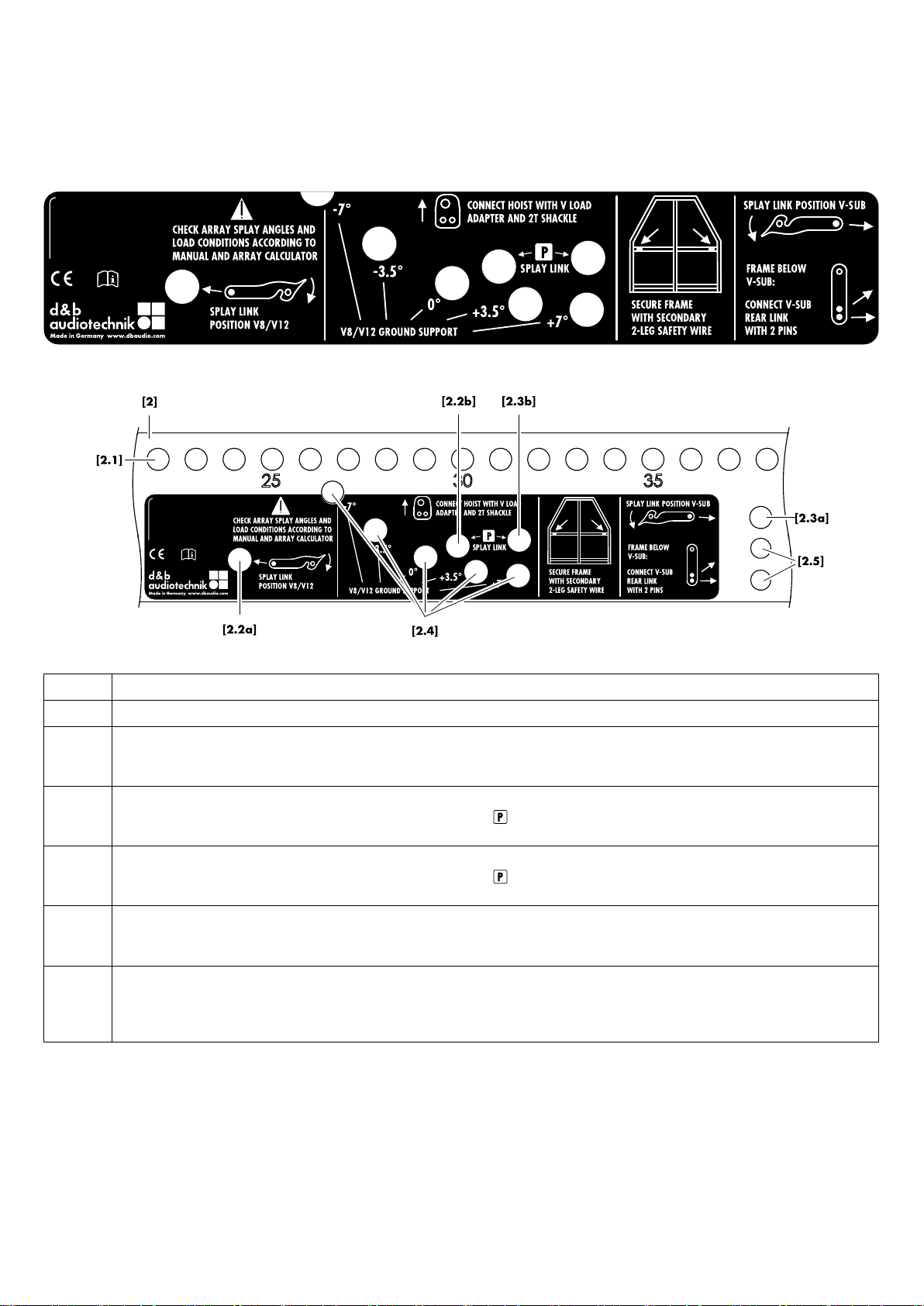
2.1.1. Flying frame instruction label
Pos. Description
[2] Center bar of the Flying frame with user instruction label.
[2.1] Main hole grid at the top of the center bar with a total of 40 holes numbered with an increment of five. Using the V Load
adapters the Flying frame can be suspended from one or two pickpoints (refer to Þ Chapter 2.6. "Load adapter" on page 13
and Þ Chapter 2.7. "Suspension of the Flying frame" on page 14).
[2.2a]
[2.2b]
Fixing point for the frame's Splay link in «POSITION V8/V12».
The additional hole is used to fix the Splay link at park position ( ) using the respective Locking pin (refer to Þ Chapter 2.9.
"Splay link of the frame" on page 17).
[2.3a]
[2.3b]
Fixing point for the frame's Splay link in «POSITION V-SUB».
The additional hole is used to fix the Splay link at park position ( ) using the respective Locking pin (refer to Þ Chapter 2.9.
"Splay link of the frame" on page 17).
[2.4] Hole grid ground stack: when V8/V12 cabinets are attached to the top of the frame, this hole grid indicates the possible settings
of –7°, –3.5°, 0°, +3.5° or +7° for the Splay link of the first (bottom) cabinet (refer to Þ Chapter 3.4. "Ground stacks"
on page 35).
[2.5] If the Flying frame is fitted below a V-SUB cabinet (Mixed V-Series array with V-SUB cabinets at the top of the column), these two
holes are used to fix the Rear link of the "last" V-SUB cabinet to the frame using the Locking pin of the respective cabinet and the
Locking pin of the Cable pick (refer to Þ Chapter 3.2.3. " Mixed array", Þ step " 2. Attach the assembly to the frame" on
page 28).
d&b V-Series Rigging manual (1.9 EN)8
Page 9
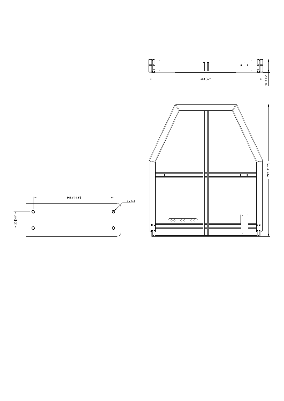
2.1.2. Dimensional drawing
Z5380 V Flying frame laser/inclinometer mounting plate [8]
dimensions in mm [inch]
Z5380 V Flying frame dimensions in mm [inch]
d&b V-Series Rigging manual (1.9 EN) 9
Page 10
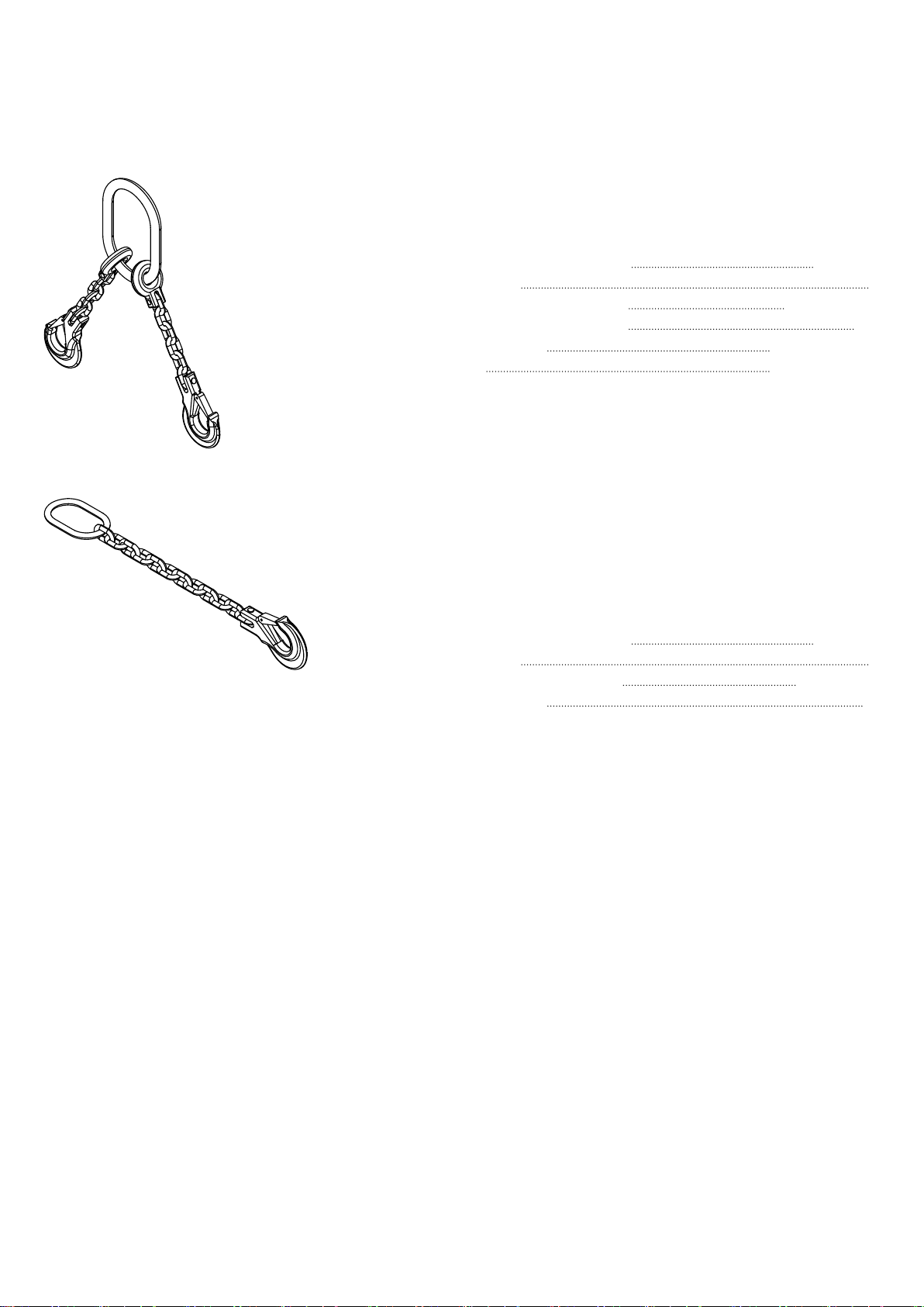
2.2. Z5382 V Safety chainset
The Z5382 V Safety chainset is supplied with the V Flying frame
and is used as a secondary safety device. Please also refer to
Þ Chapter 2.8. "Secondary safety" on page 16.
Specification
Lifting chain (DIN EN 818) 2-leg, 8 mm
Grade 8
Nominal length incl. hooks 416 mm (16.4")
Maximum sling angle b
Load rating 3.35 t (b: 0° - 45°)
Max
2.5 t (b: 46° - 60°)
60°
2.3. Z5381 V Hoist connector chain option
The Z5381 V Hoist connector chain is used to connect the lifting
motor(s) to the V Flying frame using the 2 t shackle which is
attached to the V Load adapter. Its length of 53 cm (21") allows
enough space for the hang of most 2 t motor chain containers and
avoids any impact on the vertical balance of the array when
suspended from a single pickpoint.
Specification
Lifting chain (DIN EN 818)
Grade 8
Nominal length incl. hook 535 mm (21")
Load rating 2 t
1-leg, 8 mm
d&b V-Series Rigging manual (1.9 EN)10
Page 11
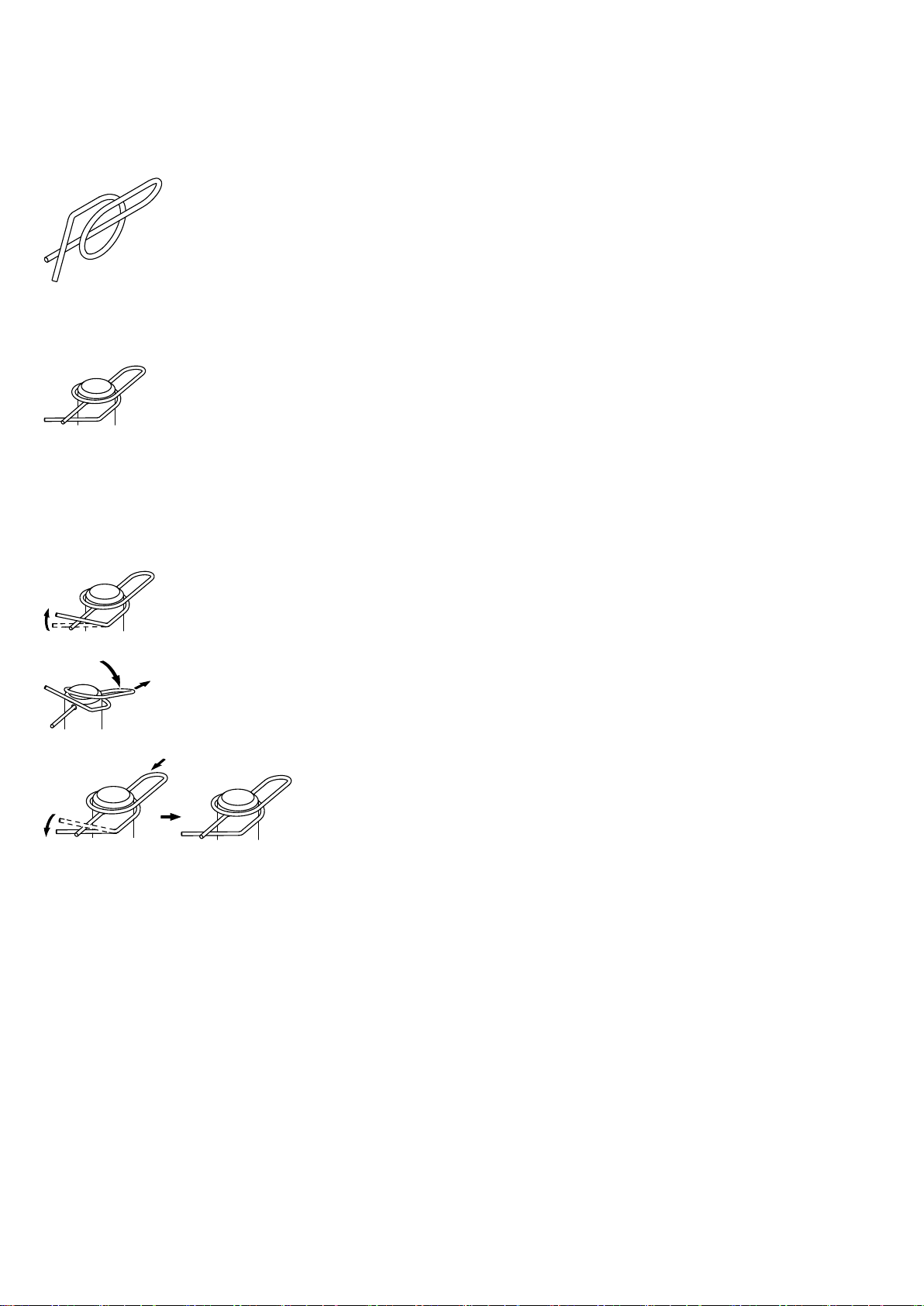
Ring cotter
Ring cotter locked
2.4. Ring cotters
In connection with the V-Series rigging system, ring cotters are used
for the following items to prevent the respective item from
slackening and/or loosening:
– Fixing bolt of the SUB cabinet's Rear link.
– Fixing bolt of the frame's Splay link and cable pick.
– Fixing bolt of the 2 t shackles attached to the Load adapters
and safety points of the Flying frame.
– Fixing bolt of the Z5147 Rota clamp.
Function of the ring cotter
By default, the ring cotters are "locked" to prevent them from
loosening.
For modification reasons such as altering the position of the frame's
Splay link or exchanging a shackle, it may be necessary to
temporarily remove the cotter and reattach it afterwards.
Note: Please also refer to Þ Chapter 7. " Care and
maintenance / Disposal", Þ section 7.2. " Visual and
functional inspection", Þ "Ring cotters" on page 43.
For this purpose proceed as follows:
1. Unlock
Unlock the ring cotter by pushing up the front wire loop over
the straight wire shaft.
2. Release and remove
Push down the rear wire loop until the ring cotter snaps over
the edge of the bolt and remove the ring cotter.
3. Refit and lock
Refit the ring cotter by pushing the straight wire shaft through
the hole and pressing the front wire loop underneath the
straight wire shaft.
d&b V-Series Rigging manual (1.9 EN) 11
Page 12
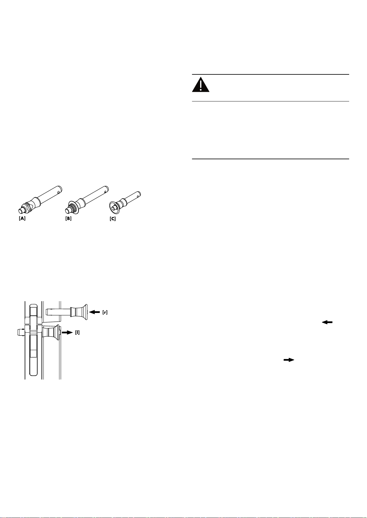
2.5. Locking pins
WARNING!
Potential risk of personal injury and/or
damage to material!
The steel wires between the Locking pins of the cabinets and
rigging components are not intended to carry any load. The
cabinet's weight must only be carried by the Front and Splay/Rear
links in conjunction with the front and rear rigging strands of the
loudspeaker cabinets and the Flying frame.
Ensure all Locking pins are fully inserted and securely locked
before lifting any load.
The V-Series loudspeaker cabinets and flying frame are equipped
with three types of Locking pins:
Locking pin assembly
Shown with pin type [C]
Type [A]
Locking pin 10 x 35 mm.
Used for the Load adapters.
Type [B] Locking pin 9 x 40 mm.
Used for the cabinets' Splay/Rear links and for the
frame's Splay link and Cable pick.
Type [C] Locking pin 8 x 23 mm.
Used for the Front links of the loudspeaker cabinets
and the frame.
Note: The Locking pins are undetachably attached to the
different rigging components on the cabinet and the frame
using steel wires.
Throughout this manual these steel wires are not shown in the
corresponding illustrations.
Functionality (Quick lock mechanism)
The quick lock mechanism applies to all types of Locking pins listed
above. Proceed as follows:
1. Press the button to release the locking mechanism ( [r]).
2. Remove the Locking pin through the respective link or socket.
3. Insert the Locking pin through the respective link or socket until
it is fixed in place.
4. Release the button to lock the pin ( [l]).
5. Recheck the Locking pin is securely locked by briefly pulling
the Locking pin towards you.
d&b V-Series Rigging manual (1.9 EN)12
Page 13
V-Series Load adapter
Y-Series Load adapter
Type 1/Type 2
Type 1/Type 2
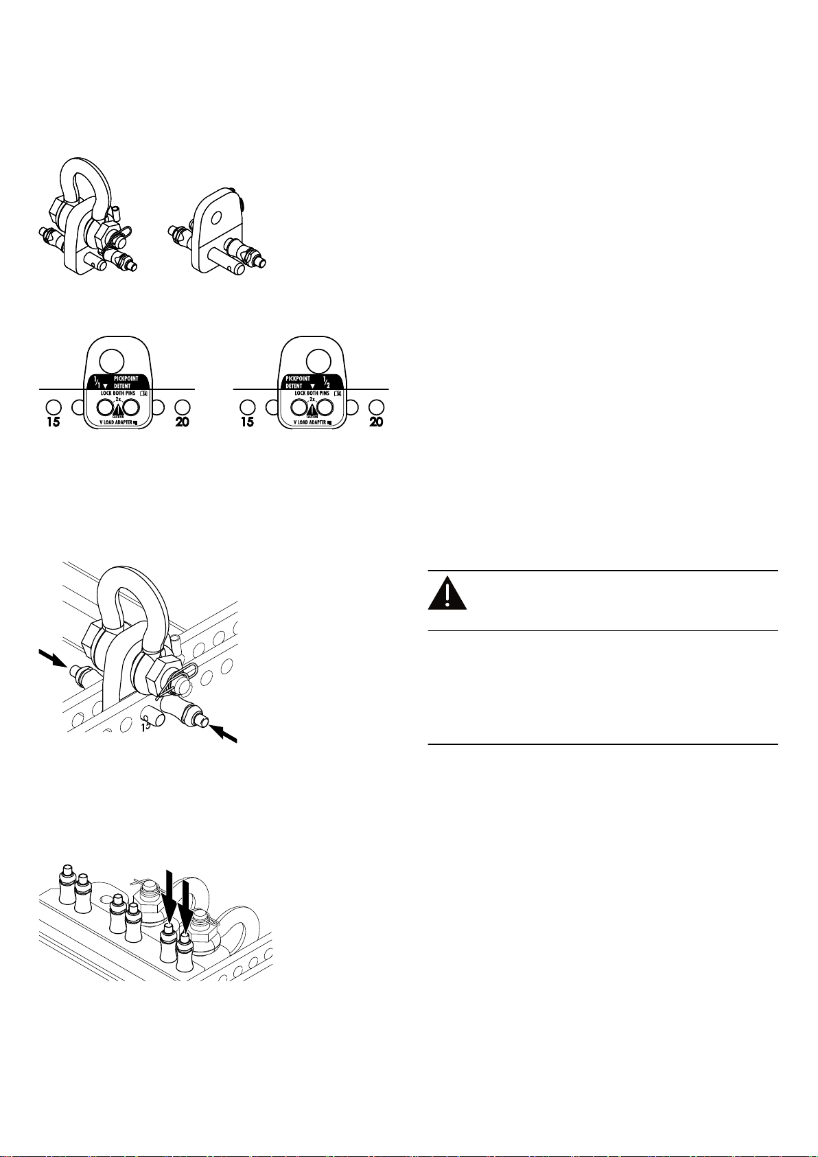
2.6. Load adapter
The Flying frame is supplied with two different types of load
adapters:
Type 1: 2 x V Load adapter, allowing either single or dual
pickpoint operation.
Type 2: 1 x V Load adapter Rota Clamp, allowing single
pickpoint operation in combination with the d&b
Z5147 Rota clamp for a maximum system weight of
up to 500 kg /1100 lb.
Both types allow for a full grid (1/1 PICKPOINT DETENT) or a half
grid (½ PICKPOINT DETENT) setting depending on the direction of
attachment to the frame's center bar.
The frame's hole index marked on one side of the center bar is the
reference for the direction of the Load adapter.
Direction of the Load adapter for:
Left: Full grid (1/1 PICKPOINT DETENT), shown: Hole 17
Right: Half grid (½ PICKPOINT DETENT), shown: Hole 17.5
As an example, the graphics opposite show hole positions 17 and
17.5 in connection with the V Load adapter.
As an example, the graphics opposite show hole positions 17 and
17.5 in connection with the Y Load adapter.
Note: The same applies to the V Load adapter Rota Clamp.
Attaching the Load adapter to the Flying frame
WARNING!
Potential risk of personal injury and/or
damage to material!
Before attaching the Load adapter, check the 2 t. shackle is
properly fitted to the Load adapter and secured with a locked ring
cotter.
Ensure the Load adapter is properly attached to the center bar of
the frame and both Locking pins are inserted and locked securely
before lifting the array.
The Load adapter is attached to the center bar of the Flying frame
and fixed using its two Locking pins 10 mm.
Note: It is advisable to insert the Locking pins opposite each
other as shown in the graphic opposite.
Fixing the Load adapter at Park position
During transport the Load adapters should be stored at their park
positions [P].
For this purpose, insert both Locking pins of each Load adapter in
the same direction from the top, as shown in the graphic opposite.
d&b V-Series Rigging manual (1.9 EN) 13
Page 14
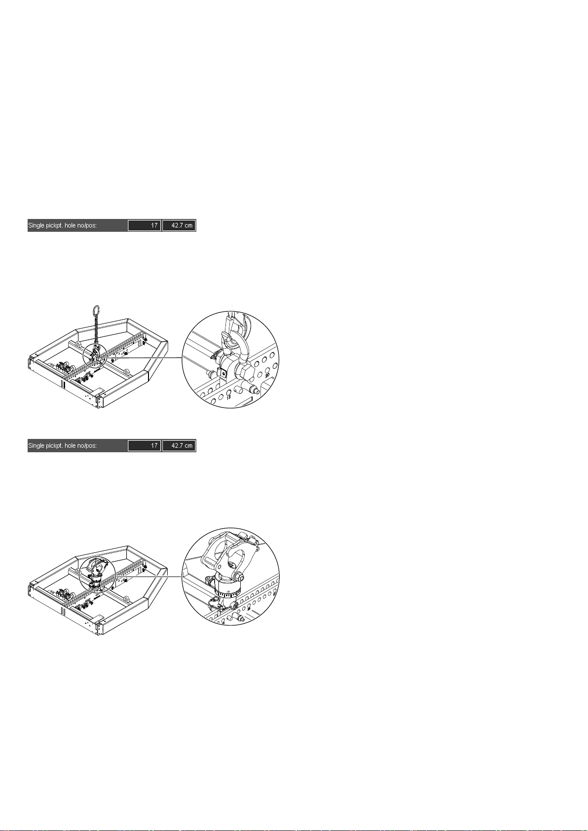
ArrayCalc Single pickpoint
2.7. Suspension of the Flying frame
The suspension of the V Flying frame is carried out using one or
two V Load adapter(s), depending on the chosen type of
suspension (Single or Dual pickpoint operation).
The Load adapters are attached to the center bar of the Flying
frame and fixed using the two Locking pins of each adapter as
described in the previous section Þ 2.6. Load adapter
Þ Attaching the Load adapter to the Flying frame on page 13.
2.7.1. Single pickpoint operation
With "Single pickpoint operation" the position of the V Load
adapter defines the vertical aiming of the entire array.
The corresponding hole position is calculated using ArrayCalc.
Note: The target angle of the entire array is achieved when
the array is fully set up and hoisted as intended.
Attachment
1. Choose the appropriate hole position on the center bar
according to the ArrayCalc calculation and attach the Load
adapter correspondingly.
If ArrayCalc displays a half numbered hole setting (half
Þ
grid) turn the Load adapter correspondingly.
2. Attach the Hoist connector chain or motor hook to the shackle
of the Load adapter.
ArrayCalc Single pickpoint
2.7.2. Z5147 Rota clamp option
Alternatively, a V-Series array with a total system weight of up to
500 kg (1100 lb) can be suspended and horizontally aligned
from a single flying point using the d&b Z5147 Rota clamp. The
clamp allows the load to be attached to overhead bars or truss
with a tube diameter of up to 51 mm (2”).
The corresponding hole position is calculated using ArrayCalc.
Attachment
1. Choose the appropriate hole position on the center bar
according to the ArrayCalc calculation and attach the Load
adapter Rota clamp correspondingly.
If ArrayCalc displays a half numbered hole setting (half
Þ
grid) turn the Load adapter correspondingly.
2. Attach the Rota clamp to the Load adapter.
Note: Please observe the relevant mounting instructions
which are enclosed with the Rota clamp.
d&b V-Series Rigging manual (1.9 EN)14
Page 15

ArrayCalc Dual pickpoint
2.7.3. Dual pickpoint operation
With "Dual pickpoint operation" the vertical aiming of the array is
set by trimming the hoist motors after the array has been fully
assembled and lifted to its operating position.
The corresponding hole positions are calculated using ArrayCalc.
Attachment
1. Choose the appropriate hole positions for the Front and
Rearpick on the Flying frame center bar according to the
ArrayCalc calculation and attach the Load adapters
correspondingly (Direction: Full grid 1/1 pickpoint Detent).
2. Connect the Hoist connector chains or motor hooks to the
shackles of the Load adapters.
d&b V-Series Rigging manual (1.9 EN) 15
Page 16

2.8. Secondary safety
WARNING!
Potential risk of personal injury and/or
damage to material!
The secondary safety suspension must be independent of the
primary suspension points and capable of carrying the total system
weight.
The additional safety device must be mounted in a way that the
array is caught by the safety device without any drop and swing in
the event that the primary suspension fails.
The Z5380 V Flying frame is equipped with two safety points [4]
fitted with two 2 t shackles to accept a secondary safety device.
We recommend the use of the d&b Z5382 V Safety chainset
which is supplied with the Flying frame.
Assembly
The two legs of the V Safety chainset and the distance [d]
between the two safety points [4] of the frame's tie bar form an
equilateral triangle maintaining the maximum sling angle (b
Max
) of
60°.
1. Before attaching the safety device ensure the two 2 t shackles
[S] are properly fitted to the frame's safety points [4] and
secured against loosening using a locked ring cotter [C] as
shown in the graphic opposite.
2. Attach the Safety chain and ensure the chains are not twisted
and the hooks [H] are in the right direction as shown in the
graphic opposite.
d&b V-Series Rigging manual (1.9 EN)16
Page 17

2.9. Splay link of the frame
Splay link position
By factory default the Splay link is attached and parked to
«POSITION V8/V12».
Depending on the type of cabinet (V8/V12 or V-SUB) to be
attached to the Flying frame the position of the frame's Splay link
needs to be changed as described in the following section
Þ Changing the Splay link position.
Splay link of the frame – «POSITION V8/V12»
Splay link at park position – «POSITION V8/V12»
Splay link of the frame – «POSITION V-SUB»
Splay link park position
During transport the Splay link can be folded into its park position
and fixed using its Locking pin.
Splay link at park position – «POSITION V-SUB»
Changing the Splay link position
WARNING!
Potential risk of personal injury and/or
damage to material!
The fixing bolt [B] of the frame's Splay link bears the full load of
the array.
It is essential that the bolt is fitted correctly and secured by a
locked ring cotter [C].
To change the Splay link position, proceed as follows:
d&b V-Series Rigging manual (1.9 EN) 17
Page 18

1. Release and remove the Locking pin of the Splay link at park
position and fold out the Splay link.
2. Unlock and remove the ring cotter of the fixing bolt.
3. Pull out the fixing bolt and remove the Splay link.
4. Attach the Splay link to its new position and insert the fixing
bolt.
5. Secure the fixing bolt using the ring cotter and ensure the ring
cotter is properly locked.
2.10. Cable pick
The Flying frame is equipped with an O-ring to allow the
attachment of a cable pick. To prepare the attachment of the cable
pick, proceed as follows:
1. Release the Locking pin holding the O-ring at park position.
2. Pull out the O-ring and reinsert the Locking pin.
Cable pick
d&b V-Series Rigging manual (1.9 EN)18
Page 19

2.11. Cabinet rigging mechanism
V-Series cabinets are mechanically connected to the V Flying frame
and subsequent loudspeakers using the Front links attached to both
sides of the cabinet front and the central Splay/Rear link at the
rear of the cabinet.
All necessary rigging components are mounted to the cabinet and
slide out when needed.
In principle, the Front link mechanism applies to both the V8/V12
and V-SUB cabinets.
2.11.1. Front link mechanism
V8/V12
1. Release both Locking pins and slide out the Front link.
2. Insert and lock one Locking pin to the upper hole to fix the link
in place.
V8/V12 Front link mechanism
V-SUB Front link mechanism
V-SUB
The Front link mechanism of the SUB cabinets provides four
different settings:
a. SUB to Frame (Þ Fig. 1)
b. SUB to SUB with 0° splay between the cabinets (Þ Fig. 2).
c. SUB to SUB with 2.5° splay (free Þ Fig. 3) between the
cabinets.
d. SUB to SUB with 2.5° splay (blocked Þ Fig. 4) between the
cabinets.
This setting is used to prevent the cabinets from folding up.
Fig. 1: SUB to Frame
d&b V-Series Rigging manual (1.9 EN) 19
Fig. 2: SUB to SUB, 0° splay
Fig. 3: SUB to SUB, 2.5° splay,
free
Fig. 4: SUB to SUB, 2.5° splay,
blocked
Page 20

Splay/Rear link mechanism
2.11.2. Splay/Rear link mechanism
Release the respective Locking pin(s) and fold out the Splay/Rear
link.
2.11.3. Preset splay angles on V8/V12 cabinets
The splay angles between adjacent cabinets can be set in the
range from 0° to 14° in 1° steps. The splay angles are set at the
central rear rigging strands of the cabinets.
– Insert and lock the Locking pin to the respective hole.
Preset splay angle (e.g. 7°)
Park position V8/V12 Splay link
2.11.4. Park position V8/V12 Splay link
The Splay link of the last cabinet of an array may be kept in its
park position.
Note: In this case, the lowest cabinet can be set to the
following splay angles: 3°, 5° and 7° to 14°.
d&b V-Series Rigging manual (1.9 EN)20
Page 21

3. V-Series arrays and assembly
V8 Line array 8-deep,
dual pickpoint operation,
shown with:
Z5381 V Hoist connector chain
Z5382 V Safety chainset
Refer to
V8/V12 Ground stack
Refer to
V-SUB column shown with 2.5°
splay between the cabinets
Refer to
Mixed array with
V-SUB at the top of the array
Refer to
V-SUB Ground stack
Refer to
Mixed ground stack
Refer to Þ Chapter 3.4.3. "Mixed
ground stack" on page 38
V Touring cart assembly
Refer to Þ Chapter 3.3. "V Touring cart
assembly" on page 30
d&b V-Series Rigging manual (1.9 EN) 21
Page 22

3.1. Setup preparation
Check the acoustical and mechanical setup using ArrayCalc and
prepare enough printouts for each array.
The plan enables the riggers to set up the suspension points, the
securing points and the chain hoists.
When on site first:
– Clear the working areas and ensure there is enough space to
set up and lift the array.
– Check that the hoists are exactly in the specified position.
– Ensure the chains are not twisted.
Inspections before setup
Before setup carry out a visual inspection of all system components
for faults. This also includes the loudspeakers and in particular the
rigging parts of the cabinets (Front and Splay/Rear links).
Damaged components must be withdrawn from use immediately.
Please follow the instructions given in Þ Chapter 7. "Care and
maintenance / Disposal" on page 43.
3.2. Flown arrays
Flown arrays are suspended using the Z5380 V Flying frame.
1. Suspend the Flying frame according to the chosen type of
suspension as described in Þ Chapter 2.7. "Suspension of the
Flying frame" on page 14.
2. At this point we recommend you to attach the secondary
safety device using the Z5382 V Safety chainset as described
in Þ Chapter 2.8. "Secondary safety" on page 16.
3. Prepare the cables and link cables according to the number of
amplifier channels and cabinets used.
d&b V-Series Rigging manual (1.9 EN)22
Page 23

Splay link of the frame – «POSITION V8/V12»
3.2.1. V8/V12 Array
Preparations
For this type of setup the Splay link of the frame must be attached
to «POSITION V8/V12». Check the position and alter it if
necessary as described in Þ Chapter 2.9. " Splay link of the
frame" Þ " Changing the Splay link position" on page 17.
1. Prepare the first cabinet
Prepare the Front and Splay links of the first cabinet as described
in Þ Chapter 2.11. " Cabinet rigging mechanism" on page 19.
2. Attach the Flying frame to the first cabinet
1. Lower the frame onto the cabinet until the Front links fit into the
slots at the front of the frame.
2. Insert and lock the second Locking pins of the cabinet's Front
links on both sides.
3. Release the Locking pin that keeps the frame's Splay link in its
park position.
4. Fold out the Splay link and reinsert the Locking pin.
5. On the rear rigging strand of the cabinet, insert and lock the
first Locking pin of the cabinet in the [0°] hole.
6. Slightly lower the frame and fold in the Splay link.
7. Lift the frame until the hook of the Splay link hooks into the
preset Locking pin.
8. Insert the second Locking pin (Safety pin) to secure the frame's
Splay link in place.
d&b V-Series Rigging manual (1.9 EN) 23
Page 24

3. Add further cabinets
1. Prepare the Front and Splay links of the next cabinet as
described in Þ Chapter 2.11. " Cabinet rigging mechanism"
on page 19.
2. Preselect the splay angle according to your ArrayCalc
simulation.
3. Lift the frame to a suitable working height.
4. Attach the prepared cabinet to the corresponding slots on the
front of the upper cabinet.
5. Insert and lock the second Locking pins of the cabinet's Front
links on both sides.
6. Raise the bottom cabinet until the Splay link of the upper
cabinet has hooked into the preset Locking pin.
7. Release the cabinet and insert the second Locking pin (Safety
pin) to secure the Splay link.
To add further cabinets proceed in the same manner until the
assembly is completed.
4. Rig the cabling
1. Connect the flying cables and link cables according to the
number of amplifier channels and cabinets used.
2. Attach the cable pick.
5. Check the assembly
Before hoisting the array to its operating position recheck the
actual status of the entire assembly according to the checklist given
in Þ Chapter 4. "Safety and system checks" on page 39.
d&b V-Series Rigging manual (1.9 EN)24
Page 25

Splay link of the frame – «POSITION V-SUB»
3.2.2. V-SUB Column
Preparations
For this type of setup the Splay link of the frame must be attached
to «POSITION V-SUB». Check the position and alter it if necessary
as described in Þ Chapter 2.9. " Splay link of the frame"
Þ " Changing the Splay link position" on page 17.
1. Prepare the first cabinet
Prepare the Front links of the first cabinet as described in section
Þ Chapter 2.11. " Cabinet rigging mechanism" on page 19.
2. Attach the Flying frame to the first cabinet
1. Lower the frame onto the cabinet until the Front links fit into the
slots at the front of the frame.
2. Insert the second Locking pins of the cabinet's Front links on
both sides.
3. On the rear rigging strand of the cabinet, release both Locking
pins.
4. Fold the Splay link into the rigging strand and reinsert the
Locking pins.
d&b V-Series Rigging manual (1.9 EN) 25
Page 26

3. Add further cabinets
1. Prepare the Front links of the next cabinet as described in
section Þ Chapter 2.11. " Cabinet rigging mechanism" on
page 19.
2. Lift the current assembly to a suitable working height.
3. Position the next cabinet below the assembly.
4. Lower the assembly onto the cabinet until the Front links of the
bottom cabinet fit into the slots of the upper cabinet.
5. Insert the second Locking pins of the cabinet's Front links on
both sides.
6. On the rear rigging strand, release the Locking pins of both
cabinets.
7. Fold out the Rear link of the upper cabinet.
8. Reinsert the Locking pin on the upper cabinet.
9. Fold the Rear link into the rigging strand of the bottom cabinet.
10. Reinsert the two Locking pins on the bottom cabinet.
SUB to SUB, 2.5° splay, free
To add further cabinets, proceed in the same manner until the
assembly is completed.
Splay option
The Front links of the SUB cabinets allow for a splay angle of 2.5°
between adjacent SUB cabinets. Before hoisting the array, the
angle can be set in two ways:
free
The second Locking pin of the cabinet's Front link is
inserted in the top hole of the front rigging strand as
shown in the graphic opposite. This can be done for
all cabinets in one step.
The angle opens itself as soon as the array is
hoisted.
blocked
The second Locking pin of each cabinet's Front link
is inserted in the second hole cabinet by cabinet
during hoisting as shown in the graphic opposite.
Due to the design of the Front link mechanism, the
Locking pin can be inserted free of load.
SUB to SUB, 2.5° splay, blocked
d&b V-Series Rigging manual (1.9 EN)26
Page 27

4. Rig the cabling
1. Connect the flying cables and link cables according to the
number of amplifier channels and cabinets used.
2. Attach the cable pick.
5. Check the assembly
Before hoisting the array to its operating position recheck the
actual status of the entire assembly according to the checklist given
in Þ Chapter 4. "Safety and system checks" on page 39.
d&b V-Series Rigging manual (1.9 EN) 27
Page 28

3.2.3. Mixed array
NOTICE!
If SUB cabinets are included in the array, these must always be
positioned at the top of the column.
Remarks
For a mixed setup two Flying frames are required. One frame is
used for suspension and the second frame acts as an adapter to
add V8/V12 cabinets below the SUB cabinets.
Since the first part of the setup is similar to the setup of a flown
SUB column as described in , this section only describes the
assembly of the second Flying frame below the SUB cabinets.
Preparations
For this type of setup the Splay link of the second frame must be
attached to «POSITION V8/V12». Check the position and alter it
if necessary as described in Þ Chapter 2.9. " Splay link of the
frame" Þ " Changing the Splay link position" on page 17.
Splay link of the frame – «POSITION V8/V12»
1. Prepare the second Flying frame
To attach the second frame below the SUB cabinets, the two
additional Front links of the frame are needed.
1. Remove the additional Front links together with their Locking
pins from their park positions on the frame.
2. Attach the additional Front links at the top of the front tracks of
the frame and fix them with one Locking pin each.
Note:
Observe the direction of attachment as shown in the
graphic opposite.
2. Attach the assembly to the frame
1. Lift the assembly to allow the second frame to be positioned
below the assembly.
2. Position the frame below the assembly.
3. Fold out the Rear link of the SUB cabinet.
d&b V-Series Rigging manual (1.9 EN)28
Page 29

4. Lower the assembly onto the frame until
the Front links fit into the slots at the front of the frame
and the Rear link fits into the track of the frame's center bar.
5. Insert the second Locking pins of the Front links on both sides.
6. On the rear rigging strand of the cabinet, insert the (first)
Locking pin of the cabinet's Rear link to the fixing hole of the
frame's center bar.
7. Release the Locking pin of the cable pick and insert it to the
second fixing hole of the frame's center bar.
3. Add V8/V12 cabinets below the SUBs
Adding V8/V12 cabinets below the SUBs is similar to the setup of
a flown V8/V12 array as described in .
4. Rig the cabling
1. Connect the flying cables and link cables according to the
number of amplifier channels and cabinets used.
2. Attach the cable pick.
5. Check the assembly
Before hoisting the array to its operating position recheck the
actual status of the entire assembly according to the checklist given
in Þ Chapter 4. "Safety and system checks" on page 39.
d&b V-Series Rigging manual (1.9 EN) 29
Page 30

3.3. V Touring cart assembly
The V Touring cart allows for a quick and easy setup of arrays as
the entire cabinet assembly stored in the cart can be directly
connected to the V Flying frame or mounted below already
suspended V8/V12 or V-SUB cabinets.
This type of setup is also very efficient when working space is
restricted.
3.3.1. Assembly
Remarks
For the assembly the same general preparations are made as
described in .
The setup should always be carried out by two persons.
The rigging procedure described below applies to both touring
cart options.
Splay link of the frame
For this type of setup, the Splay link of the frame must be attached
to «POSITION V8/V12». Check the position and alter it if
necessary as described in Þ Chapter 2.9. " Splay link of the
frame" Þ " Changing the Splay link position" on page 17.
Splay link of the frame – «POSITION V8/V12»
3.3.1.1. Cabinet assembly to Flying frame
1. Prepare the touring cart
1. Move the cart to its assembly position.
2. Unlock the four fasteners (CamLocks) on the top lid and take
off the lid.
3. Unlock the four fasteners (CamLocks) on the bottom tray and
remove the connecting poles.
d&b V-Series Rigging manual (1.9 EN)30
Page 31

2. Prepare the cabinets
1. On the rear first remove all Locking pins.
2. Preset the splay angles of all cabinets based on your
ArrayCalc simulation.
Note: If the cabinet assembly is connected directly to the
Flying frame, the splay angle of the first (top) cabinet must be
set to [0°].
3. On the top cabinet, release both Locking pins and slide out the
Front link.
4. Insert and lock one Locking pin to fix the link in place.
3. Attach the Flying frame
1. Lower the frame onto the first cabinet of the assembly until the
Front links fit into the slots at the front of the frame.
2. Insert and lock the second Locking pins of the cabinet's Front
links on both sides.
3. Release the Locking pin that keeps the frame's Splay link in its
park position.
4. Fold out the Splay link and reinsert the Locking pin.
d&b V-Series Rigging manual (1.9 EN) 31
Page 32

5. On the rear rigging strand of the first cabinet, check the splay
angle is set to [0°].
6. Slightly lower the frame and fold in the Splay link into the
strand.
7. Lift the frame until the Splay link hooks into the preset Locking
pin.
8. Insert and lock the second Locking pin (Safety pin) to secure
the Splay link in place.
4. Apply and fix the preset splay angles
The Splay links will be engaged automatically while lifting the
assembly.
1. Slowly lift the cabinet assembly out of the cart until all Splay
links have hooked into the preset Locking pins.
2. Stop lifting and insert and lock the second Locking pins (Safety
pins) to secure the Splay links in place.
Note: In certain cases, the Splay links may not be engaged
automatically. In this case, the Splay angles of the cabinets
should be applied and fixed in the cart before the assembly is
connected to the array. For this purpose, proceed as follows:
4a. Apply and fix the preset splay angles manually
1. Raise the back of the cabinet until the Splay link has hooked
into the preset Locking pin of the bottom cabinet.
2. Hold the cabinet in place and insert the second Locking pin
(Safety pin) to fix the Splay link.
To apply and fix the splay angles of further cabinets, proceed in
the same manner.
d&b V-Series Rigging manual (1.9 EN)32
Page 33

3.3.1.2. Cabinet assembly below V8/V12 cabinets
Preparations
To mount the cabinet assembly below already suspended V8/V12
cabinets, prepare the respective cabinet assembly in the same
manner as described in the previous section Þ 3.3.1.1. " Cabinet
assembly to Flying frame", Þ "2. Prepare the cabinets"
on page 30.
1. Attach the assembly to the array
1. Lower the array until the Front links of the top cabinet in the
cart fit into the slots at the front of the bottom cabinet in the
array while a second person secures the cart against moving
and tipping over.
2. Insert and lock the second Locking pins of the cabinet's Front
links on both sides.
2. Apply and fix the preset splay angles
1. Slowly lift the cabinet assembly out of the cart until all Splay
links have hooked into the preset Locking pins.
2. Stop lifting and insert and lock the second Locking pins (Safety
pins) to secure the Splay links in place.
Note:
If the Splay links are not engaged automatically,
proceed in the same manner as described in the pervious
section Þ 3.3.1.1. " Cabinet assembly to Flying frame"
Þ " 4a. Apply and fix the preset splay angles manually" on
page 32.
3. Connect the bottom assembly to the Splay link of
the upper assembly
1. With two persons raise the entire assembly until the Splay link
of the array's bottom cabinet hooks into the preset Locking pin.
2. Slightly lower the assembly to allow the second Locking pin
(Safety pin) to be inserted.
3. Insert and lock the second Locking pin (Safety pin) to secure
the Splay link in place.
4. Rig the cabling
Connect the flying cables and link cables according to the number
of amplifier channels and cabinets used.
5. Check the assembly
Before hoisting the array to its operating position recheck the
actual status of the entire assembly according to the checklist given
in Þ Chapter 4. "Safety and system checks" on page 39.
d&b V-Series Rigging manual (1.9 EN) 33
Page 34

3.3.1.3. Cabinet assembly below V-SUB cabinets
Mounting the cabinet assembly below already suspended V-SUB
cabinets is similar to the procedure described in the previous
section Þ Chapter 3.3.1.2. "Cabinet assembly below V8/V12
cabinets" on page 33.
However, due to the possible size and weight of the suspended
SUB assembly, carry out the assembly very carefully and
considerably.
We recommend you to apply and fix the splay angles of the TOP
cabinets in the cart manually, before attaching the SUB assembly.
For this purpose proceed as follwos:
Apply and fix the preset splay angles manually
1. Raise the back of the cabinet until the Splay link has hooked
into the preset Locking pin of the bottom cabinet.
2. Hold the cabinet in place and insert the second Locking pin
(Safety pin) to fix the Splay link.
To apply and fix the splay angles of further cabinets, proceed in
the same manner.
3.3.1.4. Cart storage
The most space-saving way to store the carts during an event is to
place the connecting poles into the bottom tray and attach the top
lid to the bottom tray.
The conical connectors of the bottom tray will keep the top lid fixed
in place.
d&b V-Series Rigging manual (1.9 EN)34
Page 35

Splay link removed and Cable pick attached to hole 35.
3.4. Ground stacks
WARNING!
Potential risk of personal injury and/or
damage to material!
Always secure ground stacked setups against movement and
possible tipping over.
Observe the maximum number of cabinets permitted. This is
particularly important when setting up mixed ground stacks.
3.4.1. V8/V12 ground stack
Limitations
A maximum of 8 x TOP cabinets with the V Flying frame serving as
ground support are allowed to be set up as ground stack.
Preparations
In this type of setup the V Flying frame is used as ground support.
For this purpose, the Splay link of the frame must be removed and
stored in a safe place.
The Locking pin of the Cable pick will be used to fix the vertical
aiming of the first TOP cabinet on the Flying frame at a later stage.
For this reason, the Cable pick assembly (O-ring) must be attached
to hole 35 of the Frame's hole grid.
Proceed as follows:
1. Prepare the Flying frame
To attach the TOP cabinets to the Flying frame, the two additional
Front links of the frame are required.
1. Remove the additional Front links together with their Locking
pins from the park position on the frame.
2. Attach the additional Front links at the top of the front tracks of
the frame and fix them using one Locking pin.
Þ Observe the direction of attachment as shown in the
graphic opposite.
d&b V-Series Rigging manual (1.9 EN) 35
Page 36

2. Change the position of the Cable pick
1. Release and remove the Locking pin of the Cable pick.
2. Unlock and remove the ring cotter of the fixing bolt.
3. Pull out the fixing bolt and take off the O-ring.
4. Attach the O-ring to its new position (hole 35) and insert the
fixing bolt.
5. Reinsert the ring cotter to secure the fixing bolt and ensure the
ring cotter is properly locked.
3. Attach the first cabinet to the frame
1. Place the cabinet onto the frame until the additional Front links
fit into the slots at the front of the cabinet.
2. Insert the second Locking pins of the additional Front links on
both sides.
4. Set the vertical aiming of the first cabinet
The hole grid on the Flying frame allows the first cabinet to be set
to a fixed vertical angle of –7°, –3.5°, 0°, +3.5° or +7°. The
hole (drill) of the cabinet's Splay link is used for this purpose. It
supports the cabinet and defines the angle setting.
1. Release the Locking pins of the cabinet's Splay link.
2. Fold out and insert the Splay link into the track of the center
bar of the frame and align the hole of the link with the desired
hole of the frame.
3. Fix the angle of the cabinet using the Locking pin of the Cable
pick.
5. Add further cabinets
1. Release the Locking pins of the Front links of the first cabinet.
2. Slide out the Front links and insert one Locking pin each to fix
them in place.
3. Attach the next cabinet to the Front links and insert the second
Locking pins on both sides.
d&b V-Series Rigging manual (1.9 EN)36
Page 37

4. At the rear, release both Locking pins of the upper cabinet's
Splay link.
5. Preset the desired splay angle on the rear rigging strand of the
bottom cabinet using one Locking pin.
6. Fold the Splay link of the upper cabinet into the rigging strand
of the bottom cabinet.
7. Raise the upper cabinet until the hook of the Splay link hooks
into the preset Locking pin.
8. Hold the cabinet in place and insert the second Locking pin
(Safety pin) to fix the Splay link in place.
To add further cabinets, proceed in the same manner until the
assembly is completed.
6. Rig the cabling
Connect the flying cables and link cables according to the number
of amplifier channels and cabinets used.
7. Check the assembly
Recheck the actual status of the entire assembly according to the
checklist given in Þ Chapter 4. "Safety and system checks"
on page 39.
3.4.2. V-SUB stack
Limitations
A maximum of 8 x SUB cabinets are allowed to be set up as SUB
stack.
1. Assembly
Stack the SUB cabinets and interconnect them with their Front and
Rear links.
2. Rig the cabling
Connect the flying cables and link cables according to the number
of amplifier channels and cabinets used.
3. Check the assembly
Recheck the actual status of the entire assembly according to the
checklist given in Þ Chapter 4. "Safety and system checks"
on page 39.
d&b V-Series Rigging manual (1.9 EN) 37
Page 38

3.4.3. Mixed ground stack
Limitations
A combination of 8 x TOP/SUB cabinets at maximum are allowed
to be set up as mixed ground stack.
Preparations
For this type of setup the Splay link of the frame must be attached
to «POSITION V-SUB». Check the position and alter it if necessary
as described in Þ Chapter 2.9. " Splay link of the frame"
Þ " Changing the Splay link position" on page 17.
Splay link of the frame –
«POSITION V-SUB»
1. Assembly
1. Stack the SUB cabinets and interconnect them using their Front
and Rear links.
2. Prepare the Front links of the upper SUB cabinet as described
in Þ Chapter 2.11.1. "Front link mechanism" on page 19.
3. Place the frame onto the cabinet until the Front links fit into the
slots at the front of the frame.
4. Insert the second Locking pins of the cabinet's Front links on
both sides.
5. On the rear rigging strand of the cabinet, release both Locking
pins.
6. Fold the frame's Splay link into the rigging strand and reinsert
the Locking pins.
The assembly of the V8/V12 cabinets on top of the frame is
carried out in the same manner as described in the previous
section Þ Chapter 3.4.1. "V8/V12 ground stack" on page 35.
2. Rig the cabling
Connect the flying cables and link cables according to the number
of amplifier channels and cabinets used.
3. Check the assembly
Recheck the actual status of the entire assembly according to the
checklist given in Þ Chapter 4. "Safety and system checks"
on page 39.
d&b V-Series Rigging manual (1.9 EN)38
Page 39

4. Safety and system checks
Before hoisting the array to its operating position recheck the
actual status of the assembly as follows:
Note: When applicable, the same system and safety checks
also apply to ground stack assemblies.
4.1. Mechanical setup
– Check the attachment of the Load adapter(s) to the Flying
frame and ensure all Locking pins are properly inserted and
locked.
– Check the attachment of the secondary safety device at the
Flying frame (refer to section Þ Chapter 2.8. "Secondary
safety" on page 16).
– Check the attachment of the Flying frame(s) to the cabinets
and ensure all Locking pins are properly inserted and locked.
– Check the attachment of all Front links on both sides of the
cabinets and ensure all Locking pins are properly inserted and
locked.
– Check the splay angles and the attachment of the Splay/Rear
links on the rear of the cabinets and ensure all Locking pins
are properly inserted and locked.
– In "Single pickpoint operation" check the desired total vertical
aiming of the entire array using an inclinometer.
4.2. Wiring
– Check the wiring.
If the amplifiers are already wired and powered on, use their
System check functions or Channel mute switches and a test
signal to check the correct operation and routing of all
channels and cabinets.
d&b V-Series Rigging manual (1.9 EN) 39
Page 40

5. Hoisting and securing the array
5.1. Hoisting the array
WARNING!
Potential risk of personal injury and/or
damage to material!
Always ensure that each of the hoists is able to carry the total
weight of the array.
When hoisting the array, unpredictable dynamic forces as well as
swinging of the array must be taken into account. This may lead to
personal injury and/or damage to the rigging components and
loudspeaker cabinets.
Ensure that there is nobody directly underneath or in the vicinity of
the load who is not involved in the setup.
When all the mechanical adjustments, system checks and safety
checks have been made, the array can be hoisted up to its
operating position.
When hoisting the array, ensure that the loudspeaker cables do
not get caught anywhere. The cables can be strapped together
with the motor cable to form a loom while the system is hoisted.
The chain hoist motors must raise the system slowly and evenly so
that it does not swing or move from side to side during hoisting.
5.2. Securing the array
When the array is in its final operating position the secondary
safety must be applied. A detailed description is given in
Þ Chapter 2.8. "Secondary safety" on page 16.
d&b V-Series Rigging manual (1.9 EN)40
Page 41

6. Derigging
6.1. General
To dismantle any of the assemblies described above, follow the
corresponding assembly instructions in reverse order.
The same safety instructions apply.
6.2. Touring cart disassembly
With respect to the touring carts the following procedure is strongly
recommended.
CAUTION!
Potential risk of personal injury and/or
damage to material!
In particular make sure that when lowering the array nobody is
directly underneath or in the vicinity of the array.
When lowering the array onto the cart avoid diagonal pull.
This could lead to the potential risk of the array tipping over
towards the front.
Depending on the type of surface (arena floor/outdoor field) the
cart could suddenly slide out of position and could cause a
potentially dangerous situation which may lead to personal injury.
1. Dismantle the first cabinet assembly
1. Lower the array to a suitable working height.
2. Release the Safety pin of the Splay link on the lowest cabinet
of the upper assembly.
3. With two persons raise the bottom assembly and fold out the
Splay link of the upper assembly.
4. Carefully lower the bottom assembly.
5. Release all Safety pins of the bottom assembly.
Note: To prevent the Safety pins from getting jammed while
the assembly is lowered onto the cart, reinsert the Safety pins
in one of the remaining holes in the rear rigging strands of the
cabinets.
d&b V-Series Rigging manual (1.9 EN) 41
Page 42

6. Lower the array slowly and evenly onto the cart until the Front
links are load-free.
7. Release the Locking pins of the Front links on the top cabinet of
the assembly while a second person renders support to
prevent the upper suspended assembly from unpredictable
swing.
8. Slowly lift the remaining assembly to allow the cart to be
turned or moved aside.
Proceed in the same manner until the array is completely
dismantled.
2. Reassembling the cart
1. Slide in the Front links of the top cabinet and reinsert the two
Locking pins.
2. Attach the connecting poles to the bottom tray and lock all
fasteners (CamLocks).
3. Attach the top lid and lock all fasteners (CamLocks).
Note: The top lids of the touring carts are equipped with
additional guiding tracks to fix the cabinet assemblies in place.
In conjunction with the E7463 V Touring cart 4 x V8/V12
observe the direction of attachment as shown in the graphic
below.
d&b V-Series Rigging manual (1.9 EN)42
Page 43

7. Care and maintenance / Disposal
7.1. Transport / Storing
During transport ensure the rigging components are not stressed or
damaged by mechanical forces. Use suitable transport cases.
We recommend the use of the d&b E7463 or E7464 V Touring
cart for this purpose.
Due to their surface treatment the rigging components are
temporarily protected against moisture. However, ensure the
components are in a dry state while stored or during transport and
use.
7.2. Visual and functional inspection
WARNING!
Potential risk of personal injury and/or
damage to material
To eliminate the potential risk of accident due to malfunctioning of
a component, regularly inspect all system components.
Cabinet enclosure
– Visual inspection of all fitting plates for obvious damage (e.g.
cracks or corrosion).
– Visual inspection of the rear rigging strand for obvious
damage (e.g. cracks, deformation or corrosion) including all
drilled holes of the component.
– Inspection of all fitting plates including front grills to ensure
they are securely attached.
– Regularly lubricate the sockets using WD-40® or a similar
product.
Front and Splay (Rear) links
Visual inspection regarding deformation and damage (e.g. cracks
and corrosion) including all drilled holes of the component.
Locking pins
– Visual inspection for deformation, cracks and corrosion of the
component.
– Inspection for missing ball bearings and damage.
– Functional inspection of the release mechanism to ensure it
operates properly.
– Regularly lubricate the Locking pins using WD-40® or a similar
product.
d&b V-Series Rigging manual (1.9 EN) 43
Page 44

Condition of the ring cotter
[a]: Ring cotter OK
[b]: Exchange the ring cotter
Ring cotters
– Visual inspection for obvious damage and deformation.
– Functional test of the locking mechanism as described in
Þ Chapter 2.4. "Ring cotters" on page 11.
If a ring cotter can no longer be properly fitted to the fixing
bolt and locked, it must be exchanged.
Z5380 V Flying frame
– Visual inspection regarding deformation and damage (e.g.
cracks and corrosion) including all drilled holes of the
component.
– Regularly check the flatness of the Flying frame. For this
purpose position the Flying frame on a flat surface and visually
check the frame for deformation and/or torsion. For obvious
deformation and/or torsion contact d&b audiotechnik for
further advice on how to proceed.
Z5381 V Hoist connector chain / Z5382 V Safety chain
Inspection according to the appropriate regulations for lifting
devices (EN 818-6:2000). Regularly inspect within a 12 months
period. Regularly inspect for cracks within a 36 months period.
7.3. Disposal
When out of use the rigging components must be disposed of in
accordance with the national environmental regulations.
Ensure that damaged rigging components are disposed of in a
way that they cannot be used again.
d&b V-Series Rigging manual (1.9 EN)44
Page 45

8. Manufacturer's declaration
We hereby declare that the equipment designated below is
designed and built in the version sold by us in such a way as to
comply with the relevant fundamental safety and health criteria of
the applicable EC Directive(s). This declaration shall cease to be
valid if alterations are made to the equipment without our prior
agreement.
This declaration covers:
d&b V-Series loudspeaker cabinets
(With integrated rigging components.)
– Z0515 V8
– Z0516 V12
– Z0518 V-SUB
d&b V-Series rigging components
(Including all additional components such as Load adapter, Front
links frame, shackles.)
– Z5380 V Flying frame
– Z5381 V Hoist connector chain
– Z5382 V Safety chainset
National standards and technical specifications
applied:
DIN EN ISO 12 100, DIN EN 1050, BGV C1.
Backnang, -2014-08
Frank Bothe,
Head of R&D
d&b audiotechnik GmbH
d&b V-Series Rigging manual (1.9 EN) 45
Page 46

D2702.EN .01, 11/2014 © d&b audiotechnik GmbH
www.dbaudio.com
 Loading...