

Page 1
MANUALE D’USO – Sezione 1
USER MANUAL - Section 1
BEDIENUNGSANLEITUNG - Abschnitt 1
CARACTERISTIQUES TECHNIQUES - Section 1
MANUAL DEL USUARIO - Sección 1
Le avvertenze nel presente manuale devono essere osservate congiuntamente al “MANUALE D’USO - Sezione2”.
The warnings in this manual must be observed together with the “USER MANNUAL- Section 2”.
Die Warnungen in diesem Handbuch müssen in Verbindung mit der “BEDIENUNGSANLEITUNG - Abschnitt 2” beobachtet werden”.
Les avertissements speciés dans ce manuel doivent être respectés ainsi que les “CARACTERISTIQUES TECHNIQUES -Section 2”.
Las advertencias del presente manual se deben tener en cuenta conjuntamente con las del “Manual del usuario” - Sección 2”.
Page 2

EMI CLASSIFICATION
EMI CLASSIFICATION
According to the standards EN 55103 this equipment is designed and suitable to operate in E5 Electromagnetic
environments.
FCC CLASS A STATEMENT ACCORDING TO TITLE 47, PART 15, SUBPART B,
§15.105
This equipment has been tested and found to comply with the limits for a Class A digital device, pursuant to part
15 of the FCC Rules.
These limits are designed to provide reasonable protection against harmful interference when the equipment is
operated in a commercial environment.
This equipment generates, uses and can radiate radio frequency energy and, if not installed and used in
accordance with the instructions, may cause harmful interference to radio communications.
Operation of this equipment in a residential area is likely to cause harmful interference in which case the user will
be required to correct the interference at his own expense.
Changes or modications not expressly approved by the party responsible for compliance could void the user’s
authority to operate the equipment.
WARNING
Make sure that the loudspeaker is securely installed in a stable position to avoid any injuries or damages to
persons or properties. For safety reasons di not place one loudspeaker on top of another without proper fastening
systems. Before hanging the loudspeaker check all the components for damages, deformations, missing or
damaged parts that may compromise safety during installation. If you use the loudspeakers outdoor avoid spots
exposed to bad weather conditions.
Contact dBTechnologies for accessories to be used with the speakers. dBTechnologies will not accept any
responsibility for damages caused by inappropiate accessories or additional devices.
VIO-S118
2
Cod. 420120259 REV. 1.0
Page 3
IMPORTANT SAFETY INSTRUCIONS:
1. Read these instructions
2. Keep these instructions.
3. Heed all warnings.
4. Follow all instructions.
5. Do not use this apparatus near water.
6. Clean only with dry cloth.
7. Do not block any ventilation openings. Install in accordance with the manufacturer’s instructions.
8. Do not install near any heat sources such as radiators, heat registers, stoves, or other apparatus (including
ampliers) that produce heat.
9. Do not defeat the safety purpose of the polarized or grounding-type plug. A polarazied plug has two blades
with one wider than the other. A grounding type plug has two blades and a third grounding prong. The wide
blade or the third prong are provided for your safety. If the provided plug does not t into your outlet, consult
an electrician for replacement of the obsolete outlet.
10. Protect the power cord from being walked on or pinched particularly at plugs, convenience receptacles, and
the point where they exit from the apparatus.
11. Only use attachements/accessories specied by the manufacturer.
12. Use only with the cart, stand tripod, bracket, or table specied by the manufacturer, or sold with
the apparatus. When a cart is used, use caution, when moving the cart/apparatus combination to
avoid injury from tip-over.
13. Unplug this apparatus during lightning storms or when unused for long periods of time.
14. Refer all servicing to qualied service personnel. Servicing is required when the apparatus has benn damaged
in any way, such as power-supply cord or plug is damaged, liquid has benn spilled or objects have fallen into
the apparatusm the apparatus has been exposed to rain or moisture, does not operate normally, or has been
dropped.
ADDITIONAL SAFETY INSTRUCTIONS:
• No naked ame sources, such as lighted candles, should be placed on the apparatus
• Do not use the apparatus in tropical climates
VIO-S118 Cod. 420120259 REV. 1.0
3
Page 4
CONSIGNES DE SÉCURITÉ IMPORTANTES :
1. Lire ces instructions
2. Conserver ces instructions.
3. Faire attention à tous les avertissements.
4. Respecter toutes les consignes.
5. Ne pas utiliser l’appareil à proximité d’un point d’eau.
6. Nettoyer uniquement à l’aide d’un chiffon sec.
7. Ne pas bloquer les conduits d’aération. Installer conformément aux instructions du fabricant.
8. Ne pas installer à proximité de sources de chaleur telles que les radiateurs, les grilles de chauffage, les
cuisinières, ou d’autres appareils (dont les amplicateurs) produisant de la chaleur.
9. Ne pas compromettre la sécurité de la che polarisée ou de terre. La che polarisée comprend deux lames
dont l’une est plus large que l’autre. La che de terre comprend deux lames et une broche de mise à la terre.
La lame la plus large ou la broche sont fournies pour des raisons de sécurité. Lorsque la che fournie ne
correspond pas à la prise, se référer à un électricien an de remplacer la prise obsolète.
10. Protéger le câble d’alimentation an qu’il ne soit pas écrasé ou coincé, en particulier au niveau des ches, des
prises de courant et du point de sortie de l’appareil.
11. Utiliser uniquement les instruments/accessoires spéciés par le fabricant.
12. Utiliser uniquement avec le chariot, le trépied, l’étrier ou la table spéciés par le fabricant, ou
vendus avec l’appareil. Dans le cas d’un chariot, faire attention lors de tout déplacement de l’unité
chariot/appareil an d’éviter toute blessure en cas de renversement.
13. Débrancher l’appareil en cas d’orages ou d’inutilisation prolongée.
14. Coner toute opération d’entretien au personnel qualié. L’entretien est nécessaire lorsque l’appareil a été
endommagé, par exemple lorsque le câble d’alimentation ou la che sont endommagés, du liquide a été
renversé ou des objets sont tombés dans l’appareil, l’appareil a été exposé à la pluie ou à l’humidité, il ne
marche pas normalement ou il est tombé.
CONSIGNES DE SÉCURITÉ SUPPLÉMENTAIRES :
• Ne pas placer de sources de amme nue, telles que des bougies allumées, sur l’appareil
• Ne pas utiliser l’appareil dans des climats tropicaux
VIO-S118
Cod. 420120259 REV. 1.0
4
Page 5

ITALIANO
ENGLISH
DEUTSCH
FRANÇAIS
ESPAÑOL
VIO-S118 Cod. 420120259 REV. 1.0
5
Page 6

Italiano
INDICEINDICE
1. INFORMAZIONI GENERALI ................................................................................................... 7
BENVENUTI! ........................................................................................................................ 7
PANORAMICA INTRODUTTIVA .......................................................................................... 7
RIFERIMENTI PER L’UTENTE ................................................................................................ 7
CARATTERISTICHE MECCANICHE ED ACUSTICHE ............................................................. 8
DIMENSIONI E PESO .................................................................................................................................. 8
MECCANICA ............................................................................................................................................... 9
ACCESSORI ............................................................................................................................................... 11
CARATTERISTICHE DELLA SEZIONE DI AMPLIFICAZIONE E DI CONTROLLO ................. 13
SEZIONE DI INPUT, OUTPUT E DI CONTROLLO ...................................................................................... 14
SEZIONE DI ALIMENTAZIONE .................................................................................................................. 16
2. DBTECHNOLOGIES COMPOSER (rev. 6.3.0 o successiva) ................................................ 17
3. COLLEGAMENTI ................................................................................................................... 21
COLLEGAMENTO E RILANCIO DELL’ALIMENTAZIONE............................................................................. 21
COLLEGAMENTO E RILANCIO DEL SEGNALE AUDIO E RDNET .............................................................. 22
4. CONFIGURAZIONI E CONTROLLO REMOTO ..................................................................... 23
CONFIGURAZIONI CARDIOIDE ED ENDFIRE ................................................................... 23
5. INSTALLAZIONE E CONFIGURAZIONE ............................................................................... 25
INSTALLAZIONE FLOWN (ESEMPIO DI 1 ARRAY CON 3 VIO-S118 IN ............................ 25
CONFIGURAZIONE CARDIOIDE E 8 VIO-L210) ................................................................ 25
INSTALLAZIONE STACKED (ESEMPIO DI 1 MODULO VIO-L210 su VIO-S118) ................ 29
6. RISOLUZIONE DEI PROBLEMI ............................................................................................. 30
7. AGGIORNAMENTO DEL FIRMWARE .................................................................................. 31
8. SPECIFICHE TECNICHE ......................................................................................................... 32
GENERALE ................................................................................................................................................ 32
DATI ACUSTICI .......................................................................................................................................... 32
AMPLIFICATORE ....................................................................................................................................... 32
PROCESSORE ............................................................................................................................................ 32
INTERFACCIA UTENTE .............................................................................................................................. 33
INGRESSI ED USCITE ................................................................................................................................ 33
SPECIFICHE DI ALIMENTAZIONE (ASSORBIMENTO) ............................................................................... 33
SPECIFICHE MECCANICHE ....................................................................................................................... 34
VIO-S118
6
Cod. 420120259 REV. 1.0
Page 7
Italiano
1. INFORMAZIONI GENERALI
BENVENUTI!
Grazie per aver acquistato un prodotto progettato e sviluppato in Italia da dBTechnologies! Questo subwoofer
attivo, potente e dal montaggio agevole, è frutto di una lunga esperienza nel campo della diffusione sonora.
Impiega soluzioni ottimizzate in campo acustico ed elettronico, oltre che nella scelta dei materiali.
PANORAMICA INTRODUTTIVA
ViO S118 è il subwoofer per l’installazione own o stack che espande le possibilità di utilizzo della famiglia ViO.
Riassume innovazione tecnica e design ottimizzato in un sistema dal suono straordinario, racchiuso in una
meccanica dalle dimensioni contenute e di rapido montaggio.
Le caratteristiche più salienti di questo subwoofer sono:
• congurazione acustica caricata a tromba
• cabinet in legno con nitura in poliurea, per aumentare la durevolezza superciale
• sistema di appendimento a 4 punti per un rapido montaggio/smontaggio
• accessori dedicati per la movimentazione e l’installazione
• un amplicatore potente (1600 W RMS) e silenzioso che permette di raggiungere un SPL di picco di
139 dB (a 1 m)
• controllo afdato ad un potente DSP a 64 bit
• tecnologia Floating ADC, sviluppata per un perfetto isolamento da interferenze, rumori o ronzii,
dell’ingresso audio
• rilanci di alimentazione, audio e di rete per un cablaggio ottimizzato
• tecnologia WPD per il riconoscimento remoto del posizionamento del subwoofer
• controllo RDNet on board (scheda rimovibile) e software predittivi e di gestione remota
(DBTECHNOLOGIES COMPOSER, EASE, EASE FOCUS 3, DBTECHNOLOGIES NETWORK)
RIFERIMENTI PER L’UTENTE
Per utilizzare al meglio il vostro diffusore VIO consigliamo di:
• leggere il manuale d’uso quick start presente nella confezione e questo manuale d’uso completo in
ogni sua parte e conservarlo per tutta la durata di vita del prodotto.
• registrare il prodotto sul sito http://www.dbtechnologies.com nella sezione “SUPPORTO”.
• conservare prova d’acquisto e GARANZIA (Manuale d’uso “sezione 2”).
VIO-S118 Cod. 420120259 REV. 1.0
7
Page 8
CARATTERISTICHE MECCANICHE ED ACUSTICHE
DIMENSIONI E PESO
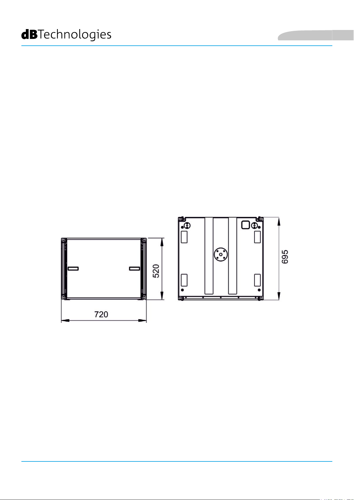
La serie VIO è stata progettata con una particolare attenzione all’ottimizzazione di peso e ingombro.
Il cabinet in legno di ViO S118, rivestito in poliurea, pesa 45,1 kg.
Le misure sono: 720 mm (L), 520 mm (A), 695 mm (P).
Italiano
VIO-S118
8
Cod. 420120259 REV. 1.0
Page 9
Italiano
MECCANICA
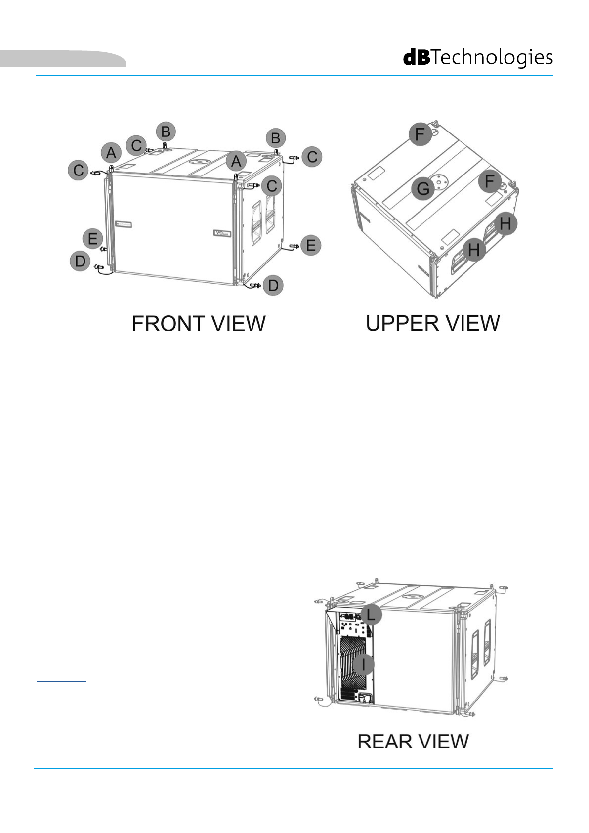
L’ergonomia del subwoofer ed il rapido montaggio in line-array (own o stack) sono garantiti da:
LATO SUPERIORE
A) Staffe a scomparsa frontali per il montaggio di un secondo ViO-S118 (o di un y-bar DRK-210 in congurazione
own).
B) Staffe a scomparsa posteriori per il montaggio di un secondo ViO-S118 (o di un y-bar DRK-210 in
congurazione own, o dell’accessorio GSA-ViOL210 in congurazione stack).
C) Pin per il ssaggio in posizione aperta/chiusa delle staffe a scomparsa [A e B].
LATO INFERIORE
D) Sistema di ancoraggio frontale ad un secondo ViO-S118 (o ad un modulo line-array ViO-L210 own)
E) Sistema di ancoraggio posteriore ad un secondo ViO-S118 (o all’accessorio FSA-ViOL210 in congurazione
own).
TOP
F) fori di aggancio per il ssaggio del y-bar DRK-210 in congurazione stack
G) foro lettato per il montaggio di uno speaker su palo (lettato M20)
H) maniglie (2 per lato) per facilitare il trasporto
I moduli VIO-S118 sono anche provvisti sul lato
posteriore di 1 rain cover [L], per proteggere
l’amplicatore [I] dall’acqua ed operare anche
in condizioni meteo critiche. Nelle illustrazioni
successive, per semplicità, il rain cover non sarà più
mostrato.
Per ulteriori informazioni sul y-bar (vedere la sezione
ACCESSORI) e sugli accessori di montaggio fare
riferimento al manuale relativo.
VIO-S118 Cod. 420120259 REV. 1.0
9
Page 10
Italiano
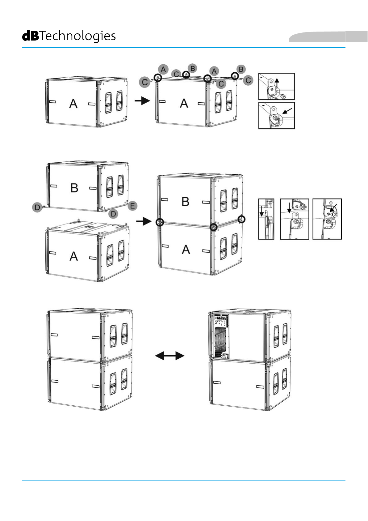
Il montaggio di 2 moduli A e B prevede pochi semplici passi:
• Sul modulo A estrarre i pin [C], alzare le staffe a scomparsa [A] e [B] e ssarle nella nuova posizione coi i pin
[C].
• Estrarre tutti i pin [D] ed [E] nel modulo B, sovrapporlo al modulo A, inserendo le staffe come mostrato.
Fissare quindi il lato anteriore e posteriore dei due moduli con i pin [D] ed [E] del modulo B.
Il sistema di montaggio è simmetrico: lo stesso procedimento vale per la congurazione verticale cardioide.
VIO-S118
Cod. 420120259 REV. 1.0
10
Page 11
Italiano
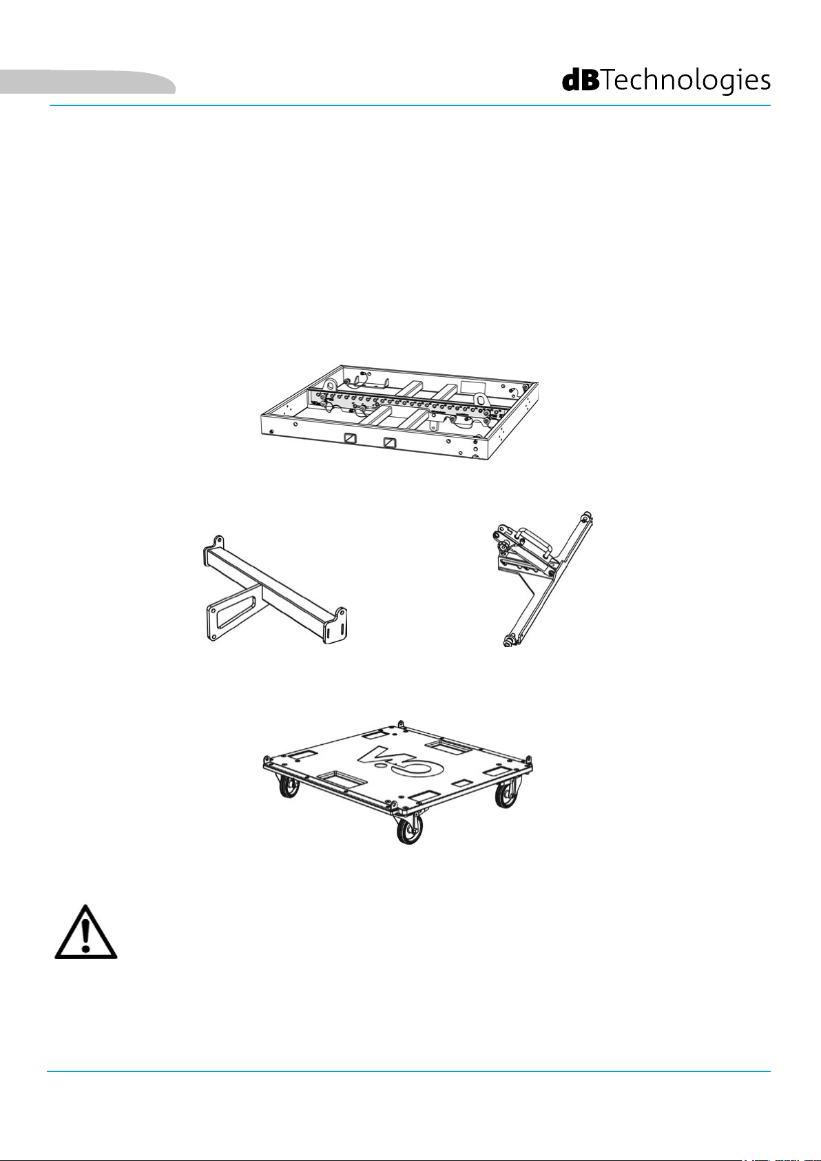
ACCESSORI
Per un rapido montaggio e per la movimentazione, sono previsti come opzionali i seguenti accessori:
• DRK-210, y-bar per l’utilizzo own e stacked di ViO-S118.
• FSA-ViOL210, per l’aggancio in installazione own tra subwoofer ViO-S118 e modulo ViO-L210
• GSA-ViOL210, per l’aggancio in installazione stack tra subwoofer ViO-S118 e modulo ViO-L210
• DO-ViOS118, per la movimentazione di no a 4 subwoofer ViO-S118.
Per ulteriori informazioni consultare la tabella nella pagina successiva, oltre alla documentazione dei
singoli accessori.
FSA-VIOL210
DRK-210
GSA-VIOL210
DO-VIOS118
ATTENZIONE!
• Utilizzare solo gli accessori e le congurazioni indicate nel presente manuale ed operare in accordo a
quanto indicato nei manuali relativi agli accessori.
VIO-S118 Cod. 420120259 REV. 1.0
11
Page 12
Italiano
VIO-S118
12
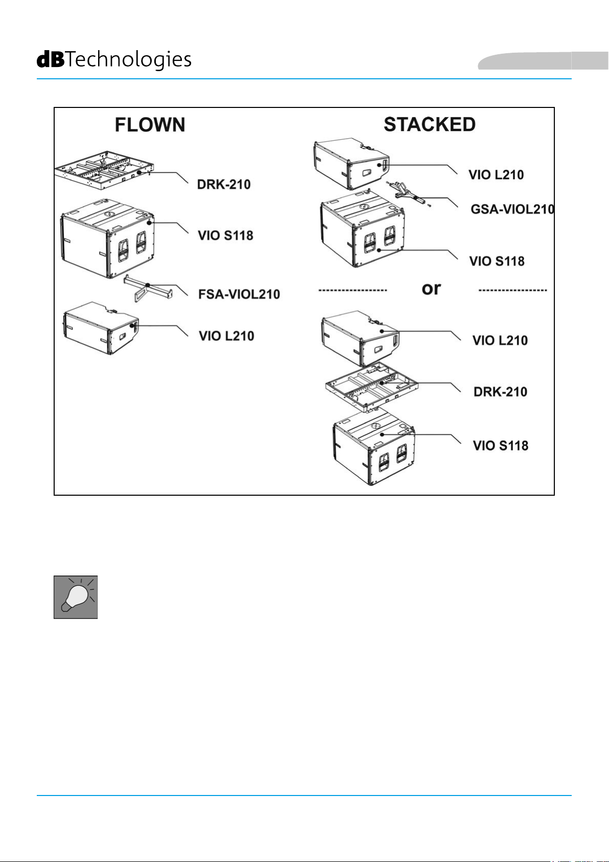
Schema di utilizzo degli accessori di montaggio
• In congurazione own l’angolo fra DRK-210 e ViO-S118 è sso (o°)
• In congurazione own l’angolo fra ViO-S118 e ViO-L210 con l’utilizzo dell’accessorio FSA-
ViOL210 è sso 0°
• In congurazione stack le angolazioni del modulo ViO-L210 con l’utilizzo dell’accessorio
DRK-210 sono: -3°, 0°, +3°. Con l’accessorio GSA-ViOL210 sono -8°, -5°, -3°, 0°, +5°.
Cod. 420120259 REV. 1.0
Page 13
Italiano
CARATTERISTICHE DELLA SEZIONE DI AMPLIFICAZIONE E DI CONTROLLO
L’amplicatore digitale in classe D è il cuore dei
subwoofer VIO-S118.
Permette di erogare no a 1600 W RMS, in modo
silenzioso ed efciente, non necessitando di un
sistema di ventilazione. Il controllo del sistema è
afdato a un potente DSP che rende possibile la
congurazione in modo immediato e veloce.
Grazie alla possibilità di collegamento in rete
con RDNet, i parametri sul pannello possono
essere controllati in remoto, grazie al software
“DBTECHNOLOGIES NETWORK” (vedere il paragrafo
CONTROLLO REMOTO).
Il pannello del DIGIPRO G4 è caratterizzato da:
• Sezione di Input, Output e Controllo
• Sezione di Alimentazione
SEZIONE DI
INGRESSO, USCITA E
CONTROLLO
ATTENZIONE!
• Non ostruire le alette posteriori di
raffreddamento dell’amplicatore.
In caso di surriscaldamento
eccessivo, il volume audio
viene ridotto gradualmente
no alla stabilizzazione termica
del modulo. Il livello viene
ristabilito automaticamente al
raggiungimento della corretta
temperatura di funzionamento.
• Non tentare in nessun modo di
aprire l’amplicatore.
• In caso di malfunzionamento,
interrompere immediatamente
l’alimentazione, scollegando il
modulo dalla rete, e contattare un
riparatore autorizzato.
• Il diffusore viene fornito con un
fusibile già montato per operare
nel range 220-240 V. Se è necessario
operare nel range di tensione 100-
120 V:
1. Disconnettere ogni
connessione, compresa
l’alimentazione.
2. Attendere 5 minuti.
3. Sostituire il fusibile
con quello fornito nella
confezione per il range 100-
120 V.
VIO-S118 Cod. 420120259 REV. 1.0
SEZIONE DI
ALIMENTAZIONE
13
Page 14
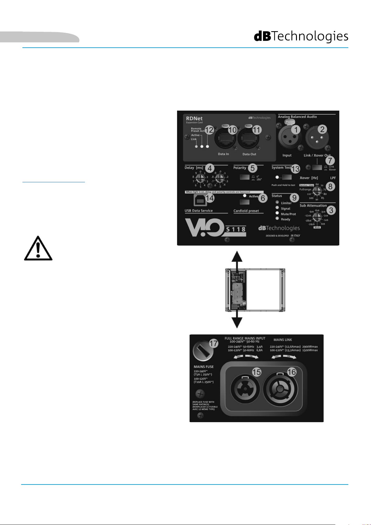
SEZIONE DI INPUT, OUTPUT E DI CONTROLLO
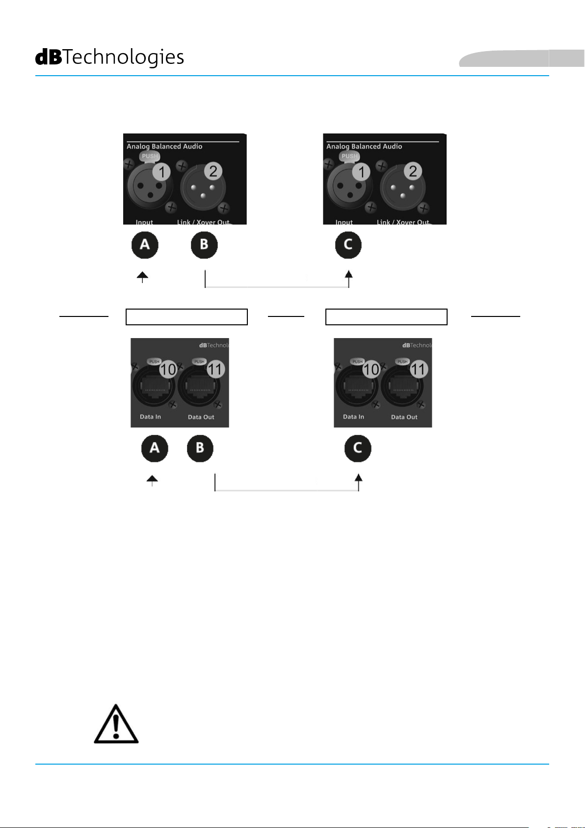
1. INGRESSO (“Balanced audio
Input”)
Ingresso compatibile con cavi
XLR blanciati. E’ utilizzato per il
collegamento con il segnale audio
proveniente dal mixer o da un altro
diffusore.
2. USCITA (“Balanced Audio Link/
Xover). Uscita compatibile con cavi
XLR bilanciati. E’ utilizzata per il
rilancio del segnale ad un altro
subwoofer o agli altri moduli del
line-array in congurazione daisychain (“link”). In alternativa, per
congurazioni che necessitano
dell’applicazione di un crossover
(“Xover”), rilancia un segnale ltrato
alla frequenza impostata [8]. La
scelta del tipo di utilizzo avviene
tramite il selettore [7].
Italiano
3. SUB ATTENUATION
Permette di regolare l’attenuazione del subwoofer agendo sul volume di ingresso. Si consiglia di porre a 0 dB
prima di iniziare il montaggio.
4. CONTROLLO DI DELAY (“Delay” [ms])
I due selettori rotativi permettono di impostare il ritardo del segnale del subwoofer nel range 0-9.9 ms. Il primo
selettore regola il valore intero del ritardo, il secondo quello decimale.
5. SELETTORE DI POLARITA’ (“Polarity”)
Permette di invertire la polarità audio del subwoofer. Può essere utile per allineare la fase tra vari subwoofer
o fra un subwoofer e i moduli line-array. Vedere per ogni ulteriore dettaglio il capitolo PARAMETRI DI
CONFIGURAZIONE.
6. SELETTORE MODALITA’ CARDIOIDE (“Cardioid preset”)
Permette di congurare l’utilizzo cardioide con un solo comando. In caso sia selezionata questa modalità, il led
“Active” è acceso ed i valori di polarità e ritardo risultano by-passati, perchè già preimpostati.
7. SELETTORE DI UTILIZZO “LINK” O “XOVER”
Selettore che determina il tipo di uscita presente al connettore [2].
8. SELETTORE DI FREQUENZA XOVER (“Xover [Hz]”)
Seleziona la frequenza XOVER (60-70-75-80-85-90-100-110-Fullrange) applicata all’uscita [2]. La posizione Service/
User va invece utilizzata per lo stato di aggiornamento del rmware o per richiamare un’impostazione USER (vedi
il manuale di DBTECHNOLOGIES NETWORK). Vedi anche la sezione AGGIORNAMENTO DEL FIRMWARE.
9. LED DI STATO (“Status”)
Led relativi al funzionamento del modulo. Una tabella nella pagina seguente riepiloga e sintetizza il signicato
dei vari LED.
VIO-S118
Cod. 420120259 REV. 1.0
14
Page 15
Italiano
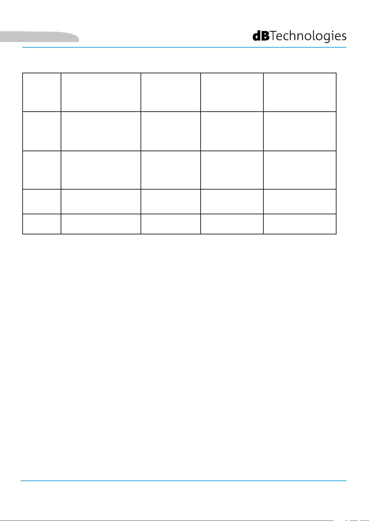
TIPO LED FASE DI ACCENSIONE
DELLO SPEAKER
IN FUNZIONE
NORMALE
WARNING
GENERICO
BLOCCO PER
ANOMALIA DELLO
SPEAKER
LIMITER SPENTO SPENTO, SI
ACCENDE SOLO
IN CASO DI
INTERVENTO
SIGNAL
MUTE/
PROT
READY SPENTO ACCESO FISSO ACCESO FISSO SPENTO
10. INGRESSO DELLA CONNESSIONE DI RETE RDNet (“Data In”)
Per cavi di rete dotati di connettori di tipo etherCON/RJ45.
Collegarlo a dispositivi come RDNet Control 2 o Control 8 per utilizzare il controllo remoto.
SPENTO ACCESO
ACCESO PER QUALCHE
SECONDO
IN PRESENZA DI
SEGNALE
SPENTO LAMPEGGIO
Tabella di segnalazione dei LED di stato
LAMPEGGIO
MOMENTANEO
SEGNALAZIONE
NORMALE DI
AUDIO IN
INGRESSO
MOMENTANEO
LAMPEGGIO CICLICO
CONTINUO
SPENTO
ACCESSO FISSO
11. RILANCIO DELLA CONNESSIONE DI RETE RDNet (“Data Out”)
Compatibile con cavi di rete dotati di connettori di tipo etherCON/RJ45.
Viene utilizzato per il rilancio della rete di controllo remoto ad ulteriori moduli del sistema in congurazione
daisy-chain.
12. LED DI CONTROLLO
Led relativi al funzionamento in rete (RDNet) del modulo.
In particolare, “Link” acceso segnala che la rete RDNet è attiva e ha riconosciuto il dispositivo, “Active” in modalità
lampeggiante che esiste trafco dati, “Remote Preset Active” che tutti i controlli locali sul pannello amplicatore
sono by-passati dal controllo remoto RDNet.
13. SYSTEM TEST
Effettua un test con segnale sweep per vericare l’integrità del woofer. Questo test non va considerato esaustivo,
ma solo un primo controllo nell’analisi di eventuali problematiche.
14. USB DATA SERVICE
Porta di tipo USB B, da utilizzare esclusivamente per l’aggiornamento del rmware del prodotto. Vedi la sezione
“AGGIORNAMENTO DEL FIRMWARE” per ulteriori informazioni.
VIO-S118 Cod. 420120259 REV. 1.0
15
Page 16
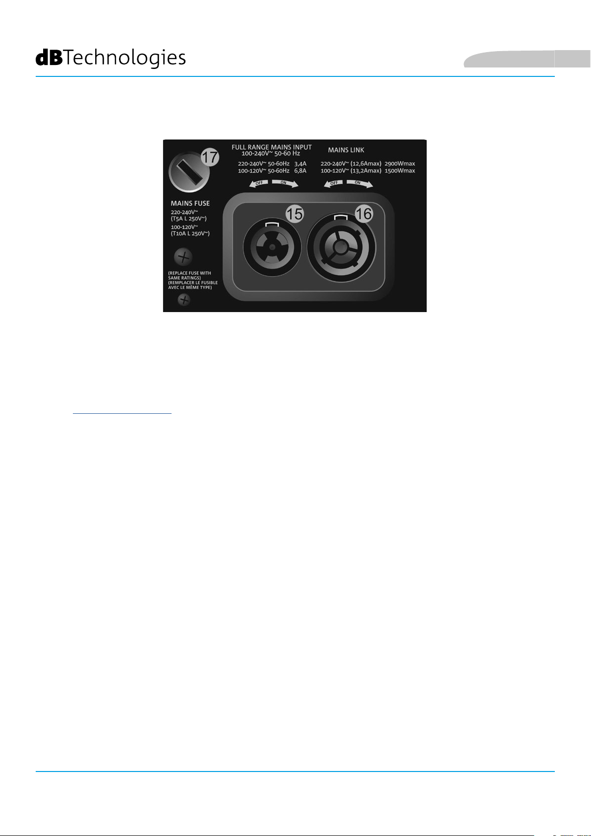
SEZIONE DI ALIMENTAZIONE
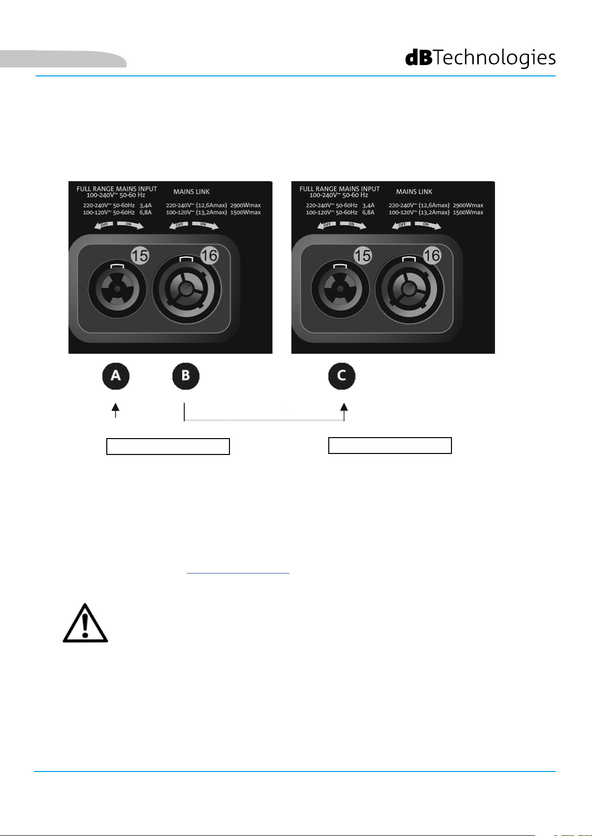
15. CONNETTORE DI ALIMENTAZIONE “MAINS INPUT”
Compatibile con connettore powerCON TRUE1®, l’alimentazione è full range.
Italiano
16. RILANCIO DI ALIMENTAZIONE “MAINS LINK”
Compatibile con connettore tipo powerCON TRUE1® per il rilancio dell’alimentazione ad altri moduli.
Per conoscere il numero massimo di moduli che si possono connettere in un sistema rilanciato, consultare la
sezione SPECIFICHE TECNICHE.
17. FUSIBILE DI RETE
Alloggio per il fusibile di rete.
VIO-S118
16
Cod. 420120259 REV. 1.0
Page 17
Italiano
2. DBTECHNOLOGIES COMPOSER (rev. 6.3.0 o successiva)
Il software dBTechnologies Composer, gratuitamente scaricabile dal sito www.dbtechnologies.com, è lo
strumento per la corretta progettazione di sistemi audio consigliato per tutta la serie VIO.
Suggerisce la soluzione per gli spazi da sonorizzare, indicando l’angolazione dei moduli del line-array per
ottenere la copertura desiderata ed il preset da utilizzare.
Pur essendo uno strumento predittivo, permette comunque una serie di regolazioni manuali per
perfezionare la congurazione in base ad eventuali misure audio effettuate sul campo, o a esigenze
speciche. E’ inne lo strumento efcace per valutare la sicurezza dell’installazione. Grazie infatti a una
simulazione del comportamento statico dei y-bar ed una indicazione delle forze meccaniche in gioco
permette di vericare quanti moduli installare prima di arrivare ad una condizione di sovraccarico.
Le sezioni principali di dBTechnologies Composer sono:
• COMPOSER - vista generale che permette l’inserimento dei dati iniziali di progetto
• LAs PREDICT - con la simulazione, congurazione e verica di sicurezza dei line-array
• SUBs PREDICT - con la simulazione, congurazione e verica di sicurezza dei subwoofer
In questo capitolo vengono evidenziati alcuni dettagli del software relativi al montaggio e alla sicurezza, in
particolare per la congurazione FLOWN di ViO-S118 con i moduli VIOL210.
VIO-S118 Cod. 420120259 REV. 1.0
17
Page 18
Italiano
La sezione LAs PREDICT contiene tutte le informazioni per la corretta congurazione own o stack di un
sistema VIO. Per accedervi occorre completare prima l’inserimento dei dati di progetto, presenti nella
sezione Composer.
Nella sottopagina System Data, vengono suggeriti: l’angolazione dei vari moduli, vari parametri relativi
alla sezione “DSP preset” e l’angolazione del y-bar DRK-210. Quest’ultima angolazione può essere rilevata
sul campo tramite l’utilizzo di un inclinometro laser non incluso, il cui montaggio è illustrato nel manuale
di DRK-210.
VIO-S118
18
Cod. 420120259 REV. 1.0
Page 19
Italiano
Nella sezione Safety Data, è possibile trovare una
simulazione del centro di gravità del sistema own con
Dl’utilizzo del y-bar RK-210.
In particolare, l’utente può scegliere fra i riferimenti
EUROCODE 3 o BGV-C1.
I risultati relativi sono evidenziati in colore verde se sicuri,
in colore rosso se si eccede il carico massimo ammesso
per l’angolazione prescelta (e di cui pertanto è vietato
l’utilizzo).
VIO-S118 Cod. 420120259 REV. 1.0
19
Page 20
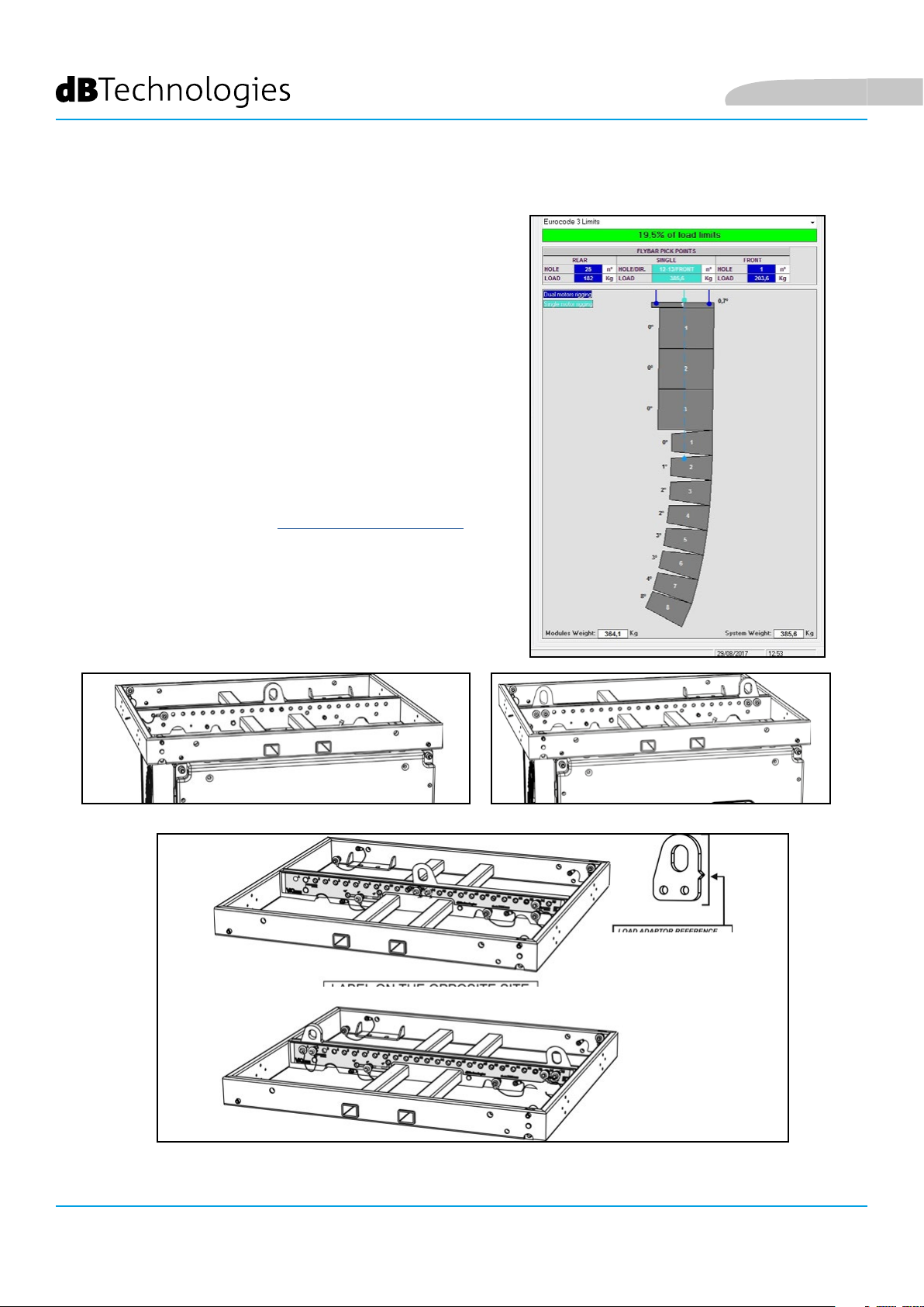
Nel caso in cui, in congurazione own, si utilizzi un solo
motore, “SINGLE” indica la posizione del gancio singolo
da utilizzare su DRK-210 (che prevede posizioni graduate
descritte da un’etichetta posta sul y-bar stesso).
Inoltre esiste un verso “FRONT” o “REAR” relativo a come
si orienta il gancio per il motore.
Nel caso “FRONT” il riferimento (mostrato nella gura
sotto e indicato come LOAD ADAPTOR REFERENCE SIDE),
va posto verso il lato frontale del line-array, in caso
“REAR” va orientato verso il lato posteriore del line array.
In caso si utilizzino due motori invece, i ganci risultano
sempre posti agli estremi del y-bar (in questo caso è
indifferente il verso di posizionamento).
Per ogni altro dettaglio sul software dBTechnologies
Composer, consultare il manuale relativo, scaricabile
gratuitamente all’indirizzo: www.dbtechnologies.com.
Italiano
VIO-S118
20
LOAD ADAPTOR REFERENCE SIDE
ETICHETTA GRADUATA SU UN LATO DEL FLY-BAR
Cod. 420120259 REV. 1.0
Page 21
Italiano
3. COLLEGAMENTI
COLLEGAMENTO E RILANCIO DELL’ALIMENTAZIONE
SUBWOOFER 1
Nell’illustrazione sopra è mostrato un generico caso di collegamento in cui un modulo 1
è sopra al modulo 2. Utilizzare allo scopo cavi con connettori powerCON TRUE1® (non forniti).
• Collegare l’alimentazione del modulo 1 AUTO-RANGE MAINS INPUT (A).
• Rilanciare l’alimentazione dal modulo 1 al modulo 2, collegando l’uscita MAINS LINK (B)
del modulo 1 all’ingresso AUTO-RANGE MAINS INPUT (C) del modulo 2.
• Ripetere quest’ultima operazione no a collegare il numero massimo ammesso di moduli del linearray (vedere il capitolo SPECIFICHE TECNICHE).
SUBWOOFER 2
ATTENZIONE!
• I cavi devono essere opportunamente dimensionati e la progettazione,
installazione e verica dell’impianto devono essere effettuate esclusivamente
da personale qualicato. AEB industriale declina ogni responsabilità in caso
di utilizzo di cavi non idonei, non certicati e non compatibili col corretto
dimensionamento dell’impianto e le normative in vigore per il Paese di utilizzo.
VIO-S118 Cod. 420120259 REV. 1.0
21
Page 22
COLLEGAMENTO E RILANCIO DEL SEGNALE AUDIO E RDNET
SUBWOOFER 1 SUBWOOFER 2
Italiano
Nell’illustrazione sopra è mostrato un generico caso di collegamento in cui un modulo 1
è sopra al modulo 2, questa volta illustrando i collegamenti audio e di rete. Utilizzare allo scopo cavi
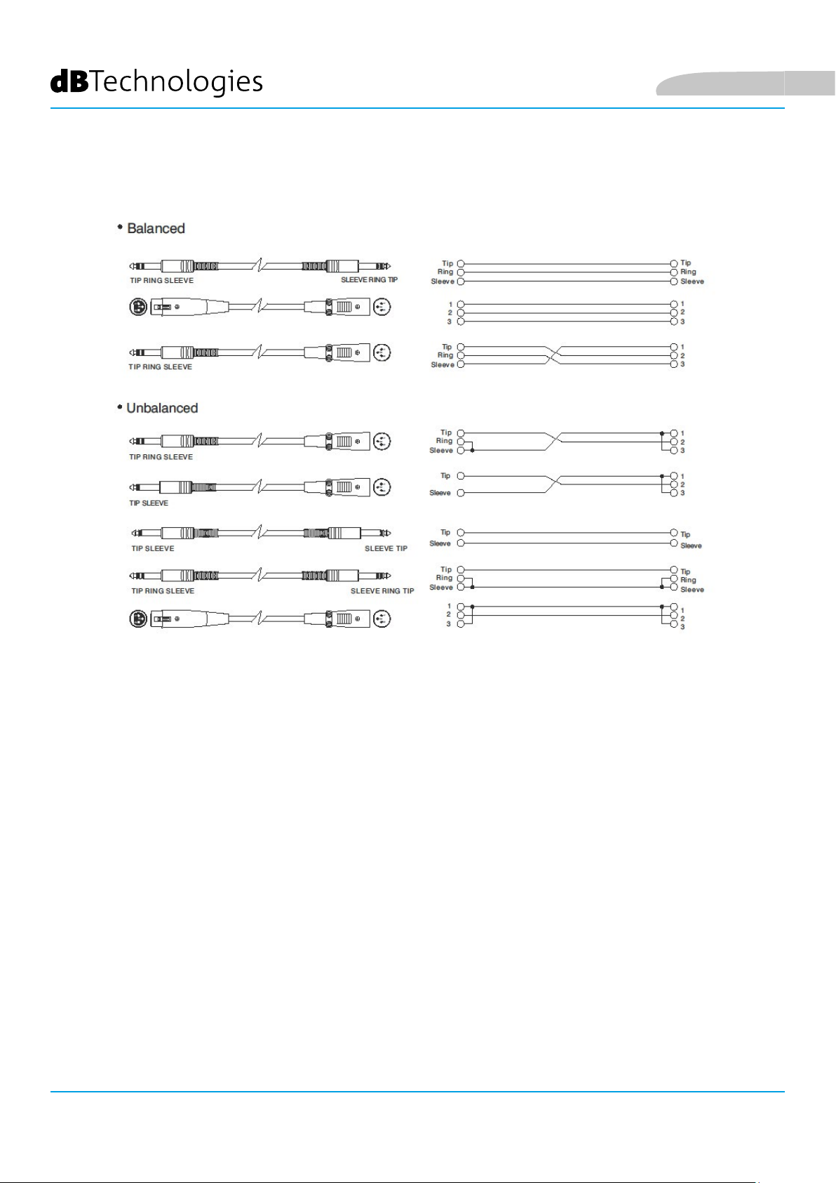
non forniti, con connettori XLR (audio) e etherCON/RJ45 (rete). Per ulteriori informazioni sui tipi di
cavi disponibili confrontare anche l’immagine nella pagina seguente.
• Per la connessione audio, collegare il cavo proveniente da MIXER/LINE all’ingresso BALANCED
• Ripetere l’operazione tra il secondo e il terzo modulo, e così via, no a collegare tutti i moduli del
• Per la connessione di rete, collegare il connettore DATA IN (A) del modulo 1 al controller remoto
VIO-S118
22
AUDIO INPUT (A) del modulo 1 del line array. Rilanciare il segnale tra il primo e il secondo
modulo. A questo scopo collegare l’uscita BALANCED AUDIO OUTPUT/LINK (B) del modulo 1
all’ingresso BALANCED AUDIO INPUT (C) del modulo 2.
line-array.
(RDNet CONTROL 2 oppure RDNet CONTROL 8). Rilanciare il segnale collegando DATA OUT (B) del
modulo 1 a DATA IN (C) del modulo 2.
ATTENZIONE!
• Sostituire i cavi eventualmente danneggiati, per evitare malfunzionamenti ed
una scarsa qualità del suono.
Cod. 420120259 REV. 1.0
Page 23
Italiano
4. CONFIGURAZIONI E CONTROLLO REMOTO
CONFIGURAZIONI CARDIOIDE ED ENDFIRE
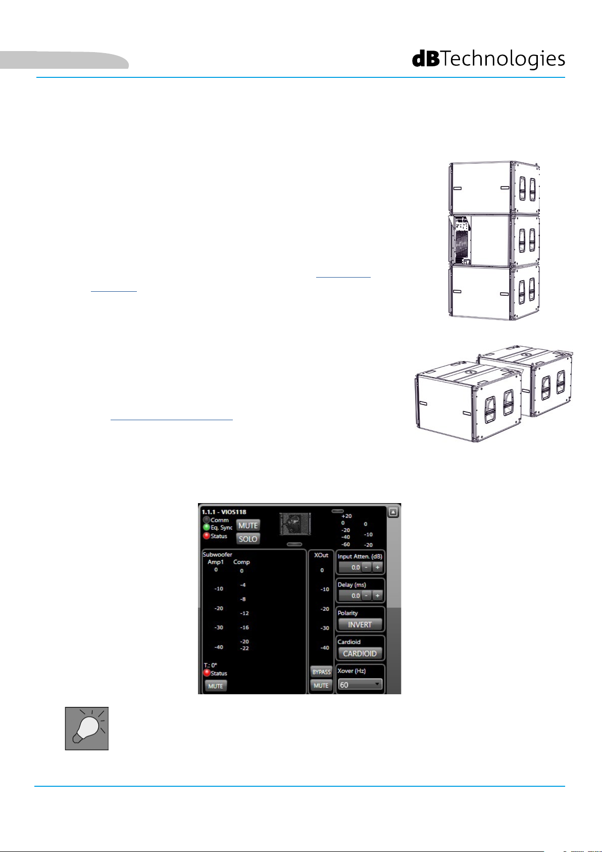
• Per la congurazione cardioide verticale, il limite di montaggio è di 3
subwoofer sovrapposti.
• Utilizzare DBTECHNOLOGIES COMPOSER per impostare i parametri di
progetto.
• Vericare che i parametri locali siano impostati correttamente sui
singoli pannelli amplicatori. Effettuare i collegamenti di rilancio
audio, RDNet e di alimentazione (per i dettagli vedi il capitolo
precedente COLLEGAMENTI). In fase di accensione, prestare
attenzione alla corrente di inrush riportata nelle SPECIFICHE
TECNICHE (es. dimensionamento elettrico di impianto, opportunità di
accensioni differite dei singoli sub).
• In caso di controllo remoto con RDNet e DBTECHNOLOGIES NETWORK
le impostazioni locali vengono by-passate ed il controllo passa al
software.
• Tutti questi parametri possono essere regolati attraverso il controllo
remoto, una volta effettuate correttamente le connessioni RDNet,
attraverso l’utilizzo del software gratuito DBTECHNOLOGIES
NETWORK dalla versione 3.3 in poi (scaricabile gratuitamente dal
sito www.dBTechnologies.com nella sezione DOWNLOAD). Quando
il controllo è remoto, i controlli locali presenti sui pannelli dei moduli
VIO-S118 sono by-passati. Grazie all’utilizzo di questo software,
inoltre è possibile controllare un numero maggiore di parametri
(per ulteriori informazioni si rimanda al manuale completo di
DBTECHNOLOGIES NETWORK).
Le ultime impostazioni scelte e salvate sui subwoofer VIOS118 (con l’utilizzo di
DBTECHNOLOGIES NETWORK), possono essere successivamente richiamate sullo speaker
in assenza di controllo remoto RDNet. E’ sufciente ruotare il rotary XOVER [Hz] sulla
posizione Service/User.
VIO-S118 Cod. 420120259 REV. 1.0
23
Page 24
Italiano
VIO-S118
Cod. 420120259 REV. 1.0
24
Page 25
Italiano
5. INSTALLAZIONE E CONFIGURAZIONE
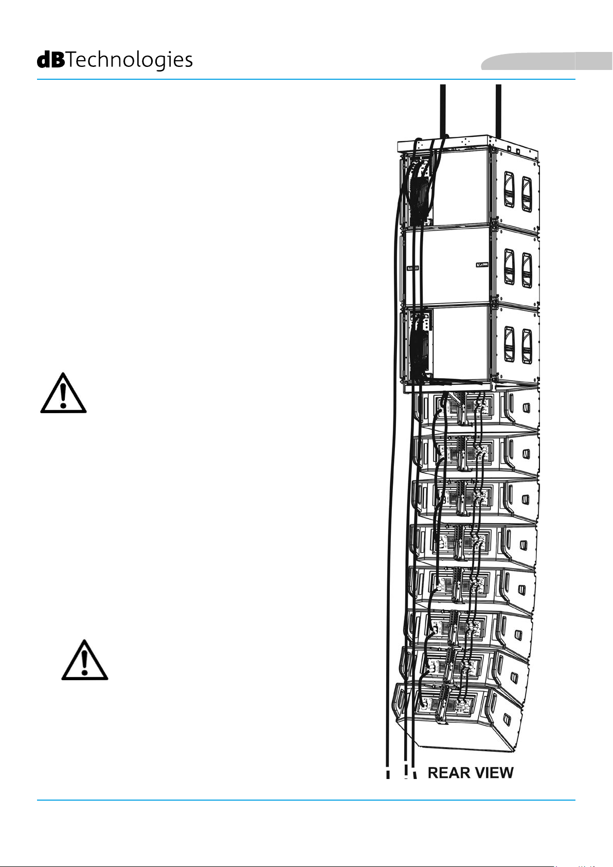
INSTALLAZIONE FLOWN (ESEMPIO DI 1 ARRAY CON 3 VIO-S118 IN
CONFIGURAZIONE CARDIOIDE E 8 VIO-L210)
LE INDICAZIONI DI CABLAGGIO
ILLUSTRATE NELLE FIGURE
SEGUENTI SONO PURAMENTE
INDICATIVE.
• Utilizzare DBTECHNOLOGIES COMPOSER (dalla rev.6.3.0 o successiva) per impostare i parametri di
installazione
• Vericare che i parametri locali dei vari moduli siano impostati correttamente sui singoli pannelli
amplicatori. In alternativa è possibile modicare in tempo reale tutti i parametri da remoto se
si effettua una connessione tramite rete RDNet (DBTECHNOLOGIES NETWORK). In questo caso
comunque è buona norma che le impostazioni iniziali siano replicate sicamente sui moduli
VIO-S118 e VIO-L210 prima dell’installazione. Per altre informazioni vedi la sezione CONTROLLO
REMOTO.
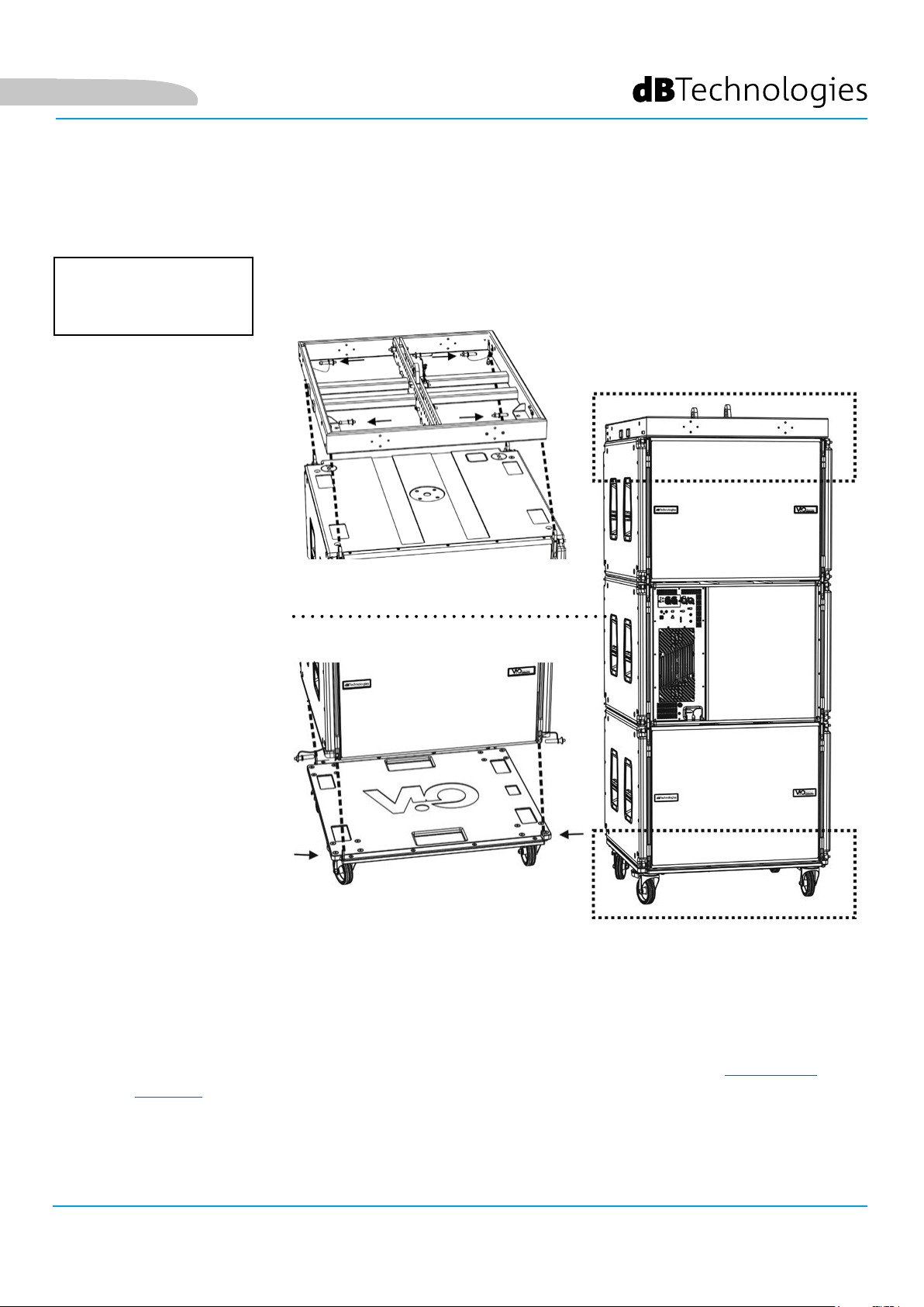
• Trasportare tramite il dolly DO-ViOS118 i 3 subwoofer ViO-S118 montati in congurazione
cardioide, come illustrato (per ulteriori informazioni vedi la sezione MECCANICA del presente
manuale). Porre i freni al carrello. Il y-bar DRK-210 è già stato installato sul top dei subwoofer (in
VIO-S118 Cod. 420120259 REV. 1.0
accordo alle istruzioni relative all’accessorio).
25
Page 26
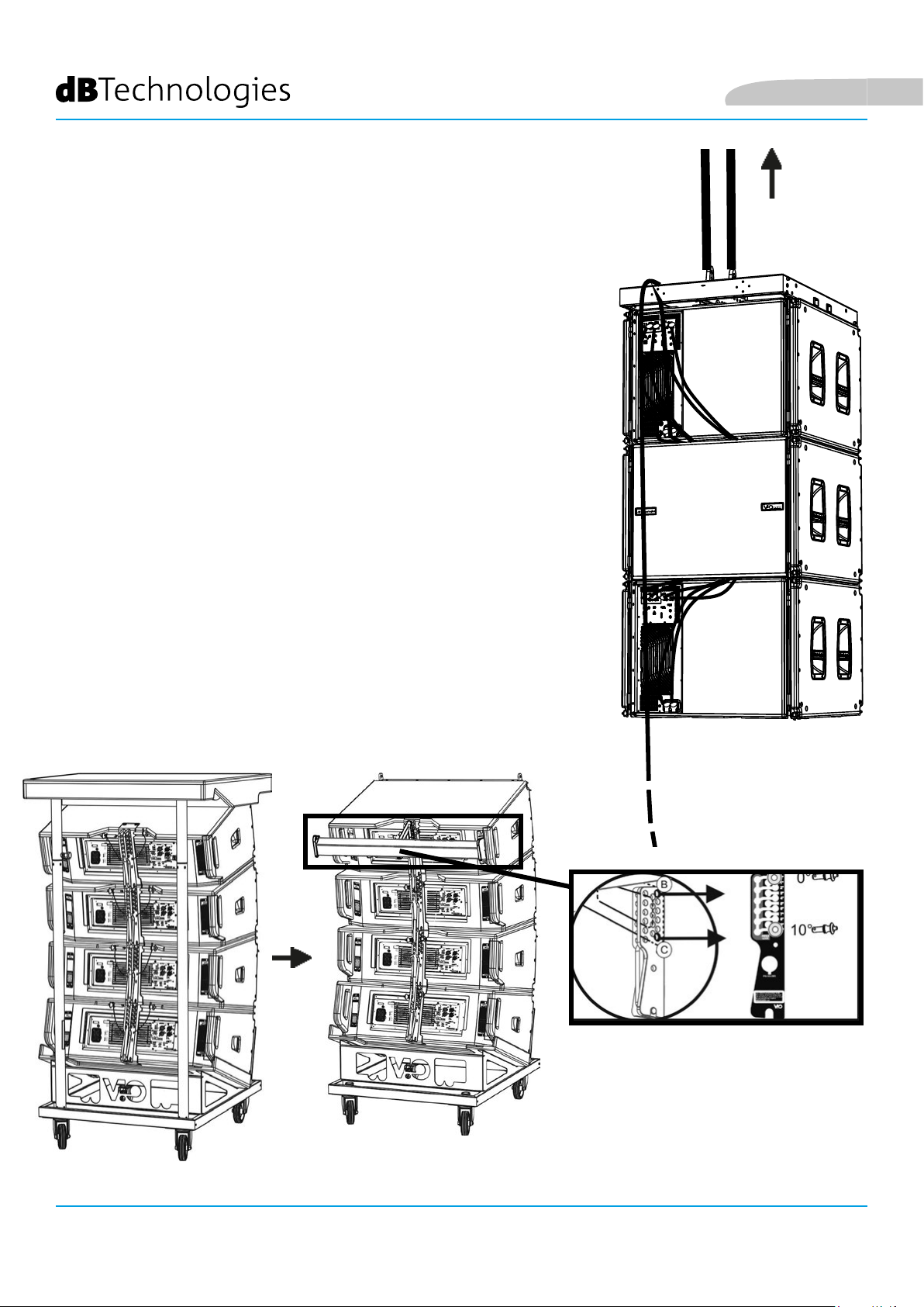
• Effettuare i cablaggi fra i subwoofer come mostrato nel capitolo
COLLEGAMENTI.
• Issare tramite uno o due motori ed opportuni mezzi di rigging
(non forniti) i 3 moduli VIO-S118, così da rimuovere agevolmente il
carrello DO-VIOS118.
• Trasportare tramite DT-VIOL210 i primi 4 moduli ViO-L210 nel punto
in cui il line-array sarà issato. Tenere pronto un secondo carrello con
altri 4 moduli per le fasi successive di montaggio.
• Assicurare i freni alle ruote di DT-VIOL210.
• Sul retro, inserire i bracci mobili nelle staffe come mostrato nel
manuale di ViO-L210.
• Inserire all’interno dei bracci i pin in corrispondenza degli angoli
calcolati in precedenza (per questa operazione non è necessario
sollevare i moduli).
• Effettuare i cablaggi fra i moduli ViO-L210 (vedi il manuale relativo).
• Rimuovere il coperchio superiore e i tubolari sul retro di DT-VIOL210.
• Montare sul retro (nel ViO-L210 superiore) FSA-VIOL210, come
mostrato secondo le prescrizioni delle istruzioni dell’accessorio.
• Posizionare i subwoofer ViO-S118 all’altezza adeguata all’aggancio.
• Completare l’aggancio dei moduli ViO-L210 ai subwoofer ViO-S118
sul lato anteriore e posteriore.
• Togliere i freni alle ruote di DT-VIOL210 vuoto e riporlo in posizione
di riposo.
Italiano
VIO-S118
REAR VIEW
Cod. 420120259 REV. 1.0
26
Page 27
Italiano
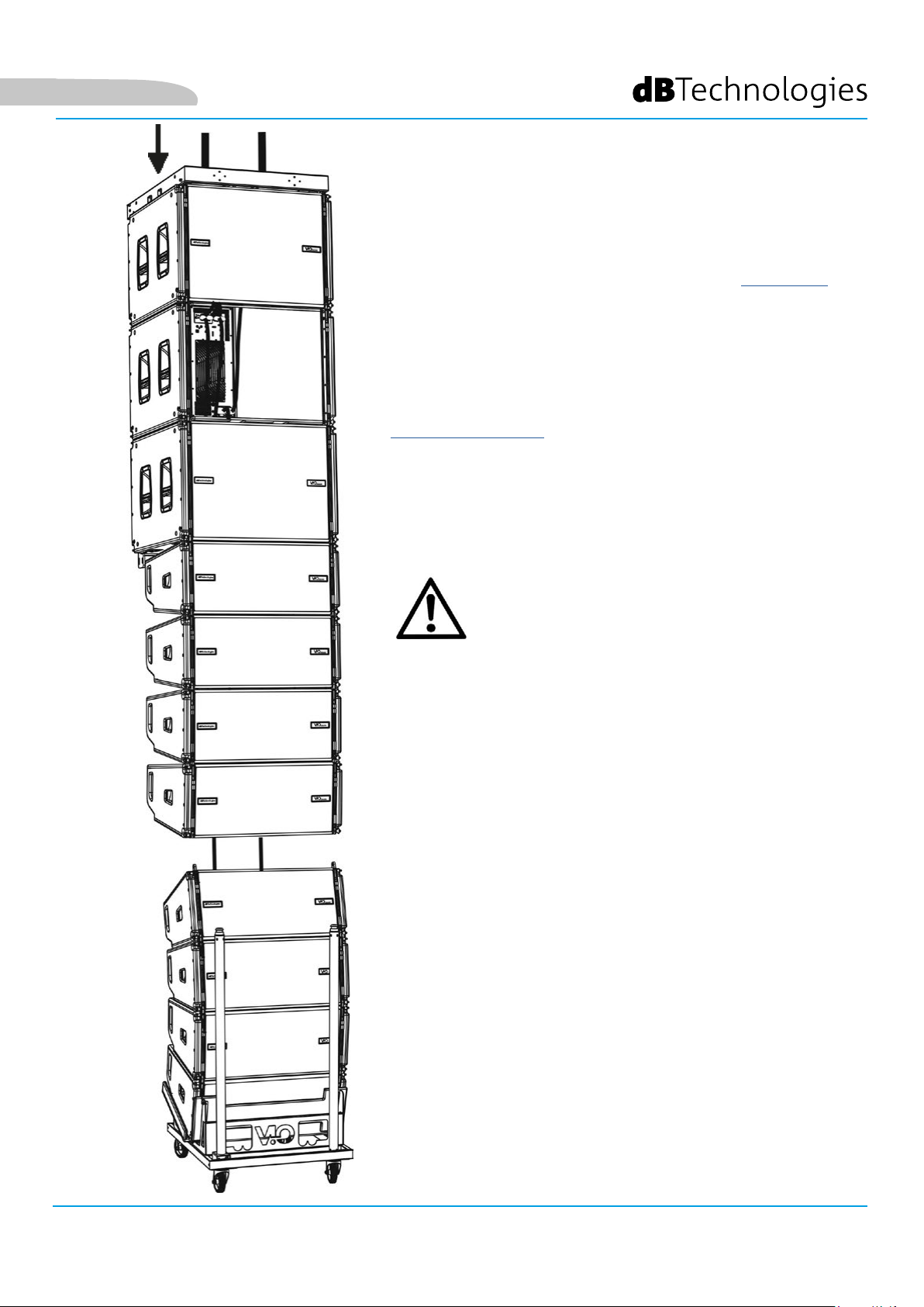
• Portare gli ulteriori 4 moduli con un secondo carrello DTVIOL210 sotto ai primi 4 attualmente sospesi.
• Porre i freni al carrello, effettuare la regolazione degli angoli
come descritto nella fase precedente.
• Rimuovere il coperchio e i tubolari anteriori di DT-VIOL210.
• Far scendere opportunamente i 4 moduli sospesi no ad
agganciarli con il metodo descritto nel paragrafo MECCANICA
del manuale ViO-L210 anteriormente e posteriormente. Prestare
la massima attenzione in questa fase a movimentare il blocco
superiore sospeso.
• Completare i collegamenti di rilancio audio, RDNet e di
alimentazione come da paragra precedenti (per il numero
massimo di rilanci di alimentazione vedere il paragrafo
SPECIFICHE TECNICHE).
ATTENZIONE!
Il massimo carico va sempre vericato preliminarmente con
l’ausilio di dBTechnologies Composer.
DRK-210 è stato progettato per sospendere no a un massimo
di 750 kg con un singolo punto di aggancio.
I componenti di sospensione di VIO L210 permettono
di connettere no a 10 moduli (max 300 kg) senza limiti
sull’angolazione del line array. Ogni altra congurazione,
o informazione sui dati del sistema, come la portata
massima e i punti di aggancio, deve essere vericata prima
dell’installazione con il software dalla rev. 6.3.0 in poi (vedi
il paragrafo relativo in questo manuale d’uso). E’ disponibile
gratuitamente sul sito www.dbtechnologies.com nella sezione
DOWNLOADS.
E’ obbligatorio inoltre l’utilizzo in own di FSA-VIOL210 tra
VIO S118 e VIOL210. Per ogni ulteriore informazione seguire le
istruzioni a corredo dell’accessorio.
VIO-S118 Cod. 420120259 REV. 1.0
27
Page 28
• Sollevare leggermente il line-array per vericare la
correttezza di agganci ed angoli. Eventualmente
vericare con l’inclinometro laser (non fornito) che
l’inclinazione del y-bar corrisponda a quella di progetto.
Vericare che tutti i pin siano interamente inseriti e
bloccati.
• Togliere i freni al carrello DT-VIOL210, chiuderlo e
rimuoverlo.
• Issare con la massima attenzione il line-array così
assemblato.
• Porre in essere tutte le ulteriori tecniche di ssaggio
necessarie ad un utilizzo sicuro e stabile del line-
array, anche in considerazione di eventuali fenomeni
atmosferici a cui può essere sottoposto.
ATTENZIONE!
Italiano
Il prodotto e gli accessori devono essere utilizzati solo da personale
esperto! Assicurarsi che l’installazione sia posizionata in modo stabile e sicuro per scongiurare ogni condizione di pericolo per persone,
animali e/o cose. L’utilizzatore è tenuto a seguire le regolamentazioni
e le leggi cogenti in materia di sicurezza nel Paese in cui si utilizza
il prodotto. Per l’utilizzo in sicurezza, vericare periodicamente la
funzionalità di tutte le parti e l’integrità prima dell’utilizzo.
La progettazione, i calcoli, l’installazione, il collaudo e la manutenzione di sistemi sospesi o stack audio professionali deve essere
effettuata esclusivamente da personale autorizzato. AEB Industriale
non è responsabile per installazioni improprie, effettuate in assenza
dei requisiti di sicurezza.
ATTENZIONE!
• Non utilizzare mai le maniglie, le staffe o
altri elementi del diffusore per sospendere
direttamente i moduli o il sistema!
• In caso di utilizzo all’aperto è sempre
consigliabile ancorare il sistema per
prevenire eventali oscillazioni dovute al
vento o agli agenti atmosferici
VIO-S118
28
Cod. 420120259 REV. 1.0
Page 29
Italiano
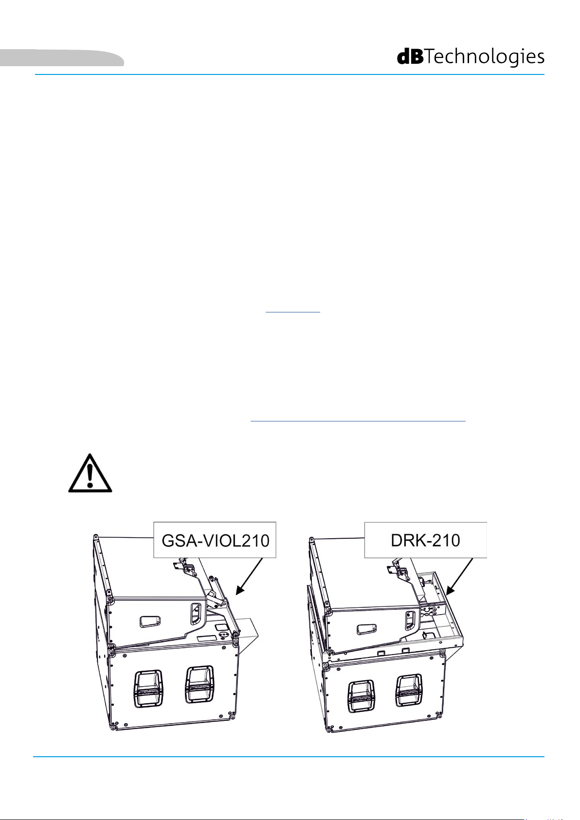
INSTALLAZIONE STACKED (ESEMPIO DI 1 MODULO VIO-L210 su VIO-S118)
• E’ possibile montare al massimo 3 moduli in congurazione stacked su accessorio GSA-
ViOL210. Con DRK-210 6 moduli. Il numero massimo di ViO-S118 è 2.
• E’ possibile utilizzare sia l’accessorio GSA-VIOL210 che DRK-210.
• Utilizzare DBTECHNOLOGIES COMPOSER per impostare i parametri di progetto, per
motivi di sicurezza.
• Porre su SUB S118 (installato su un piano privo di inclinazione) l’accessorio GSA-VIOL210
o DRK-210. Per i dettagli relativi a questo accessorio vericare ulteriori dettagli sul
manuale relativo.
• Aggiungere ad uno ad uno i moduli VIO-L210, con l’angolazione precedentemente
calcolata, come illustrato nel paragrafo MECCANICA.
• Vericare che i parametri locali dei vari moduli siano impostati correttamente
sui singoli pannelli amplicatori. In particolare vericare secondo progetto le
impostazioni di Audio Attenuation, Speaker Coupling e High Frequency Compensation.
In alternativa è possibile modicare in tempo reale anche in un secondo tempo
tutti i parametri da remoto se si effettua una connessione del line-array tramite
rete RDNet (DBTECHNOLOGIES NETWORK). Tuttavia è buona norma che almeno le
impostazioni iniziali di progetto siano replicate sicamente sui moduli VIO-L210 prima
dell’installazione. Vedere la sezione PARAMETRI DSP PRESET E CONTROLLO REMOTO per
ulteriori informazioni.
ATTENZIONE!
• In caso di supercie di appoggio che presenti un’inclinazione anche minima, è
obbligatorio ssare opportunamente con adeguati mezzi meccanici e/o cinghie
l’installazione.
• Per ogni ulteriore informazione sugli accessori mostrati è obbligatorio
consultarne le istruzioni relative
VIO-S118 Cod. 420120259 REV. 1.0
29
Page 30

6. RISOLUZIONE DEI PROBLEMI
Il subwoover non si accende:
1. Vericare la corretta presenza dell’alimentazione a monte dell’impianto.
2. Vericare che l’alimentazione o il collegamento di rilancio di alimentazione sia correttamente inserito.
Il subwoofer si accende ma non emette nessun suono:
1. Vericare che i collegamenti in ingresso del segnale audio o i rilanci del segnale audio siano
correttamente effettuati.
2. Vericare che Sub Attenuation sia impostato a 0 dB.
3. Vericare che la sorgente audio (mixer) sia collegata correttamente ed attiva.
4. Vericare che, in caso di connessione in rete RDNet e controllo con DBTECHNOLOGIES NETWORK, la
funzione MUTE sia disabilitata.
Italiano
Il modulo emette un suono non pienamente soddisfacente.
1. Rivericare il progetto e le speciche di installazione e congurazione tramite DBTECHNOLOGIES
COMPOSER.
2. Vericare che i parametri Xover, Polarity,Delay, Cardioid, siano corretti ed effettivamente replicati sul
pannello di controllo del modulo (soprattutto in caso non si utilizzi il controllo remoto dei moduli).
3. Vericare che, in caso di connessione in rete RDNet e controllo con DBTECHNOLOGIES NETWORK, tutti i
parametri siano impostati correttamente.
VIO-S118
30
Cod. 420120259 REV. 1.0
Page 31

Italiano
7. AGGIORNAMENTO DEL FIRMWARE
È molto importante mantenere aggiornato il rmware del prodotto, per garantirne una piena funzionalità.
Controllare periodicamente il sito http://www.dbtechnologies.com nella sezione “DOWNLOADS”.
1. Scaricare ed installare USB BURNER MANAGER nella sezione “SOFTWARE & CONTROLLER” sul proprio
computer.
2. Scaricare il le .zip dell’ultimo rmware nella sezione “DOWNLOADS” relativa al proprio prodotto.
3. Collegare il prodotto al PC tramite un cavo USB (non fornito) con il connettore del tipo corretto (vedere questo
dettaglio nel capitolo CARATTERISTICHE DELLA SEZIONE DI AMPLIFICAZIONE E DI CONTROLLO).
4. Nella schermata dell’USB BURNER MANAGER, in alto a destra, selezionare “Apertura File”.
5. Selezionare il le del rmware precedentemente scaricato.
6. Seguire le operazioni mostrate a video.
7. Cliccare “AGGIORNA”.
VIO-S118 Cod. 420120259 REV. 1.0
31
Page 32

8. SPECIFICHE TECNICHE
GENERALE
Tipologia: Subwoofer caricato a tromba
DATI ACUSTICI
Risposta in frequenza [- 6 dB]: 36 Hz - frequenza di cuto (dipendente da Xover)
Risposta in frequenza [- 10 dB]: 33 Hz - frequenza di cuto (dipendente da Xover)
Max SPL (1 m): 139 dB
LF: 1 x 18” (Bobina: 4”)
Italiano
Frequenza di crossover: Selezionabile, con step da 10 Hz (da 60 Hz a 110 Hz o FULLRANGE)
AMPLIFICATORE
Tipologia: Digipro® G4
Classe di amplicazione: Classe D
Potenza di amplicazione (RMS) 1600 W
Potenza di amplicazione (Picco): 3200 W
Alimentazione: Full-range
Tecnica di rareddamento: Convezione e ventola interna
Temperatura di utilizzo (ambiente): da -15° a +55° [°C]
PROCESSORE
Controller interno: DSP 28/56 bit 48 kHz
Limiter: Peak, RMS, Termico
VIO-S118
32
Cod. 420120259 REV. 1.0
Page 33

Italiano
INTERFACCIA UTENTE
Led di segnalazione: Limiter, Signal, Mute/prot, Ready
Led di stato (rete RDNet) Link, Active, Remote Preset Active
Controlli
Polarity (0°/180°), Delay (0-9,9 ms), Funzione cardioide, Frequenza di
Xover (
60-70-75-80-85-90-100-110-Fullrange), Sub Attenuation, Test
INGRESSI ED USCITE
Ingressi e rilanci di alimentazione: PowerCON® True In/Link
Ingressi audio: 1x XLR IN bilanciato (isolamento: Floating ADC )
Uscite audio: 1x XLR link OUT bilanciato, HPF Xover audio
Ingressi/uscite RDNet: Data In / Data Out (connettori etherCON®)
USB (aggiornamento del rmware): 1x USB tipo B
SPECIFICHE DI ALIMENTAZIONE (ASSORBIMENTO)
Assorbimento a 1/8 della potenza in
condizioni medie di utilizzo (*):
Assorbimento a 1/3 della potenza in
condizioni massime di utilizzo (**):
Assorbimento con speaker acceso in
assenza di segnale (idle):
1.4 A (220-240V~) - 2.7 A (100-120V~)
3.4 A (220-240V~) - 6.8 A (100-120V~)
35 W
Corrente di inrush:
3 A
Numero di moduli massimo per
linea di alimentazione (**)
1+3 (220-240V~) / 1+1 (100-120V~)
[mains input + mains link]:
* NOTA PER L’INSTALLATORE: Valori riferiti a 1/8 della potenza, in condizioni medie di funzionamento (programma musicale con clipping raro
o assente). Si consiglia per qualsiasi tipo di congurazione di considerarli i valori minimi di dimensionamento.
** NOTA PER L’INSTALLATORE: Valori riferiti a 1/3 della potenza, in condizioni pesanti di funzionamento (programma musicale con frequente
clipping e intervento del limiter). E’ consigliabile il dimensionamento secondo questi valori in caso di installazioni e tour professionali.
VIO-S118 Cod. 420120259 REV. 1.0
33
Page 34

SPECIFICHE MECCANICHE
Materiale: cabinet in legno multistrato - nitura polliurea nera
Griglia: interamente in metallo - lavorazione CNC
Maniglie: integrate (2x lato)
Italiano
Predisposizioni di montaggio con
moduli in own:
Predisposizioni di montaggio con
moduli in stack:
Predisposizioni di montaggio per DRK-210 o FSA-ViOL210
Predisposizioni di montaggio per DRK-210 o GSA-ViOL210
Larghezza: 720 mm (28.34 inch.)
Altezza: 520 mm (20.47 inch.)
Profondità: 695 mm (27.36 inch.)
Peso: 45.1 kg (99.42lbs.)
Le caratteristiche, le speciche e l’aspetto dei prodotti sono soggetti a possibili cambiamenti senza previa
comunicazione. dBTechnologies si riserva il diritto di apportare cambiamenti o miglioramenti nel design o nelle
lavorazioni senza assumersi l’obbligo di cambiare o migliorare anche i prodotti precedentemente realizzati.
VIO-S118
34
A.E.B. Industriale Srl
Via Brodolini, 8
Località Crespellano
40053 VALSAMOGGIA
BOLOGNA (ITALIA)
Tel +39 051 969870
Fax +39 051 969725
www.dbtechnologies.com
info@dbtechnologies-aeb.com
Cod. 420120259 REV. 1.0
Page 35

English
TABLE OF CONTENTSTABLE OF CONTENTS
1. GENERAL INFORMATION .................................................................................................... 36
WELCOME! ....................................................................................................................... 36
PRODUCT OVERVIEW ....................................................................................................... 36
USER REFERENCE .............................................................................................................. 36
MECHANICAL AND ACOUSTICAL FEATURES ................................................................... 37
SIZE AND WEIGHT ................................................................................................................................... 37
MECHANICS ............................................................................................................................................. 38
ACCESSORIES ........................................................................................................................................... 40
FEATURES OF THE AMPLIFIER AND CONTROL SECTIONS .............................................. 42
INPUT, OUTPUT AND CONTROL SECTION .............................................................................................. 43
POWER SUPPLY UNIT SECTION ............................................................................................................... 45
2. DBTECHNOLOGIES COMPOSER (rev. 6.3.0 or later) ......................................................... 46
3. CONNECTIONS ...................................................................................................................... 50
CONNECTION AND POWER DAISY CHAIN ............................................................................................. 50
AUDIO AND RDNET SIGNAL CONNECTION AND DAISY CHAIN ............................................................ 51
4. CONFIGURATIONS AND REMOTE CONTROL .................................................................... 52
CARDIOID AND ENDFIRE CONFIGURATIONS .................................................................. 52
5. INSTALLATION AND CONFIGURATION .............................................................................. 54
FLOWN INSTALLATION (EXAMPLE OF 1 ARRAY WITH 3 VIO-S118 IN .......................... 54
CARDIOID AND CONFIGURATION AND 8 VIO-L210) ...................................................... 54
STACKED INSTALLATION (EXAMPLE OF 1 VIO-L210 MODULE on VIO-S118) ................ 58
6. TROUBLESHOOTING ............................................................................................................ 59
7. FIRMWARE UPDATES ........................................................................................................... 60
8. SPECIFICATIONS ................................................................................................................... 61
GENERAL .................................................................................................................................................. 61
ACOUSTICAL SPECIFICATIONS ................................................................................................................. 61
AMPLIFIER ................................................................................................................................................ 61
PROCESSOR .............................................................................................................................................. 61
USER INTERFACE ...................................................................................................................................... 62
INPUTS AND OUTPUTS ............................................................................................................................ 62
POWER SUPPLY SPECIFICATIONS (ABSORPTION) .................................................................................. 62
MECHANICAL SPECIFICATIONS ............................................................................................................... 63
VIO-S118 Cod. 420120259 REV. 1.0
35
Page 36

English
1. GENERAL INFORMATION
WELCOME!
Thanks for purchasing a product designed and developed in Italy by dBTechnologies! This powerful and easy
to assembly active subwoofer is the result of years of experience in the eld of sound systems. It makes use of
optimized sound, electronic and material research solutions.
PRODUCT OVERVIEW
ViO S118 is the subwoofer for own or stack installation that expands the possibilities of use of the ViO family.
It combines technical innovation and optimized design in a superbly sounding system, packed into a compact
mechanical solution that is quick to install.
The key features of this subwoofer are:
• horn-loaded acoustic conguration
• wooden cabinet with a polyurea nish, to increase surface durability
• a 4-point integrated rigging system for quick assembly/disassembly
• dedicated accessories for handling and installation
• a powerful (1600 W RMS) and silent amplier which allows reaching a SPL peak of 139 dB (at 1 m)
• control entrusted to a powerful 64-bit DSP
• ADC Floating technology, developed for a perfect isolation from interference, noise or hums, of the
audio input
• power, audio and mains daisy chains for optimized wiring
• WPD technology for remote identication of subwoofer positioning
• RDNet control (removable card), predictive and remote management software (DBTECHNOLOGIES
COMPOSER, EASE, EASE FOCUS 3, DBTECHNOLOGIES NETWORK)
USER REFERENCE
To make the most of your VIO amplier, we recommend that you:
• read the quick start user manual included in the package and this user manual thoroughly and keep
• Register your product at http://www.dbtechnologies.com under “SUPPORT”.
• keep proof of purchase and WARRANTY (User manual “section 2”).
VIO-S118
36
this manual during the whole life of the product.
Cod. 420120259 REV. 1.0
Page 37

English
MECHANICAL AND ACOUSTICAL FEATURES
SIZE AND WEIGHT
The VIO series has been designed with particular attention to the optimization of weight and size.
ViO S118 wooden cabinet, coated with polyurea, weighs 45.1 kg.
The dimensions are: 720 mm (L), 520 mm (H), 695 mm (W).
VIO-S118 Cod. 420120259 REV. 1.0
37
Page 38

MECHANICS
English
The subwoofer ergonomics and the quick assembly in (own of stack) line arrays are guaranteed by:
UPPER SIDE
A) Front retractable brackets for installation of a second ViO-S118 (or of a DRK-210 y-bar in own conguration).
B) Rear retractable brackets for installation of a second ViO-S118 (or of a DRK-210 y-bar in own conguration,
or of GSA-ViOL210 accessory in stack conguration).
C) Pins for fastening the retractable brackets in open/closed position [A and B].
LOWER SIDE
D) Front anchoring system to a second ViO-S118 (or another own ViO-L210 line array module)
E) Rear anchoring system to a second ViO-S118 (or to FSA-ViOL210 accessory in own conguration).
TOP
F) hooking holes for fastening of DRK-210 y-bar in stack conguration
G) threaded hole for installation of one speaker on pole (M20 thread)
H) handles (2 per side) for ease of transport
The VIO-S118 modules are also equipped with 1 rain
cover [L] on the rear side, in order to protect the
amplier [I] from water and allow operation even
in critical weather conditions. The rain cover will
be no longer shown in the following drawings, for
simplicity.
For further information regarding the y-bar (see the
ACCESSORIES section) and the assembly accessories,
please refer to the relevant manual.
VIO-S118
38
Cod. 420120259 REV. 1.0
Page 39

English
The assembly of the 2 modules A and B requires a few easy steps:
• On module A remove the pins [C], raise the retractable brackets [A] and [B] and fasten them to the new
position using the pins [C].
• Remove all the pins [D] and [E] from module B, place it on top of module A, inserting the brackets as shown.
Then fasten the front and rear sides of the two modules using the pins [D] and [E] of module B.
The assembly system is symmetrical: the same procedure applies to cardioid vertical conguration.
VIO-S118 Cod. 420120259 REV. 1.0
39
Page 40

ACCESSORIES
The following accessories are provided as options for quick assembly and handling:
• DRK-210, y-bar for own and stacked use of ViO-S118.
• FSA-ViOL210, for hooking in own conguration between ViO-S118 subwoofer and ViO-L210 module
• GSA-ViOL210, for hooking in stack conguration between ViO-S118 subwoofer and ViO-L210 module
• DO-ViOS118, for handling of up to 4 ViO-S118 subwoofers.
For further information, please refer to the table in the following page, as well as to the documentation of
the single accessories.
English
FSA-VIOL210
DRK-210
GSA-VIOL210
DO-VIOS118
VIO-S118
40
WARNING!
• Only use accessories and congurations described in this manual and operate according to the
instructions in the manuals provided with the accessories.
Cod. 420120259 REV. 1.0
Page 41

English
Usage diagram of assembly accessories
• In own conguration the angle between DRK-210 and ViO-S118 is xed (0°)
• In own conguration the angle between ViO-S118 and ViO-L210 using FSA-ViOL210
accessory is xed 0°
• In stack conguration the angles of ViO-L210 module using DRK-210 accessory are: -3°, 0°,
+3°. With GSA-ViOL210 they are -8°, -5°, -3°, 0°, +5°.
VIO-S118 Cod. 420120259 REV. 1.0
41
Page 42

FEATURES OF THE AMPLIFIER AND CONTROL SECTIONS
The class D digital amplier is the heart of the
VIO-S118 subwoofer.
It allows delivering up to 1600 W RMS, silently and
efciently, without ventilation. System is controlled
by a powerful DSP allowing an immediate and
quick conguration.
Thanks to the possibility of a networking
with RDNet, the parameters on the panel
can be remotely controlled through the
“DBTECHNOLOGIES NETWORK” software (refer to
REMOTE CONTROL paragraph).
English
INPUT,
The DIGIPRO G4 panel is made up of:
• Input, Output and Control Section
• Power Supply Unit Section
WARNING!
• Do not obstruct the rear heat sinks
of the amplier. If the module heats
up excessively, the audio volume is
gradually reduced until the module
is thermally stabilised. The audio
is automatically restored when the
normal operating temperature is
reached.
• Never attempt to disassemble the
amplier in any way.
• In the event of a malfunction,
remove power supply immediately
by disconnecting the unit from
the power mains and contact an
authorised repair centre.
OUTPUT AND
CONTROL SECTION
VIO-S118
42
• The fuse installed at the factory is
rated for operation in the 220-240
V voltage range. If you need to
operate the speaker in the 100-120
V range:
1. Disconnect all connections,
including the power supply
connection.
2. Wait 5 minutes.
3. Replace the fuse with the
fuse rated for the 100-120 V
range, which is included in
the package.
Cod. 420120259 REV. 1.0
UNIT SECTION
POWER SUPPLY
Page 43

English
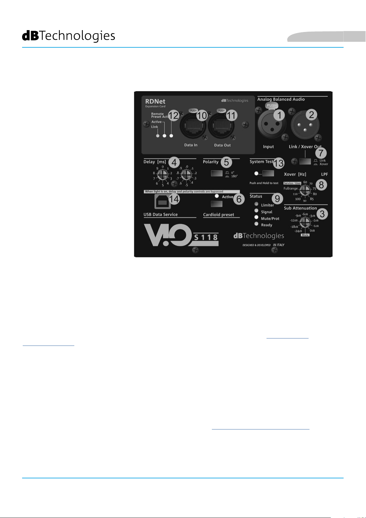
INPUT, OUTPUT AND CONTROL SECTION
1. INPUT (“Balanced audio Input”)
Input compatible with balanced XLR
cables. Used for connection of the
audio signal coming from the mixer
or from another speaker.
2. OUTPUT (“Balanced Audio Link/
Xover). Output compatible with
balanced XLR cables. Used to link
the signal to another subwoofer or
to the other line-array modules in
daisy-chain (“link”) conguration.
As an alternative, for congurations
that require the application of a
crossover (“Xover”), it links a ltered
signal at the set frequency [8]. The
use type selection is carried out
through the selector [7].
3. SUB ATTENUATION
Allows adjusting the attenuation of the subwoofer using the input volume. We recommend to set to 0 dB before
starting assembly.
4. DELAY CONTROL (“Delay” [ms])
The two rotary switches allow setting the subwoofer signal delay within the 0-9.9 ms range. The rst switch
adjusts delay total value, the second one the decimal value.
5. POLARITY SWITCH ("Polarity")
Allows reversing subwoofer audio polarity. It can prove useful to align the phase among the different subwoofers
or between a subwoofer and the line-array modules. For further information, refer to CONFIGURATION
PARAMETERS.
6. CARDIOID MODE SWITCH ("Cardioid preset")
Allows conguring the cardioid use with a single command. If this mode is selected, the "Active" LED is ON and
the polarity and delay values are by-passed, as they are already preset.
7. “LINK” OR “XOVER” USE SWITCH
Switch that determines the type of output present at connector [2].
8. XOVER FREQUENCY SWITCH (“Xover [Hz]”)
It selects the XOVER frequency (60-70-75-80-85-90-100-110-Fullrange) applied to output [2]. The Service/User
position must be used for the rmware update status or to recall a USER setting (refer to the DBTECHNOLOGIES
NETWORK manual). Refer also to the FIRMWARE UPDATE section.
9. STATUS LEDs ("Status")
LEDs relating to module operation. A table in next page summarizes the meaning of the different LEDs.
VIO-S118 Cod. 420120259 REV. 1.0
43
Page 44

English
LED TYPE SPEAKER
TURN-ON PHASE
IN NORMAL
FUNCTION
GENERAL
WARNING
BLOCK FOR
SPEAKER
MALFUNCTION
LIMITER OFF OFF, IT TURNS
ON ONLY
IN CASE OF
TRIGGERING
SIGNAL
MUTE/
PROT
READY OFF STEADY ON STEADY ON OFF
10. RDNet NETWORK CONNECTION INPUT ("Data In")
For network cables with etherCON/RJ45 connectors.
Connect it to devices like RDNet Control 2 or Control 8 to use the remote control.
OFF ON
ON FOR A FEW
SECONDS
IN THE PRESENCE
OF A SIGNAL
OFF TEMPORARY
Table of the status LED signals
TEMPORARY
FLASHING
NORMAL
SIGNAL OF
INPUT
AUDIO
FLASHING
CONTINUOUS CYCLIC
FLASHING
OFF
STEADY ON
11. RDNet NETWORK CONNECTION DAISY CHAIN ("Data Out")
Compatible with network cables with etherCON/RJ45 connectors.
It is used for the remote control network daisy chain to further system modules in daisy-chain conguration.
12. CONTROL LEDs
LEDs relating to module network operation (RDNet).
In particular, if "Link" is on the RDNet network is active and has acknowledged the device, if "Active" is ashing
there is data trafc, if "Remote Preset Active" is on all local control on the amplier panel are by-passed by the
RDNet remote control.
13. SYSTEM TEST
It carries out a test with sweep signal to check woofer integrity. This test must not be considered as thorough, but
just a rst check in the analysis of any issues.
14. SERVICE DATA USB PORT
It is a USB B port to be used only for product rmware update. For further information refer to "FIRMWARE
UPDATE".
VIO-S118
44
Cod. 420120259 REV. 1.0
Page 45

English
POWER SUPPLY UNIT SECTION
15. “MAINS INPUT” POWER CONNECTOR
Compatible with powerCON TRUE1® connector, the power supply is full range.
16. “MAINS LINK” POWER DAISY CHAIN
Compatible with powerCON TRUE1® connector for power daisy chain to other modules.
To nd the maximum number of modules that can be connected in a re-linked system, see the TECHNICAL
SPECIFICATIONS section.
17. NETWORK FUSE
Housing for the network fuse.
VIO-S118 Cod. 420120259 REV. 1.0
45
Page 46

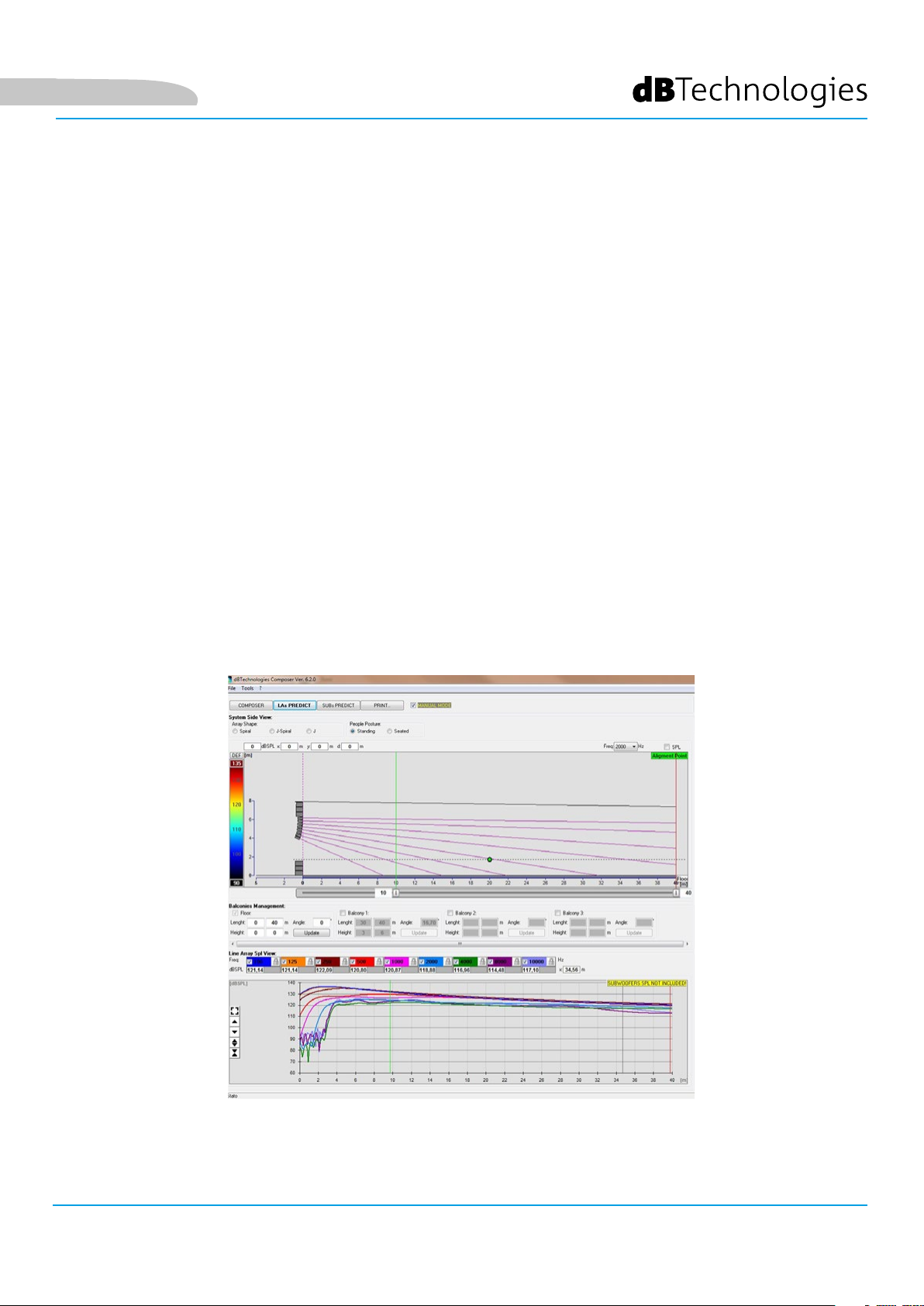
2. DBTECHNOLOGIES COMPOSER (rev. 6.3.0 or later)
dBTechnologies Composer software, available for free download from www.dbtechnologies.com, is a tool
for the proper designing of the audio systems, recommended for the entire VIO series.
It offers a solution for the spaces to sonorize, indicating the angle of the line-array modules in order to
achieve the desired coverage and the preset to use.
Besides being a predictive instrument, it also allows several manual adjustments to further improve the
conguration based on possible audio measurements made on the eld or on special needs. It is also
the effective tool to assess installation safety level. In fact, thanks to the simulation of the y-bar's static
behaviour and an indication of the mechanical forces at play, it allows verifying how many modules should
be installed before reaching an overload condition.
The main sections of dBTechnologies Composer are:
• COMPOSER - overview allowing to enter design start data
• LAs PREDICT - with the simulation, conguration and safety check of the line-arrays
• SUBs PREDICT - with the simulation, conguration and safety check of the subwoofers
English
This chapter describes some of the software's details relating to installation and safety, in particular for the
FLOWN conguration of ViO-S118 with VIOL210 modules.
VIO-S118
46
Cod. 420120259 REV. 1.0
Page 47

English
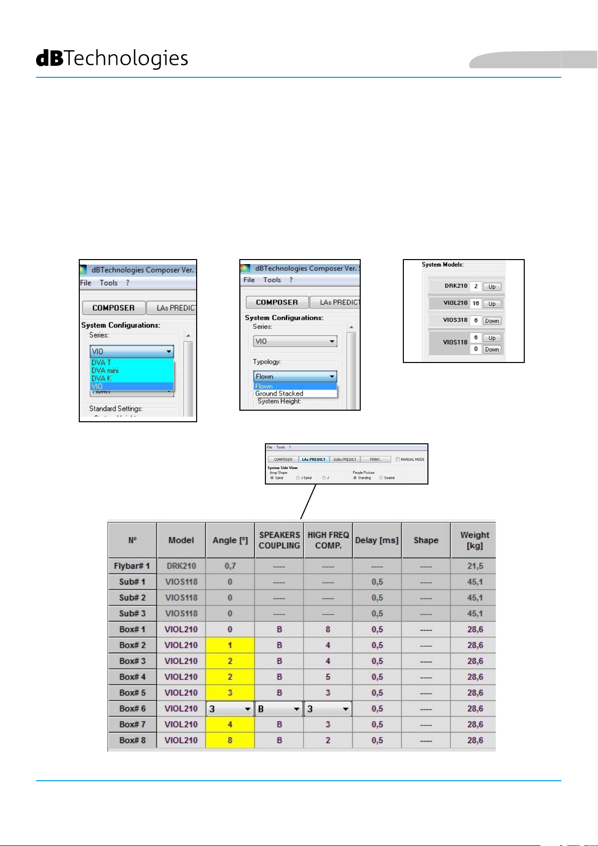
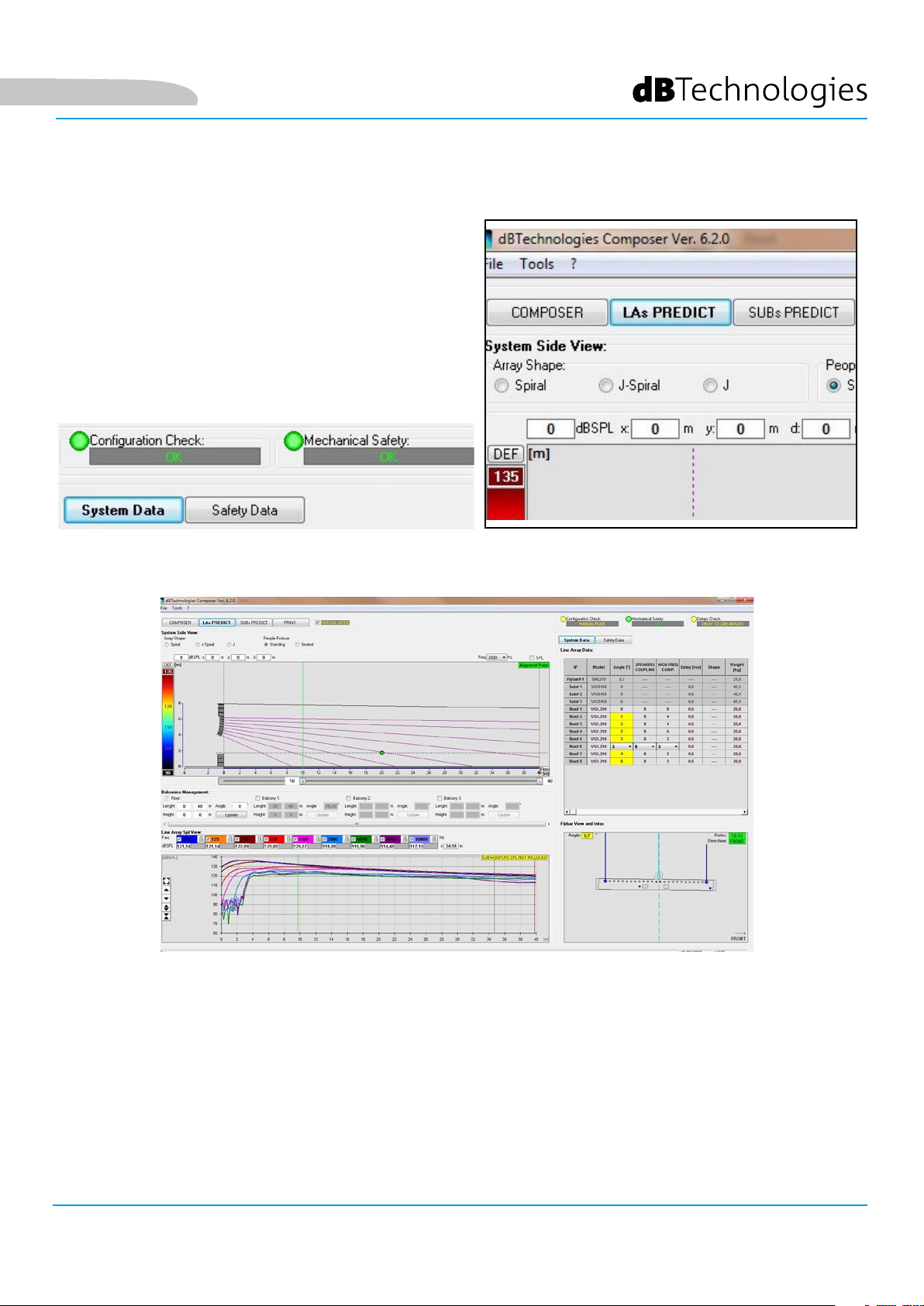
The LAs PREDICT section contains all the information necessary for the proper conguration, own or
stack, of a VIO system. To access it, you need to rst enter the project's data, included in the Composer
section.
The System Data sub-page provides the following suggestions: the angulation of the various modules,
various parameters relating to the “DSP preset” section and the angulation of the DRK-210 y-bar. This last
angulation can be detected on the eld with the use of a laser inclinometer, not included, the assembly of
which is illustrated in the DRK-210 manual.
VIO-S118 Cod. 420120259 REV. 1.0
47
Page 48

In the Safety Data section, you can nd a simulation of the
own system's centre of gravity with the use of RK-210
y-bar.
In particular, the user can choose between EUROCODE 3
or BGV-C1 references.
The related results are shown in green, if safe, and in red,
if the maximum permissible load for the chosen angle is
being exceeded (and which is therefore forbidden to use).
English
VIO-S118
48
Cod. 420120259 REV. 1.0
Page 49

English
In the event that only one engine is being used in a own
conguration, “SINGLE” indicates the position of the
single hook to use on DRK-210 (which requires graduated
positions described by a label placed on the y-bar).
In addition, there is a “FRONT” or “REAR” direction for
directing the hook for the engine.
In the case of “FRONT”, the reference (shown in the gure
below and shown as LOAD ADAPTOR REFERENCE SIDE),
should be placed toward the front of the line array, in the
case of “REAR”, it should be directed toward the rear of
the line array.
If instead two engines are used, the hooks should always
be placed at the ends of the y-bar (in this case, the
direction of the placement is irrelevant).
For any other information on the dBTechnologies
Composer software, see the relevant manual, available for
free download from: www.dbtechnologies.com.
LOAD ADAPTOR REFERENCE SIDE
GRADUATED LABEL ON A SIDE OF THE FLY-BAR
VIO-S118 Cod. 420120259 REV. 1.0
49
Page 50

3. CONNECTIONS
CONNECTION AND POWER DAISY CHAIN
English
SUBWOOFER 1
The gure above shows a general connection where a module 1
is over module 2. For this purpose, use cables with powerCON TRUE1® connectors (not provided).
• Connect the power supply of module 1 AUTO-RANGE MAINS INPUT (A).
• Link the power supply from module 1 to module 2 connecting the output MAINS LINK (B) of module
1 to the input AUTO-RANGE MAINS INPUT (C) of module 2.
• Repeat this procedure until connecting the maximum permitted number of the line-array module
(refer to section SPECIFICATIONS).
SUBWOOFER 2
WARNING!
• The cables must be properly sized and the system’s design, installation and
testing should be performed by qualied personnel only. AEB industriale declines
any responsibility in case of cables that are non-compliant, uncertied and
incompatible with the proper layout of the system and the regulations in force
for the country of use.
VIO-S118
50
Cod. 420120259 REV. 1.0
Page 51

English
AUDIO AND RDNET SIGNAL CONNECTION AND DAISY CHAIN
SUBWOOFER 1 SUBWOOFER 2
The gure above shows a general connection where a module 1
is over module 2 as well as the audio and network connections. To this end, use the not supplied
cables with XLR (audio) and etherCON/RJ45 (network) connectors. For further information on the
available types of cables, refer also to the image in next page.
• For the audio connection, connect the cable originating from MIXER/LINE to the BALANCED
AUDIO INPUT (A) of module 1 of the line array. Re-link the signal between the rst and the
second module. For this purpose, connect the output BALANCED AUDIO OUTPUT/LINK (B) of
module 1 to the BALANCED AUDIO INPUT (C) of module 2.
• Repeat the operation between the second and the third module and so on, until all modules of
the line array are connected.
• For network connection, connect DATA IN connector (A) of module 1 to remote controller (RDNet
CONTROL 2 or RDNet CONTROL 8). Re-link the signal by connecting DATA OUT (B) of module 1 to
DATA IN (C) of module 2.
WARNING!
• Replace any damaged cable to prevent malfunctioning and sound poor
quality.
VIO-S118 Cod. 420120259 REV. 1.0
51
Page 52

4. CONFIGURATIONS AND REMOTE CONTROL
CARDIOID AND ENDFIRE CONFIGURATIONS
• For vertical cardioid conguration, the assembly limit is 3 overlapping
subwoofers.
• Use DBTECHNOLOGIES COMPOSER to set project parameters.
• Make sure that the local parameters are correctly set on the single
amplier panels. Make the audio daisy-chain, RDNet and power
connections (for further details, see the previous CONNECTIONS
chapter). In turn-on phase, pay attention to inrush current, written in
TECHNICAL SPECIFICATIONS chapter (e.g. sizing electrical installation,
evaluating a delayed turn-on of each subwoofer).
• In case of remote control with RDNet and DBTECHNOLOGIES
NETWORK, local settings are by-passed and control is shifted to
software.
English
• All these parameters can be adjusted with the remote control, once
the RDNet connections have been properly made, using the free
DBTECHNOLOGIES NETWORK software from version 3.3 onwards
(free to download from www.dBTechnologies.com in the Downloads
section). When using the remote control, the local controls on the
panels of the VIO-S118 modules are by-passed. Using this software,
you can control a larger number of parameters (for more information,
please refer to the full DBTECHNOLOGIES NETWORK manual).
VIO-S118
52
Last settings stored on VIOS118 subwoofers (using DBTECHNOLOGIES NETWORK software),
can be recalled later on the speaker, without RDNet remote control. To do this, turn the
rotary XOVER [Hz] on Service/User position.
Cod. 420120259 REV. 1.0
Page 53

English
VIO-S118 Cod. 420120259 REV. 1.0
53
Page 54

5. INSTALLATION AND CONFIGURATION
FLOWN INSTALLATION (EXAMPLE OF 1 ARRAY WITH 3 VIO-S118 IN
CARDIOID AND CONFIGURATION AND 8 VIO-L210)
THE CONNECTIONS SUGGESTED
IN THE FOLLOWING PICTURES
ARE FOR INFORMATION ONLY.
English
• Use DBTECHNOLOGIES COMPOSER (from rev.6.3.0 or later) to set installation parameters
• Make sure that the local parameters of the different modules are correctly set on the single
• Transport through DO-ViOS118 dollies the 3 ViO-S118 subwoofers tted in cardioid conguration,
VIO-S118
54
amplier panels. As an alternative, all parameters can be remotely edited in real time if the
connection is carried out through the RDNet network (DBTECHNOLOGIES NETWORK). In this case
it is also good practice to physically replicate the initial settings on the VIO-S118 and VIO-L210
modules before the installation. For further information see the REMOTE CONTROL section.
as shown (for further information, see MECHANICS section of this manual). Place brakes to the
dolly. The DRK-210 y-bar has already been installed on subwoofer top (in accordance with the
accessory instructions).
Cod. 420120259 REV. 1.0
Page 55

English
• Carry out wiring between the subwoofers as explained in
CONNECTIONS chapter.
• Lift the 3 VIO-S118 modules using one or two engines and the
appropriate means for rigging (not provided), so as to easily remove
the DO-VIOS118 dolly.
• Transport, through DT-VIOL210, the rst 4 ViO-L210 modules to the
spot in which the line array will be lifted. Have a second dolly ready
with other 4 modules for the following assembly stages.
• Fix the brakes on the DT-VIOL210 wheels.
• On the back, insert the movable arms into the brackets as shown in
the ViO-L210 manual.
• Insert the pins corresponding to the previously calculated angles
inside the arms (for this operation, you do not need to lift the
modules).
• Carry out wiring between ViO-L210 modules (see the relevant
manual).
• Remove the top cover and the tubes on the back of DT-VIOL210.
• Fit FSA-VIOL210 on the back (in the upper ViO-L210) as shown,
according to the accessory instructions.
• Position ViO-S118 subwoofers at the height suitable for the hook.
• Complete hooking of ViO-L210 modules to ViO-S118 subwoofers on
front and rear side.
• Remove the brakes from the empty DT-VIOL210 wheels and put it
back in the rest position.
REAR VIEW
VIO-S118 Cod. 420120259 REV. 1.0
55
Page 56

English
• Bring the additional 4 modules with a second DT-VIOL210 dolly
under the rst 4, currently suspended.
• Apply brakes to the dolly and adjust the angles as described in
the previous step.
• Remove the cover and the tubes on the front of DT-VIOL210.
• Properly lower the 4 suspended modules and hook them as
described in the MECHANICS paragraph of ViO-L210 manual
for both front and rear. Pay careful attention to this step when
moving the upper suspended block.
• Complete audio, RDNet and power supply re-link connections
as described in the previous paragraphs. To nd the maximum
number of power connections in a re-linked system, see the
TECHNICAL SPECIFICATIONS section.
WARNING!
The maximum load must always be checked in advance using
dBTechnologies Composer.
DRK-210 was designed for the suspension of up to 750 kg with a
single hooking point.
The VIO L210 suspension components allow to connect up to
10 modules (300 kg max) without limiting the angulation of the
line array. Any other conguration or information regarding
the system's data, such as the maximum capacity and hooking
points, must be veried prior to the installation using the
software from rev. 6.3.0 onwards (see the relevant paragraph in
this user manual). It is available for free on the website www.
dbtechnologies.com under the DOWNLOADS section.
Moreover, it is mandatory to use FSA-VIOL210 own between
VIO S118 and VIOL210. For further information refer to the
instructions supplied with the accessory.
VIO-S118
56
Cod. 420120259 REV. 1.0
Page 57

English
• Slightly lift the line array to verify the correctness of
hooks and angles. If necessary, check with a laser
inclinometer (not provided) that the inclination of the y-
bar corresponds to the one in the project. Check that all
the pins have been fully inserted and are locked.
• Remove the brakes from the DT-VIOL210 dolly, close it
and remove it.
• Lift the assembled line array with maximum care.
• Implement any other fastening technique necessary for
the safe and stable use of the line array, also considering
any atmospheric phenomena it may be exposed to.
WARNING!
The product and accessories must be handled by experienced personnel only! Make sure that the installation is positioned in a stable
and safe manner in order to avoid hazardous conditions for people,
animals and/or objects. The user is required to follow regulations
and mandatory laws on safety of the country in which the product
is used. For safe use, regularly check the operation of all parts and
integrity before use.
Design, calculations, installation, testing and maintenance of suspended systems or professional audio stacks must be performed by
authorized personnel only. AEB Industriale is not responsible for
improper installations, non-compliant with safety requirements.
WARNING!
• Never use the handles, the brackets or other
elements of the speaker to directly suspend
the modules or the system!
• In case of outdoor use, it is recommended
to anchor the system to prevent any
oscillations due to wind or weather
conditions
VIO-S118 Cod. 420120259 REV. 1.0
57
Page 58

English
STACKED INSTALLATION (EXAMPLE OF 1 VIO-L210 MODULE on VIO-S118)
• It is possible to install a maximum of 3 modules in stacked conguration on the GSA-
ViOL210 accessory. 6 modules with DRK-210. The maximum number of ViO-S118 is 2.
• It is possible to use both GSA-VIOL210 and DRK-210 accessory.
• Use he DBTECHNOLOGIES COMPOSER to set the project parameters, for safety reasons.
• Position GSA-VIOL210 or DRK-210 accessory (installed on a at surface) on SUB S118. For
further details on this accessory, refer to the relevant manual.
• Add VIO-L210 modules one by one, with the previously-calculated angle, as shown in
MECHANICS paragraph.
• Make sure that the local parameter of the different modules are correctly set on the
single amplier panels. In particular, verify according to the project, Audio Attenuation,
Speaker Coupling and High Frequency Compensation settings. As an alternative, all
parameters can be remotely edited in real time or at a later stage in case of line-array
connection through the RDNet network (DBTECHNOLOGIES NETWORK). Nevertheless,
project initial settings should at least be physically repeated on the VIO-L210 modules
before installation. For further information see DSP PRESET PARAMETERS AND REMOTE
CONTROL section.
• Make the audio daisy-chain, RDNet and power connections as described in previous
paragraphs.
WARNING!
• If the support surface presents even the slightest inclination, it is necessary to
properly fasten using the appropriate mechanical means and/or installation
straps.
• For any further information about the accessories it is mandatory to consult
the relevant instructions
VIO-S118
58
Cod. 420120259 REV. 1.0
Page 59

English
6. TROUBLESHOOTING
The subwoofer does not turn on:
1. Check that power supply is present upstream of the installation.
2. Check that the power supply or the re-link connection of the power supply is properly inserted.
The subwoofer turns on but produces no sound:
1. Check that the audio signal input connections or the audio signal re-links are properly carried out.
2. Check that the Sub-Attenuation is set to 0 dB.
3. Check that the audio source (mixer) is properly connected and active.
4. In case of RDNet network connection and control with DBTECHNOLOGIES NETWORK, check that the
MUTE function is disabled.
Module sound is not fully satisfactory.
1. Re-check the project, the installation and conguration specications using DBTECHNOLOGIES
COMPOSER.
2. Verify that the Xover, Polarity, Delay, Cardioid parameters are correct and actually replicated on the
control panel of the module (especially if the remote control of the modules is not used).
3. Check that, in case of RDNet network connection and control with DBTECHNOLOGIES NETWORK, all the
parameters are properly set.
VIO-S118 Cod. 420120259 REV. 1.0
59
Page 60

English
Limiter
Signal
Status
System Test
Polarity
180°
Xover
0°
Link
0
.0
1
.1
2
.2
3
.3
4
.4
5
.5
6
.6
7
.7
8
.8
9
.9
Delay [ms]
Cardioid preset
When light is on, delay and polarity controls are bypassed
-6dB
-3dB
-9dB
Sub Attenuation
60
70
75
80
85
90
100
110
LPF
Xover [Hz]
Full range
Analog Balanced Audio
Input
Link / Xover Out
Fullrange
Service / User
Push and Hold to test
Active
PUSH
Data Out
Data In
RDNet
Link
Active
Remote
Preset Active
Expansion Card
PUSH
PUSH
E
1
E
3
7
2
9
6
13
4
5
7
8
10
11
12
7. FIRMWARE UPDATES
IT IS very important to keep product rmware updated to the latest version to ensure full performance. Please
check site http://www.dbtechnologies.com for updates under section “DOWNLOADS” periodically.
14
USB Data Service
1. Download and install on your PC the USB BURNER MANAGER under the “SOFTWARE & CONTROLLER” section.
2. Download the .zip le of the latest rmware in the “DOWNLOADS” section of your product.
3. Connect the product to the PC using a USB cable (not provided) with a suitable connector type (see this detail
in the FEATURES OF THE AMPLIFICATION AND CONTROL SECTION chapter).
4. In the top right corner of the USB BURNER MANAGER screen, select “File Opening”.
5. Select the le containing the previously downloaded rmware.
6. Follow the operations shown on the screen.
7. Click “UPDATE”.
VIO-S118
60
Cod. 420120259 REV. 1.0
Page 61

English
8. SPECIFICATIONS
GENERAL
Type: Horn-loaded subwoofer
ACOUSTICAL SPECIFICATIONS
Frequency response [- 6 dB]: 36 Hz - cuto frequency (Xover-dependent)
Frequency response [- 10 dB]: 33 Hz - cuto frequency (Xover-dependent)
Max SPL (1 m): 139 dB
LF: 1 x 18” (Coil: 4”)
Crossover frequency: Selectable, with 10 Hz steps (from 60 Hz to 110 Hz or FULLRANGE)
AMPLIFIER
Type: Digipro® G4
Amplication class: Class D
Amplication power (RMS) 1600 W
Amplication power (Peak): 3200 W
Power supply: Full-range
Cooling technique: Convection and internal fan
Operating temperature range
(ambient):
from -15° to + 55° [°C]
PROCESSOR
Internal controller: DSP 28/56 bit 48 kHz
Limiter: Peak, RMS, ermal
VIO-S118 Cod. 420120259 REV. 1.0
61
Page 62

USER INTERFACE
Indicator LEDs: Limiter, Signal, Mute/prot, Ready
Status LEDs (RDNet network) Link, Active, Remote Preset Active
English
Controls
Polarity (0°/180°), Delay (0-9,9 ms), Cardioid function, Xover
frequency (
60-70-75-80-85-90-100-110-Fullrange), Sub Attenuation, Test
INPUTS AND OUTPUTS
Power supply inputs and re-links: PowerCON® True In/Link
Audio inputs: 1x XLR IN balanced (insulation: Floating ADC)
Audio outputs: 1x XLR link OUT balanced, HPF Xover audio
RDNet inputs/outputs: Data In / Data Out (etherCON® connectors)
USB (rmware update): 1x USB type B
POWER SUPPLY SPECIFICATIONS (ABSORPTION)
Absorption at 1/8th of power in
average use conditions (*):
Absorption at 1/3rd of power in
maximum use conditions (**):
Absorption with speaker on in
no-signal condition (idle):
1.4 A (220-240V~) - 2.7 A (100-120V~)
3.4 A (220-240V~) - 6.8 A (100-120V~)
35 W
Inrush current:
3 A
Max number of modules per power
supply line (**)
1+3 (220-240V~) / 1+1 (100-120V~)
[mains input + mains link]:
* NOTE FOR INSTALLER: Values refer to 1/8th of power, under average operating conditions (music programme with occasional or no
clipping). For any type of conguration we recommend to consider them as minimum sizing values.
** NOTE FOR INSTALLER: Values refer to 1/3rd of power, under heavy operating conditions (music programme with frequent clipping and
limiter activation). In case of professional installations and tours we recommend sizing according to these values.
VIO-S118
Cod. 420120259 REV. 1.0
62
Page 63

English
MECHANICAL SPECIFICATIONS
Material: plywood cabinet - black polyurea nish
Grille: full metal - CNC machining
Handles: integrated (2x side)
Installation presets with own
modules:
Installation presets with stack
modules:
Installation presets for DRK-210 or FSA-ViOL210
Installation presets for DRK-210 or GSA-ViOL210
Width: 720 mm (28.34 inches)
Height: 520 mm (20.47 inches)
Depth: 695 mm (27.36 inches)
Weight: 45.1 kg (99.42lbs)
Product features, specications and appearance are subject to changes without prior notice. dBTechnologies
reserves the right to make changes or improvements in design or manufacture without any obligation to
incorporate such changes or improvements in previously manufactured products.
A.E.B. Industriale Srl
Via Brodolini, 8
Località Crespellano
40053 VALSAMOGGIA
BOLOGNA (ITALY)
Tel +39 051 969870
Fax +39 051 969725
www.dbtechnologies.com
info@dbtechnologies-aeb.com
VIO-S118 Cod. 420120259 REV. 1.0
63
Page 64

Deutsch
INHALTSVERZEICHNIS
INHALTSVERZEICHNIS
1. ALLGEMEINE INFORMATIONEN ......................................................................................... 65
HERZLICH WILLKOMMEN! ............................................................................................... 65
EINLEITENDER ÜBERBLICK ............................................................................................... 65
ANHALTSPUNKTE FÜR DEN BENUTZER ........................................................................... 65
MECHANISCHE UND AKUSTISCHE EIGENSCHAFTEN ...................................................... 66
GRÖSSE UND GEWICHT ........................................................................................................................... 66
MECHANIK ............................................................................................................................................... 67
ZUBEHÖR ................................................................................................................................................. 69
EIGENSCHAFTEN DES VERSTÄRKUNGS- UND STEUERBEREICHS .................................... 71
INPUT-, OUTPUT- UND STEUERBEREICH ................................................................................................. 72
VERSORGUNGSBEREICH .......................................................................................................................... 74
2. DBTECHNOLOGIES COMPOSER (Rev. 6.3.0 oder spätere) ............................................... 75
3. VERBINDUNGEN .................................................................................................................. 79
VERBINDUNG UND START DER STROMVERSORGUNG .......................................................................... 79
VERBINDUNG UND RÜCKLAUF VON AUDIOSIGNAL UND RDNET ........................................................ 80
4. KONFIGURATION UND FERNSTEUERUNG ........................................................................ 81
KARDIOIDE- UND ENDFIRE-KONFIGURATIONEN ........................................................... 81
5. INSTALLATION UND KONFIGURIERUNG ........................................................................... 83
FLOWN-INSTALLATION (BEISPIEL FÜR 1 ARRAY MIT 3 VIO-S118 IN EINER .................. 83
KARDIOID-KONFIGURATION UND 8 VIO-L210) .............................................................. 83
GESTAPELTE INSTALLATION (STACKED) (BEISPIEL FÜR 1 VIO-L210 AUF VIO-S118) ...... 87
6. PROBLEMABHILFE ............................................................................................................... 88
7. FIRMWARE-AKTUALISIERUNG ........................................................................................... 89
8. TECHNISCHE DATEN ............................................................................................................ 90
ALLGEMEINE DATEN ................................................................................................................................ 90
AKUSTIK-DATEN ....................................................................................................................................... 90
VERSTÄRKER ............................................................................................................................................ 90
PROZESSOR .............................................................................................................................................. 90
BENUTZEROBERFLÄCHE .......................................................................................................................... 91
EINGÄNGE UND AUSGÄNGE ................................................................................................................... 91
STROMSPEZIFIKATIONEN (ABSORPTION)............................................................................................... 91
MECHANISCHE SPEZIFIKATIONEN .......................................................................................................... 92
VIO-S118
64
Art.-Nr. 420120259 REV. 1.0
Page 65

Deutsch
1. ALLGEMEINE INFORMATIONEN
HERZLICH WILLKOMMEN!
Danke, dass Sie sich für den Kauf eines von dBTechnologies in Italien entworfenen und entwickelten Produkts
entschieden haben! Dieser aktive, leistungsstarke und einfach zu montierende Subwoofer ist das Ergebnis
langjähriger Erfahrung im Bereich der Soundsysteme. Es implementiert optimierte Lösungen im akustischen und
elektronischen Bereich sowie bei der Materialauswahl.
EINLEITENDER ÜBERBLICK
ViO S118 ist der Subwoofer für die Flown- oder Stack-Installation, der die Möglichkeiten der Verwendung der
Produktfamilie ViO erweitert.
Er vereint technische Innovation und optimiertes Design in einem herausragend klingenden System - verpackt in
eine kompakte Mechanik, die sich schnell installieren lässt.
Die wichtigsten Merkmale dieses Subwoofers sind:
• horngeladene akustische Konguration
• Gehäuse aus Holz mit Polyurea-Beschichtung für einen besseren Oberächenschutz
• 4-Punkt-integriertes Takelage-System für schnelle Montage und Demontage
• Zubehör für das Bewegen und die Installation
• leistungsstarker (1600 W RMS) und geräuscharmer Verstärker, der eine SPL-Spitze von
139 dB (aus 1 m) erreicht
• über einen leistungsfähigen 64-Bit-DSP ausgeführte Steuerung
• Floating-ADC-Technologie für eine perfekte Isolierung von Interferenzen, Rauschen oder Brummen des
Audio-Eingangs
• Strom-, Audio- und Netzwerkrelais für eine optimierte Verkabelung
• WPD-Technologie zur Fernerkennung der Subwoofer-Positionierung
• RDNet-on board-Steuerung (entnehmbare Karte) und Vorhersage- und Fernverwaltungssoftware
(DBTECHNOLOGIES COMPOSER, EASE, EASE FOCUS 3, DBTECHNOLOGIES NETWORK)
ANHALTSPUNKTE FÜR DEN BENUTZER
Zur besten Verwendung Ihres VIO-Lautsprechers empfehlen wir:
• Lesen Sie die in der Packung enthaltene Quick Start-Anleitung sowie die vorliegende komplette
Bedienungsanleitung in allen ihren Teilen und bewahren Sie sie über die gesamte Lebensdauer des
Produkts hinweg auf.
• Registrieren Sie das Produkt auf der Website http://www.dbtechnologies.com im Abschnitt „ASSISTENZ”.
• und bewahren Sie die Kaufquittung sowie die GARANTIE (Bedienungsanleitung „Abschnitt 2” gut auf).
VIO-S118 Art.-Nr. 420120259 REV. 1.0
65
Page 66

Deutsch
MECHANISCHE UND AKUSTISCHE EIGENSCHAFTEN
GRÖSSE UND GEWICHT
Die VIO-Serie wurde mit einem besonderen Augenmerk auf weniger Gewicht und ein kleineres Format entworfen.
Das hölzerne Gehäuse des ViO S118 hat eine Polyurea-Beschichtung und wiegt 45,1 kg.
Die Maße sind: 720 mm (L), 520 mm (H), 695 mm (W).
VIO-S118
66
Art.-Nr. 420120259 REV. 1.0
Page 67

Deutsch
MECHANIK
Die Ergonomie dieses Subwoofers und die schnelle Montage in Line-Arrays (Flown oder Stack) werden
gewährleistet durch:
OBERSEITE
A) Versenkbare Front-Halterungen für die Montage eines zweiten ViO-S118
(oder einer DRK-210 Flybar in Flown-Konguration).
B) Versenkbare hintere Halterungen für die Montage eines zweiten ViO-S118
(oder einer DRK-210 Flybar in Flown-Konguration oder des Zubehörs GSA-ViOL210 in Stack-Konguration).
C) Stifte zur Befestigung der versenkbaren Halterungen in Offen-/Schließstellung [A und B].
UNTERSEITE
D) Frontales Verankerungssystem an einen zweiten ViO-S118 (oder an ein Line-Array-Moduls ViO-L210 own)
E) Hinteres Verankerungssystem an einen zweiten ViO-S118 (oder an das Zubehör FSA-ViOL210 in Flown-Konguration).
TOP
F) Verankerungsbohrungen für die Befestigung der Fly-bar DRK-210 in Stack-Konguration
G) Gewindebohrung für die Montage eines Lautsprechers auf einem Pfosten (Gewinde M20)
H) Griffe (2 pro Seite) für den leichteren Transport
Die VIO-S118-Module sind außerdem auf der Rückseite
mit 1 Regenabdeckung [L] ausgestattet, um den
Verstärker [I] vor Wasser zu schützen und auch bei
kritischen Witterungsbedingungen zu betreiben zu
können. Die Regenabdeckung wird der Einfachheit halber
nicht mehr in den folgenden Zeichnungen gezeigt.
Nähere Informationen zum Flybar (siehe Abschnitt
ZUBEHÖR) und zum Montagezubehör nden Sie im
entsprechenden Handbuch.
VIO-S118 Art.-Nr. 420120259 REV. 1.0
67
Page 68

Deutsch
Die Montage der zwei Module A und B erfordert einige einfache Schritte:
• Am Modul A die Stifte [C] entfernen, die versenkbaren Halterungen [A] und [B] anheben und mit den Stiften [C]
in der neuen Position befestigen.
• Entfernen Sie alle Stifte [D] und [E] aus Modul B, setzen Sie sie auf das Modul A auf und setzen Sie die
Halterungen wie dargestellt ein. Befestigen Sie dann die Vorder- und Rückseite der beiden Module mit den
Stiften [D] und [E] des Moduls B.
Das Montagesystem ist symmetrisch: Das gleiche Verfahren gilt auch für die vertikale Kardioid-Konguration.
VIO-S118
Art.-Nr. 420120259 REV. 1.0
68
Page 69

Deutsch
ZUBEHÖR
Für eine schnelle Montage und das Bewegen sind optional folgende Zubehörteile vorgesehen:
• DRK-210, Flybar für Flown- und Stack-Verwendung des ViO-S118.
• FSA-ViOL210, zum Verankern bei einer Flown-Installation zwischen Subwoofer ViO-S118 und Modul ViO-L210
• GSA-ViOL210, zum Verankern bei einer Stack-Installation zwischen Subwoofer ViO-S118 und Modul ViO-L210
• DO-ViOS118, zum Bewegen von bis zu 4 Subwoofern ViO-S118.
Weitere Informationen nden Sie in der Tabelle auf der nächsten Seite, die zusätzlich zur Dokumentation
der einzelnen Zubehörteile verfügbar ist.
FSA-VIOL210
DRK-210
GSA-VIOL210
DO-VIOS118
ACHTUNG!
• Verwenden Sie nur Zubehör und Kongurationen, die in diesem Handbuch beschrieben sind, und
arbeiten Sie gemäß den Anweisungen in den mit dem Zubehör gelieferten Anleitungen.
VIO-S118 Art.-Nr. 420120259 REV. 1.0
69
Page 70

Deutsch
VIO-S118
70
Verwendungsschema des Montagezubehörs
• In der Flown-Konguration liegt der Winkel zwischen DRK-210 und ViO-S118 fest (o°)
• In der Flown-Konguration liegt der Winkel zwischen ViO-S118 und ViO-L210 bei
Verwendung des Zubehörs FSA-ViOL210 fest auf 0°
• In der Stack-Konguration liegen die Winkel des Moduls bei Verwendung des Zubehörs ViO-L210
DRK-210 auf: -3°, 0°, +3°. Mit dem Zubehör GSA-ViOL210 betragen sie -8°, -5°, -3°, 0°, +5°.
Art.-Nr. 420120259 REV. 1.0
Page 71

Deutsch
EIGENSCHAFTEN DES VERSTÄRKUNGS- UND STEUERBEREICHS
Der digitale Verstärker der Klasse D ist das
Herzstück der Subwoofer VIO-S118.
Er erlaubt bis zu 1600 W RMS lautlos und efzient
zu versorgen, weil er kein Belüftungssystem
braucht. Das Steuerungssystem unterliegt einem
leistungsfähigen DSP, der die sofortige und schnelle
Konguration ermöglicht.
Dank der Möglichkeit der Netzwerkverbindung mit
RDNet können die Panel-Parameter mit der Software
„DBTECHNOLOGIES NETWORK“ ferngesteuert
werden (siehe Abschnitt FERNSTEUERUNG).
BEREICH
Das Panel des DIGIPRO G4 verfügt über:
• Eingang, Ausgang und Steuerbereich
• Versorgungsbereich
ACHTUNG!
• Versperren Sie nicht die hinteren
Kühlkörper des Verstärkers.
Wenn sich das Modul übermäßig
erwärmt, reduziert sich allmählich
die Lautstärke, bis das VIO-L210
thermisch wieder stabilisiert ist.
Das Niveau wird automatisch
wiederhergestellt, wenn die normale
Betriebstemperatur erreicht ist.
• Versuchen Sie nicht, den Verstärker
zu öffnen.
• Bei Funktionsstörungen sofort den
Strom abschalten, indem Sie das
Modul vom Stromnetz trennen,
dann wenden Sie sich bitten an
einen autorisierten Techniker.
• Der Lautsprecher wird mit einer
montierten Sicherung für den Betrieb
im Bereich 220-240 V geliefert. Wenn
Sie im Spannungsbereich 100-120 V
arbeiten müssen:
1. Trennen Sie alle
Verbindungen, einschließlich
der Stromversorgung.
2. Warten Sie 5 Minuten.
3. Ersetzen Sie die Sicherung
durch die im Lieferumfang
enthaltene Sicherung für
den Bereich 100-120 V.
VIO-S118 Art.-Nr. 420120259 REV. 1.0
UND STEUERUNG
EINGANG, AUSGANG
BEREICH
STROMVERSORGUNG
71
Page 72

INPUT-, OUTPUT- UND STEUERBEREICH
1. EINGANG („symmetrischer AudioEingang“)
Eingang kompatibel mit symmetrischen
XLR-Kabeln. Wird für die Verbindung
mit dem vom Mixer oder einem
anderen Lautsprecher kommenden
Audiosignal verwendet.
2. AUSGANG („symmetrischer Audio
Link/Xover). Mit symmetrischen
XLR-Kabeln kompatibler Ausgang.
Wird verwendet, um das Signal an
einen anderen Subwoofer oder an
andere Module der Line-Array in
Daisy-Chain-Konguration („Link“)
weiterzuleiten. Bei Kongurationen, die
die Verwendung einer Frequenzweiche
(„Xover“) erfordern, wird alternativ ein
geltertes Signal mit der eingestellten
Frequenz [8] weitergeleitet. Die Wahl
des Anwendungstyps erfolgt über den
Wählschalter [7].
Deutsch
3. SUB-ANPASSUNG
Ermöglicht die Einstellung der Dämpfung des Subwoofers über die Eingangslautstärke. Vor Beginn der Montage
wird eine Einstellung auf 0 dB empfohlen.
4. DELAY-CONTROL („Verzögerung” [ms])
Die beiden Drehschalter werden verwendet, um die Verzögerung des Subwoofer-Signals im Bereich von 0 bis 9,9
ms einzustellen. Der erste Drehschalter stellt den vollen Wert der Verzögerung ein, der zweite den Dezimalwert.
5. POLARITÄTSSCHALTER („Polarität“)
Kehrt die Audio-Polarität des Subwoofers um. Nützlich, um die Phase zwischen verschiedenen Subwoofern oder
zwischen einem Subwoofer und den Line Array Modulen auszurichten. Weitere Details nden Sie im Kapitel
KONFIGURATIONSPARAMETER .
6. WÄHLSCHALTER FÜR CARDIOIDMODUS („Cardioid Preset")
Ermöglicht die Verwendung in Cardioid-Konguration mit einem einzigen Befehl. Bei diesem Modus leuchtet die
„Active”-LED auf und die Polaritäts- und Verzögerungswerte werden umgangen, da sie bereits voreingestellt sind.
7. ANWENDUNGSWÄHLSCHALTER „LINK” ODER „XOVER”
Wählschalter, der den am Verbinder [2] vorhandenen Ausgangstyp bestimmt.
8. XOVER-FREQUENZSCHALTER („Xover [Hz]")
Wählen Sie am Ausgang [2] die XOVER-Frequenz (60-70-75-80-85-90-100-110-Full-range). Die Service- /
Anwenderposition wird stattdessen für den Firmware-Aktualisierungsstatus verwendet oder dazu, einen Benutzer
abzurufen (siehe Handbuch DBTECHNOLOGIES NETWORK). Siehe auch Kapitel FIRMWARE-AKTUALISIERUNG.
9. STATUS-LED („Zustand“)
LEDs für den Betrieb des Moduls. Eine Tabelle auf der nächsten Seite fasst die Bedeutung der verschiedenen LEDs
zusammen.
VIO-S118
Art.-Nr. 420120259 REV. 1.0
72
Page 73

Deutsch
LED-TYP BEIM EINSCHALTEN
DES LAUTSPRECHERS
BETRIEB
NORMAL
WARNING
GENERISCHE
ABSCHALTUNG
WEGEN
DES LAUTSPRECHERS
LIMITER ERLOSCHEN AUSGESCHALTET,
EIGENSTÄNDIGES
EINSCHALTEN NUR
BEI EINEM
EINGRIFF
SIGNAL
STUMM /
PROT
BEREIT ERLOSCHEN DAUERHAFT
10. EINGANG DER RDNet-NETZWERKVERBINDUNG („Daten Ein“)
Für Netzwerk-Kabel mit RJ45-Steckverbindern vom Typ etherCON.
Schließen Sie es an Geräte wie RDNet Control 2 oder Control 8 an, um die Fernbedienung zu verwenden.
ERLOSCHEN LEUCHTET
EINGESCHALTET EINIGE
SEKUNDEN
MIT SIGNAL
ERLOSCHEN BLINKEN
LEUCHTEND
Tabelle der Status-LED-Signale
BLINKEN
VORÜBERGEHENDES
SIGNAL
NORMAL
AUDIO-EIN
EINGANG
VORÜBERGEHENDES
DAUERHAFT
LEUCHTEND
KONTINUIERLICHES
ZYKLISCHES BLINKEN
ERLOSCHEN
DAUERHAFT LEUCHTEND
ERLOSCHEN
11. RÜCKFÜHRUNG DER RDNet-NETZWERKVERBINDUNG („Daten Aus“)
Kompatibel mit Netzwerkkabel mit RJ45-Steckverbindern vom Typ etherCON.
Wird für die Rückführung des Fernsteuerungsnetzwerks für zusätzliche Module in einem
Kettenkongurationssystem verwendet.
12. STEUER-LEDs
Betriebs-LEDs des Moduls mit Vernetzung (RDnet).
Wenn „Anschluss“ aktiviert ist, bedeutet dies insbesondere, dass das RDNet-Netzwerk aktiv ist und das Gerät erkannt
hat. Wenn „Active“ blinkt, bedeutet dies, dass der Datenaustausch hergestellt ist. „Remote Preset Active“ zeigt an,
dass alle lokalen Bedienelemente des Verstärker-Bedienfelds von der RDNet-Fernsteuerung umgangen werden.
13. SYSTEM-TEST
Führt einen Test mit dem Sweep-Signal aus, um die Integrität des Woofers zu überprüfen. Dieser Test sollte nicht
als erschöpfend betrachtet werden, sondern nur als erste Kontrolle bei der Problemanalyse.
14. USB-DATENSERVICE
Ein USB-Port B, der nur für die Firmware-Aktualisierung des Produkts verwendet wird. Weitere Informationen
nden Sie im Abschnitt „FIRMWARE-AKTUALISIERUNG“.
VIO-S118 Art.-Nr. 420120259 REV. 1.0
73
Page 74

VERSORGUNGSBEREICH
15. VERSORGUNGSVERBINDER „MAINS INPUT”
Mit dem powerCON TRUE1®-Verbinder kompatibel, die Stromversorgung ist Full range.
Deutsch
16. VERSORGUNGSRÜCKLAUF „MAINS-ANSCHLUSS”
Kompatibel mit einem powerCON TRUE1®-Stecker zum Rücklauf der Stromversorgung anderer Module.
Die maximale Anzahl der Module, die in einem neu gestarteten System angeschlossen werden können, nden Sie
im Abschnitt TECHNISCHE DATEN.
17. NETZWERKSICHERUNG
Gehäuse für die Netzsicherung.
VIO-S118
74
Art.-Nr. 420120259 REV. 1.0
Page 75

Deutsch
2. DBTECHNOLOGIES COMPOSER (Rev. 6.3.0 oder spätere)
DBTechnologies Composer-Software, die zum kostenlosen Download unter www.dbtechnologies.com zur
Verfügung steht, ist ein Instrument für die korrekte Gestaltung der für die gesamte VIO-Serie empfohlenen
Audiosysteme.
Es bietet eine Lösung dafür, die Räume zu sonorisieren und zeigt dazu den Winkel der Line-Array-Module
an, um die gewünschte Abdeckung und die Voreinstellung zu erreichen.
Obwohl es sich um ein prädiktives Instrument handelt, ermöglicht es eine Reihe manueller Einstellungen,
um die Konguration nach beliebigen Schallfeldmessungen oder spezischen Anforderungen zu verfeinern.
Schließlich ist es ein wirksames Instrument zur Beurteilung der Sicherheit der Anlage. Durch die Simulation
des statischen Verhaltens der Flybar und die Anzeige der mechanischen Kräfte am Spiel ermöglicht es, zu
überprüfen, wie viele Module installiert werden sollten, bevor ein Überlastungszustand erreicht wird.
Die Hauptabschnitte des dBTechnologies Composer sind:
• COMPOSER - allgemeine Ansicht, die die Eingabe der Projektdaten erlaubt
• LAs PREDICT - mit Sicherheitssimulation, Konguration und Test von Line Arrays
• SUBs PREDICT - mit Sicherheitssimulation, Konguration und Test von Subwoofern
Dieses Kapitel beschreibt einige Details der Software in Bezug auf Installation und Sicherheit, insbesondere
für die FLOWN-Konguration von ViO-S118 mit den VIOL210-Modulen.
VIO-S118 Art.-Nr. 420120259 REV. 1.0
75
Page 76

Deutsch
Der Abschnitt „LAs PREDICT“ enthält alle Informationen, die für die ordnungsgemäße Konguration,
überogen oder gestapelt, eines VIO-Systems erforderlich sind. Um darauf zuzugreifen, müssen Sie zuerst
die Projektdaten eingeben, die im Abschnitt Komponieren enthalten sind.
Die Systemdaten-Seite bietet die folgenden Vorschläge: die Winkeleinstellung der verschiedenen Module,
verschiedene Parameter, die sich auf den Abschnitt „DSP-Voreinstellung“ und die Winkeleinstellung
der DRK-210 Flybar beziehen. Diese letzte Winkeleinstellung kann auf dem Feld unter Verwendung
eines Laser-Inklinometers detektiert werden, das nicht im Lieferumfang enthalten ist, dessen Aufbau im
Handbuch des DRK-210 dargestellt ist.
VIO-S118
76
Art.-Nr. 420120259 REV. 1.0
Page 77

Deutsch
Im Bereich Sicherheitsdaten nden Sie eine Simulation des
Schwerpunkts beim Flown-System mit Verwendung des
Flybar RK-210.
Insbesondere kann der Benutzer zwischen EUROCODE 3
oder BGV-C1 Referenzen wählen.
Die zugehörigen Ergebnisse werden grün, wenn sicher und
rot dargestellt, wenn die maximal zulässige Belastung für den
gewählten Winkel überschritten wird (und daher verboten ist).
VIO-S118 Art.-Nr. 420120259 REV. 1.0
77
Page 78

Wenn nur ein Motor in einer Flown-Konguration verwendet
wird, zeigt „SINGLE“ die Position des einzelnen Hakens an,
der auf dem DRK-210 verwendet werden soll (der abgestufte
Positionen erfordert, die von einem Etikett auf dem Flybar
beschrieben sind).
Zusätzlich gibt es eine „FRONT“ oder „REAR“ Richtung für
das Lenken des Hakens für den Motor.
Im Falle von „FRONT“ sollte die Referenz (siehe Abbildung
unten und gezeigt als LOAD ADAPTER REFERENCE SIDE) in
Richtung der Vorderseite des Line Arrays platziert werden,
im Falle von „REAR“ sollte sie auf die Rückseite des Line
Arrays gerichtet sein.
Wenn stattdessen zwei Motoren verwendet werden, sollten
die Haken immer an den Enden der Fly-bar angeordnet sein
(in diesem Fall ist die Richtung der Platzierung irrelevant).
Weitere Informationen zur dBTechnologies Composer
Software nden Sie im entsprechenden Handbuch zum
kostenlosen Download unter: www.dbtechnologies.com.
Deutsch
VIO-S118
78
LOAD ADAPTOR REFERENCE SIDE
SCHILD MIT WINKELGRADMARKIERUNGEN AUF DER SEITE DES FLYBARS
Art.-Nr. 420120259 REV. 1.0
Page 79

Deutsch
3. VERBINDUNGEN
VERBINDUNG UND START DER STROMVERSORGUNG
SUBWOOFER 1
Die obige Abbildung zeigt eine allgemeine Verbindung, bei der das Modul 1 über Modul 2 liegt.
Verwenden Sie dazu Kabel mit powerCON TRUE1®-Steckverbindern (nicht mitgeliefert).
• Schließen Sie die Stromversorgung des Moduls 1 AUTO-RANGE MAINS INPUT (A) an.
• Starten Sie die Stromversorgung von Modul 1 zu Modul 2, indem Sie den Ausgang MAINS LINK (B)
des Moduls 1 mit dem Eingang AUTO-RANGE MAINS INPUT (C) des Moduls 2 verbinden.
• Wiederholen Sie diesen Vorgang, bis Sie die maximal zulässige Anzahl der Line-Array-Module
angeschlossen haben (siehe Kapitel TECHNISCHE DATEN).
SUBWOOFER 2
ACHTUNG!
• Die Kabel müssen ordnungsgemäß dimensioniert sein und das Design,
die Installation und die Tests des Systems dürfen nur von qualiziertem
Personal ausgeführt werden. AEB Industriale lehnt jede Verantwortung im
Falle von Kabeln ab, die nicht konform sind, nicht zertiziert sind und mit
dem ordnungsgemäßen Layout des Systems und den für das Land gültigen
Vorschriften unvereinbar sind.
VIO-S118 Art.-Nr. 420120259 REV. 1.0
79
Page 80

VERBINDUNG UND RÜCKLAUF VON AUDIOSIGNAL UND RDNET
SUBWOOFER 1 SUBWOOFER 2
Deutsch
Die obige Abbildung zeigt eine allgemeine Verbindung, bei der das Modul 1
über Modul 2 liegt und diesmal Audio- und Netzwerkverbindung zeigt. Verwenden Sie dazu keine
Kabel mit XLR-(Audio) und etherCON- / RJ45- (Netzwerk) Anschlüssen. Weitere Informationen zu den
verfügbaren Kabeltypen nden Sie auch auf der nächsten Seite.
• Für den Audioanschluss verbinden Sie das Kabel von MIXER / LINE mit dem Eingang BALANCED
• Wiederholen Sie diese Vorgangsweise zwischen dem zweiten und dem dritten Modul und so
• Verbinden Sie für die Netzwerkverbindung den DATEN EIN (A) -Anschluss des Moduls 1 mit der
VIO-S118
80
AUDIO INPUT (A) des Moduls 1 des Line Arrays. Starten Sie das Signal zwischen dem ersten und
zweiten Modul. Verbinden Sie hierzu den Ausgang BALANCED AUDIO OUTPUT (B) des Moduls 1
mit dem Eingang BALANCED AUDIO INPUT (C) des Moduls 2.
weiter, bis alle Module des Line Arrays verbunden sind.
Fernbedienung (RDNet CONTROL 2 oder RDNet CONTROL 8). Starten Sie das Signal neu, indem
Sie DATEN AUS (B) von Modul 1 an DATEN EIN (C) von Modul 2 anschließen.
ACHTUNG!
• Ersetzen Sie eventuell beschädigte Kabel, so dass Funktionsstörungen und
eine schlechte Klangqualität vermieden werden können.
Art.-Nr. 420120259 REV. 1.0
Page 81

Deutsch
4. KONFIGURATION UND FERNSTEUERUNG
KARDIOIDE- UND ENDFIRE-KONFIGURATIONEN
• Bei vertikaler Kardioid-Konguration beträgt der Montagegrenzwert 3
übereinander liegende Subwoofer.
• Verwenden Sie den DBTECHNOLOGIES COMPOSER, um die
Projektparameter einzustellen.
• Überprüfen Sie, dass die lokalen Parameter richtig auf den einzelnen
Verstärkerpanels eingestellt sind. Führen Sie Audio-, RDNet- und
Stromversorgungsanschlüsse (nähere Informationen nden Sie im
vorstehenden Kapitel VERBINDUNGEN) aus. Achten Sie während
der Phase des Einschaltens auf den Eingangsstrom. Angaben hierzu
nden Sie in den TECHNISCHEN DATEN (z. B. elektrische Auslegung
der Anlage, individuelles Einschalten einzelner Geräte).
• Bei Fernsteuerung mit RDNET und DBTECHNOLOGIES werden die lokalen
Einstellungen umgangen und die Steuerung übernimmt die Software.
• All diese Parameter können, sobald die RDNet-Verbindungen
ordnungsgemäß hergestellt ist, mit der Fernsteuerung über die Software
DBTECHNOLOGIES NETWORK ab der Version 3.3 eingestellt werden
(kostenloser Download auf der Webseite www.dBTechnologies.com in
der Kategorie DOWNLOADS). Bei der Bedienung über Fernsteuerung
werden die lokalen Bedienelemente in den Bedienfeldern des
VIO-S118-Moduls umgangen.
eine größere Anzahl von Parametern zu steuern (weitere Informationen
nden Sie im kompletten Handbuch DBTECHNOLOGIES NETWORK).
Mit dieser Software ist es außerdem möglich,
Die zuletzt auf die Subwoofer VIOS118 gespeicherten Einstellungen (mit der Software
DBTECHNOLOGIES NETWORK) können später auf dem Lautsprecher ohne RDNetFernbedienung abgerufen werden. Hierzu den Drehregler „XOVER [Hz] auf die Position
Service / User stellen.
VIO-S118 Art.-Nr. 420120259 REV. 1.0
81
Page 82

Deutsch
VIO-S118
Art.-Nr. 420120259 REV. 1.0
82
Page 83

Deutsch
5. INSTALLATION UND KONFIGURIERUNG
FLOWN-INSTALLATION (BEISPIEL FÜR 1 ARRAY MIT 3 VIO-S118 IN EINER
KARDIOID-KONFIGURATION UND 8 VIO-L210)
DIE ANGABEN ZUR VERKABELUNG
AUF DEN FOLGENDEN
ABBILDUNGEN DIENEN LEDIGLICH
DER ERLÄUTERUNG.
• Verwenden Sie den DBTECHNOLOGIES COMPOSER (ab der Rev. 6.3.0 oder späterer), um die
Installationsparameter einzustellen.
• Überprüfen Sie, ob die lokalen Parameter der verschiedenen Module auf den einzelnen
Verstärkerpanels richtig eingestellt sind. Alternativ können Sie per Fernzugriff und in Echtzeit alle
Parameter ändern, wenn die Verbindung über das RDNet Netzwerk (DBTECHNOLOGIES NETWORK)
besteht. In diesem Fall ist es auch eine gute Praxis, dass die ursprünglichen Einstellungen auf
den Modulen VIO-S118 und VIO-L210 vor der Installation physisch repliziert werden. Weitere
Informationen nden Sie im Abschnitt FERNSTEUERUNG.
• Transportieren Sie die 3 in kardioider Konguration montierten ViO-S118 Subwoofer wie in der
Abbildung dargestellt mit dem Dolly DO-ViOS118 (weitere Informationen nden Sie im Abschnitt
MECHANIK dieses Handbuchs). Legen Sie die Bremsen des Wagens ein. Der DRK-210 Flybar wurde
bereits auf der Oberseite der Subwoofer installiert (gemäß den Anleitungen für das Zubehör).
VIO-S118 Art.-Nr. 420120259 REV. 1.0
83
Page 84

• Die Verkabelungen zwischen den Subwoofern, wie im Kapitel
VERBINDUNGEN erläutert, vornehmen.
• Die 3 VIO-S118-Module mit einem oder zwei Motoren und den
entsprechenden Takelagen (nicht mitgeliefert) anheben, sodass der
Wagen DO-VIOS118 einfach entfernt werden kann.
• Transportieren Sie die ersten 4 der ViO-L210-Module mit dem DT-VIOL210
an die Stelle, an der das Line Array angehoben werden soll. Halten
Sie einen zweiten Wagen mit weiteren 4 Modulen für die folgenden
Montagephasen bereit.
• Sichern Sie die Bremsen an den Rädern DT-VIOL210.
• Legen Sie auf der Rückseite nun die beweglichen Arme wie im
Handbuch des ViO-L210 angegeben in die Halterungen ein.
• Setzen Sie die Stifte entsprechend den zuvor berechneten Winkeln in
die Arme ein (für diesen Vorgang müssen Sie die Module nicht heben).
• Nehmen Sie die Verkabelungen zwischen den Modulen ViO-L210
(siehe entsprechendes Handbuch) vor.
• Entfernen Sie die obere Abdeckung und die Rohre auf der Rückseite
des DT-VIOL210.
• Befestigen Sie den FSA-VIOL210 auf der Rückseite (im oberen ViO-L210)
so wie in den Anweisungen der Anleitung des Zubehörs dargestellt.
• Stellen Sie die ViO-S118 Subwoofer auf die für die Kopplung
geeignete Höhe.
• Schließen Sie die Kopplung der ViO-L210-Module mit den ViO-S118
Subwoofern auf der Vorder- und Rückseite ab.
• Lösen Sie die Bremsen der Räder des nun leeren DT-VIOL210 und
bringen Sie den Wagen wieder in die Ruhestellung.
Deutsch
REAR VIEW
VIO-S118
84
Art.-Nr. 420120259 REV. 1.0
Page 85

Deutsch
• Bringen Sie die 4 zusätzlichen Module mit einem zweiten
DT-VIOL210-Wagen unter die 4 bereits aufgehängten Module.
• Stellen Sie die Bremsen am Wagen fest und xieren Sie die
Ecken, wie im vorherigen Schritt beschrieben.
• E
ntfernen Sie die Abdeckung und die vorderen Rohre des DT-VIOL210.
• Die 4 aufgehängten Module ordnungsgemäß absenken und
einhaken, siehe dazu Beschreibungen im Abschnitt MECHANIK
für Vorder- und Rückseite im Handbuch des ViO-L210. Achten Sie
beim Bewegen des oberen hängenden Blocks auf diesen Schritt.
• Die Audio-, RDNet- und Stromversorgungsanschlüsse wie in den
vorstehenden Abschnitten beschrieben herstellen (die maximale
Anzahl der Stromanschlüsse in einem neu gestarteten System
nden Sie im Abschnitt TECHNISCHE DATEN).
ACHTUNG!
Die maximale Belastung muss immer vorher mit Hilfe des
dBTechnologies Composers überprüft werden.
DRK-210 ist zur Aufhängung bis maximal 750 kg mit einem
einzelnen Koppelpunkt ausgelegt.
Die Aufhängungskomponenten des VIO-L210 ermöglichen den
Anschluss von bis zu 10 Modulen (max. 300 kg) ohne Einschränkung
der Winkelposition des Line Arrays. Jede andere Konguration
oder Informationen bezüglich der Systemdaten, wie z. B. der
maximalen Kapazität und der Verankerungspunkte, müssen vor
der Installation mit der Software ab der Rev. 6.3.0 überprüft werden
(siehe entsprechenden Absatz in dieser Bedienungsanleitung). Die
Software steht auf der Website www.dbtechnologies.com unter
dem Abschnitt DOWNLOADS kostenlos zur Verfügung.
Darüber hinaus ist die Anwendung in Flown von FSA-VIOL210
zwischen VIO S118 und VIOL210 Picht. Bezüglich weiterer
Informationen verweisen wir an dieser Stelle auf die diesem
Zubehör beiliegenden Anleitungen.
VIO-S118 Art.-Nr. 420120259 REV. 1.0
85
Page 86

• Heben Sie das Line Array leicht an und überprüfen
Sie die Aufhängung und die Winkeleinstellung. Falls
erforderlich prüfen Sie mit einem Laser-Neigungssensor
(nicht mitgeliefert), dass die Neigung der Flybar mit
der Planung übereinstimmt. Prüfen Sie, ob alle Stifte
vollständig eingesteckt und verriegelt sind.
• Entfernen Sie die Bremsen des DT-VIOL210-Wagens,
schließen und entfernen Sie Ihn.
• Heben Sie das zusammengebaute Line Array mit
maximaler Sorgfalt an.
• Wenden Sie jede andere Befestigungstechnik an, die
für die sichere und stabile Verwendung des Line Arrays
erforderlich ist, auch unter Berücksichtigung aller
atmosphärischen Phänomene, denen das Line Array
ausgesetzt sein kann.
ACHTUNG!
Deutsch
Produkt und Zubehör dürfen nur von qualiziertem Personal
gehandhabt werden! Stellen Sie sicher, dass die Anlage stabil und
sicher aufgestellt wird, um gefährliche Personen-, Tier- und / oder
Sachschäden zu vermeiden. Der Benutzer ist verpichtet, die
Vorgaben und die gesetzlichen Vorschriften über die Sicherheit des
Landes, in dem das Produkt verwendet wird, zu befolgen. Für den
sicheren Gebrauch regelmäßig die Funktionstüchtigkeit aller Teile
und die Unversehrtheit vor Gebrauch überprüfen.
Planung, Berechnungen, Installation, Testen und Wartung von
Schranksystemen oder professionellen Audiostapeln dürfen nur von
autorisiertem Personal durchgeführt werden. AEB Industriale ist
nicht verantwortlich für unsachgemäße Installationen, die nicht den
Sicherheitsanforderungen entsprechen.
ACHTUNG!
• Niemals die Griffe, Halterungen oder andere
Elemente des Lautsprechers als Halterungen
für Module oder System verwenden!
• Bei Verwendung im Freien empehlt es sich,
das System zu verankern, um Schwingungen
durch Wind und Wetter zu vermeiden.
VIO-S118
86
Art.-Nr. 420120259 REV. 1.0
Page 87

Deutsch
GESTAPELTE INSTALLATION (STACKED) (BEISPIEL FÜR 1 VIO-L210 AUF VIO-S118)
• Es sollten nicht mehr als 3 Module übereinander auf das Zubehör GSA-ViOL210 gestapelt
werden. Beim DRK-210 können es 6 sein. Die maximale Anzahl der ViO-S118 beträgt 2.
• Es kann sowohl das Zubehör GSA-VIOL210 als auch das DRK-210 verwendet werden.
• Verwenden Sie aus Sicherheitsgründen den DBTECHNOLOGIES COMPOSER, um die
Projektparameter einzustellen.
• Platzieren Sie das Zubehör GSA-VIOL210 oder DRK-210 auf dem SUB S118 (auf ebenem
Grund ohne Neigung installiert). Nähere Informationen zu diesem Zubehör nden Sie im
entsprechenden Handbuch.
• Fügen Sie die VIO-L210-Module einzeln mit der zuvor berechneten Winkeleinstellung
ein, siehe dazu Abschnitt MECCANICA.
• Überprüfen Sie, dass die lokalen Parameter der verschiedenen Module auf den einzelnen
Verstärkerpanels richtig eingestellt sind. Überprüfen Sie insbesondere gemäß dem Projekt:
Audio-Dämpfung, Lautsprecherkopplung und Hochfrequenzkompensierung. Alternativ
können Sie per Fernzugriff in Echtzeit oder zu einem späteren Zeitpunkt alle Parameter ändern,
wenn das Line Array über das RDNet-Netzwerk (DBTECHNOLOGIES NETWORK) angeschlossen
ist. In diesem Fall ist es auch eine gute Praxis, die ursprünglichen Einstellungen des Projekts
auf den VIO-L210-Modulen vor der Installation physisch zu replizieren. Weitere Informationen
nden Sie im Abschnitt DSP VOREINSTELLUNG PARAMETERS UND FERNBEDIENUNG.
ACHTUNG!
• Wenn die Auageäche auch nur geringste Neigung aufweist, ist es
notwendig, eine ordnungsgemäße Befestigung mit den entsprechenden
mechanischen Mitteln und / oder Montagebändern vorzunehmen.
• Für weitere Informationen zu den gezeigten Zubehörteilen müssen die
entsprechenden Anweisungen obligatorisch gelesen werden.
VIO-S118 Art.-Nr. 420120259 REV. 1.0
87
Page 88

6. PROBLEMABHILFE
Der Subwoofer lässt sich nicht einschalten:
1. Überprüfen Sie das Vorhandensein der korrekten, der Anlage vorgeschalteten Versorgung.
2. Überprüfen Sie, ob die Stromversorgung oder der Rücklauf der Stromversorgung korrekt eingeschaltet sind.
Der Subwoofer lässt sich einschalten, gibt jedoch keine Töne ab:
1. Überprüfen Sie, dass die Anschlüsse zum Audiosignaleingang oder der Rücklauf des Audiosignals
korrekt erfolgt sind.
2. Stellen Sie sicher, dass die Sub-Dämpfung auf 0 dB eingestellt ist.
3. Überprüfen Sie, ob die Audioquelle (Mischer) richtig angeschlossen und aktiv ist.
4. Überprüfen Sie im Falle einer RDNet-Netzwerkverbindung und -steuerung mit dem DBTECHNOLOGIES
NETWORK, dass die MUTE-Funktion deaktiviert ist.
Deutsch
Der Ton ist nicht völlig zufriedenstellend.
1. Überprüfen mithilfe der Software DBTECHNOLOGIES COMPOSER die Planung und die Installations- und
Kongurationsspezikationen.
2. Überprüfen Sie, ob die Parameter Xover, Polarity, Delay und Cardioid korrekt sind und tatsächlich auf
dem Bedienfeld des Moduls repliziert werden (insbesondere, wenn die Fernbedienung des Moduls nicht
verwendet wird).
3. Überprüfen Sie im Falle einer RDNet-Netzwerkverbindung und -steuerung mit dem DBTECHNOLOGIES
NETWORK, dass sämtliche Parameter ordnungsgemäß eingestellt sind.
VIO-S118
88
Art.-Nr. 420120259 REV. 1.0
Page 89

Deutsch
7. FIRMWARE-AKTUALISIERUNG
ES ist sehr wichtig, die Produkt-Firmware auf dem neuesten Stand zu halten, um die volle Funktionalität zu gewährleisten.
Überprüfen Sie regelmäßig die Website http://www.dbtechnologies.com unter dem Abschnitt DOWNLOADS.
1. Laden und installieren Sie den USB BURNER MANAGER aus dem Abschnitt SOFTWARE & CONTROLLER auf Ihren PC.
2. Laden Sie die ZIP-Datei der neuesten Firmware aus dem Abschnitt DOWNLOADS Ihres Produkts herunter.
3. Verbinden Sie das Produkt mit einem USB-Kabel (nicht mitgeliefert) mit einem geeigneten Steckverbindertyp
(siehe dieses Detail im Kapitel VERSTÄRKUNGS- UND STEUEREIGENSCHAFTEN).
4. Wählen Sie auf dem Bildschirm USB BURNER MANAGER oben rechts im Bildschirm „Datei öffnen“.
5. Wählen Sie die Datei mit der zuvor heruntergeladenen Firmware aus.
6. Folgen Sie den Anweisungen auf dem Bildschirm.
7. Klicken Sie auf „AKTUALISIEREN“.
VIO-S118 Art.-Nr. 420120259 REV. 1.0
89
Page 90

8. TECHNISCHE DATEN
ALLGEMEINE DATEN
Typ: Horngeladener Subwoofer
AKUSTIK-DATEN
Frequenzgang [- 6 dB]: 36 Hz - Grenzfrequenz (abhängig von Xover)
Frequenzgang [- 10 dB]: 33 Hz - Grenzfrequenz (abhängig von Xover)
Maximaler Schalldruckpegel (1 m): 139 dB
LF: 1 x 18-Zoll (Spule: 4 “)
Deutsch
Übergangsfrequenz: Wählbar mit Schritten von 10 Hz (60 Hz bis 110 Hz oder FULL-RANGE)
VERSTÄRKER
Typ: Digipro® G4
Verstärkungsklasse: Klasse D
Verstärkungsleistung (RMS) 1600 W
Verstärkungsleistung (Peak): 3200 W
Versorgung: Full-range
Kühltechnik: Konvektion und internes Lüerrad
Betriebstemperaturbereich
(Umgebungstemperatur):
-15 ° bis +55 ° [°C]
PROZESSOR
Interner Controller: DSP 28/56 bit 48 kHz
Limiter (Begrenzer): Peak, RMS, ermoschalter
VIO-S118
90
Art.-Nr. 420120259 REV. 1.0
Page 91

Deutsch
BENUTZEROBERFLÄCHE
Anzeigeleuchten: Limiter, Signal, Stumm / Prot, Bereit
Status-LEDs (RDNet-Netzwerk) Link, Active, Remote Preset Active
Bedienelemente
Polarität (0 °/180 °), Delay (0-9,9 ms), Cardioid-Funktion, Xover-Frequenz
60-70-75-80-85-90-100-110-Full-range), Sub-Dämpfung, Test
(
EINGÄNGE UND AUSGÄNGE
Eingänge und Wiedereinschaltung
der Stromversorgung:
Audioeingänge: 1x XLR EIN symmetrisch (Isolierung: Floating ADC )
Audioausgänge: 1x XLR OUT, HPF XOver Audio-Link
RDNet Ein- / Ausgänge: Daten Ein / Daten Aus (etherCON® Anschlüsse)
USB (Firmware-Aktualisierung): 1x USB Typ B
PowerCON® True In/Link
STROMSPEZIFIKATIONEN (ABSORPTION)
Absorption bei 1/8 der
durchschnittlichen Betriebsleistung (*):
Absorption bei 1/3 der
Maximalen Betriebsleistung (**):
1,4 A (220-240V~) - 2,7 A (100-120V~)
3.4 A (220-240V~) - 6.8 A (100-120V~)
Absorption bei eingeschaltetem
Lautsprecher
ohne Signal (Leerlauf):
Einschaltstrom:
35 W
3 A
Maximale Anzahl der Module je
Versorgungsleitung (**)
1+3 (220-240 V~) / 1+1 (100-120 V~)
[Netzeingang + Netzanschluss]:
* HINWEIS FÜR DEN INSTALLATEUR: Die Werte beziehen sich auf 1/8 der Leistung im mittleren Betriebszustand (Musikprogramm mit
seltenem oder ohne Clipping). Es wird für jede Art von Konguration empfohlen, diese als Mindestgrößen zu betrachten.
** HINWEIS FÜR DEN INSTALLATEUR: Die Werte beziehen sich auf 1/3 der Leistung im schweren Betriebszustand (Musikprogramm mit häugem
Clipping und Ansprechen des Limiters). Bei professionellen Installationen und Touren empehlt es sich, nach diesen Werten zu dimensionieren.
VIO-S118 Art.-Nr. 420120259 REV. 1.0
91
Page 92

Deutsch
MECHANISCHE SPEZIFIKATIONEN
Material: Holzgehäuse aus Mehrschichtholz - Polyurea-Beschichtung
Gitter: Vollmetall - CNC-Verarbeitung
Grie: eingebaut (2 pro Seite)
Montageauslegung mit Modulen in
Flown:
Montageauslegung mit Modulen in
Stack:
Montageauslegung für DRK-210 oder FSA-ViOL210
Montageauslegung für DRK-210 oder GSA-ViOL210
Breite: 720 mm (28.34 in)
Höhe: 520 mm (20.47 in)
Tiefe: 695 mm (27.36 in)
Gewicht: 45,1 kg (99.42lbs.)
Die Eigenschaften, die Spezikationen sowie das Erscheinungsbild der Produkte können ohne vorherige
Ankündigung geändert werden. dBTechnologies behält sich das Recht vor, Änderungen und Verbesserungen am
Design oder den Ausführungen vornehmen zu können, ohne die Verpichtung einzugehen, zuvor hergestellte
Produkte ändern oder verbessern zu müssen.
VIO-S118
92
A.E.B. Industriale Srl
Via Brodolini, 8
Località Crespellano
40053 VALSAMOGGIA
BOLOGNA (ITALIA)
Tel +39 051 969870
Tel +39 051 969725
www.dbtechnologies.com
info@dbtechnologies-aeb.com
Art.-Nr. 420120259 REV. 1.0
Page 93

Français
TABLE DES MATIÈRESTABLE DES MATIÈRES
1. GÉNÉRALITÉS ........................................................................................................................ 94
BIENVENUS ! ..................................................................................................................... 94
INTRODUCTION ................................................................................................................ 94
RÉFÉRENCES POUR L'UTILISATEUR .................................................................................. 94
CARACTÉRISTIQUES MÉCANIQUES ET ACOUSTIQUES ................................................... 95
DIMENSIONS ET POIDS............................................................................................................................ 95
MÉCANIQUE ............................................................................................................................................. 96
ACCESSOIRES ........................................................................................................................................... 98
CARACTÉRISTIQUES DE LA SECTION D'AMPLIFICATION ET DE CONTRÔLE ................ 100
SECTION D'ENTRÉE, DE SORTIE ET DE CONTRÔLE............................................................................... 101
SECTION D'ALIMENTATION ................................................................................................................... 103
2. DBTECHNOLOGIES COMPOSER (rév. 6.3.0 ou suivante) ............................................... 104
3. CONNEXIONS ..................................................................................................................... 108
BRANCHEMENT ET RELANCE DE L’ALIMENTATION ............................................................................... 108
BRANCHEMENT ET RELANCE DU SIGNAL AUDIO ET RDNET ............................................................... 109
4. CONFIGURATIONS ET COMMANDE À DISTANCE ........................................................... 110
CONFIGURATIONS CARDIOÏDE ET END FIRE ................................................................ 110
5. INSTALLATION ET CONFIGURATION ................................................................................ 112
INSTALLATION FLOWN (EXEMPLE DE 1 ARRAY AVEC 3 VIO-S118 EN ........................ 112
CONFIGURATION CARDIOÏDE ET 8 VIO-L210) .............................................................. 112
INSTALLATION STACKED (EXEMPLE DE 1 MODULE VIO-L210 sur VIO-S118) .............. 116
6. DÉPANNAGE ....................................................................................................................... 117
7. MISE À JOUR DU MICROLOGICIEL ................................................................................... 118
8. SPÉCIFICATIONS TECHNIQUES ......................................................................................... 119
INFORMATIONS GÉNÉRALES ................................................................................................................. 119
DONNÉES ACOUSTIQUES ...................................................................................................................... 119
AMPLIFICATEUR ..................................................................................................................................... 119
PROCESSEUR .......................................................................................................................................... 119
INTERFACE UTILISATEUR ....................................................................................................................... 120
ENTRÉES ET SORTIES.............................................................................................................................. 120
SPÉCIFICATIONS D'ALIMENTATION (ABSORPTION) ............................................................................. 120
SPÉCIFICATIONS MÉCANIQUES ............................................................................................................. 121
VIO-S118 Code 420120259 RÉV. 1.0
93
Page 94

Français
1. GÉNÉRALITÉS
BIENVENUS !
Merci d'avoir acheté un produit conçu et développé en Italie par dBTechnologies ! Ce subwoofer actif, puissant
à montage facile, est le résultat d’une longue expérience dans le secteur de la diffusion sonore. Il adopte des
solutions optimisées dans le domaine acoustique et électronique ainsi que pour le choix des matériaux utilisés.
INTRODUCTION
ViO S118 est un subwoofer conçu pour l’installation en own ou stack qui permet une utilisation plus répandue
de la famille ViO.
Il combine innovation technique et design optimisé dans un système au son extraordinaire, renfermé dans une
mécanique aux dimensions contenues et au montage rapide.
Les caractéristiques les plus marquantes de ce subwoofer sont :
• conguration acoustique chargée par un pavillon
• coffret en bois avec nition en polyuréa pour augmenter la durabilité supercielle
• système de xation à 4 points pour un montage/démontage rapide
• accessoires spéciques pour la manutention et l’installation
• un amplicateur puissant (1600 W RMS) et silencieux qui permet d’atteindre un SPL de crête de 139 dB (à 1 m)
• contrôle coné à un DSP puissant à 64 bits
• technologie Floating ADC, développée pour une isolation parfaite des brouillages, bruits et
bourdonnements, de l’entrée audio
• relances d’alimentation, audio et de réseau pour un câblage optimisé
• technologie WPD pour l’identication à distance du positionnement du subwoofer
• contrôle RDNet on-board (carte amovible) et logiciels prédictifs et de gestion à distance
(DBTECHNOLOGIES COMPOSER, EASE, EASE FOCUS 3, DBTECHNOLOGIES NETWORK)
RÉFÉRENCES POUR L'UTILISATEUR
Pour utiliser au mieux votre enceinte VIO il est recommandé de :
• lire le manuel d'utilisation quick start inclus dans l'emballage et le présent manuel d'utilisation dans
son intégralité et le conserver pour toute la durée de vie du produit.
• enregistrer le produit sur le site http://www.dbtechnologies.com à la section « SUPPORT ».
• conserver la preuve d'achat et la GARANTIE (Manuel d'utilisation « section 2 »).
VIO-S118
94
Code 420120259 RÉV. 1.0
Page 95

Français
CARACTÉRISTIQUES MÉCANIQUES ET ACOUSTIQUES
DIMENSIONS ET POIDS
La série VIO a été conçue avec une attention particulière à l'optimisation du poids et de l'encombrement.
Le coffret de ViO S118 est en bois, revêtu en polyuréa, il pèse 45,1 kg.
Les dimensions sont : 720 mm (L), 520 mm (H), 695 mm (P).
VIO-S118 Code 420120259 RÉV. 1.0
95
Page 96

MÉCANIQUE
Français
L’ergonomie du subwoofer et le montage rapide en line-array (own ou stack) sont garantis par :
CÔTÉ SUPÉRIEUR
A) Étriers avant escamotables pour le montage d’un deuxième ViO-S118 (ou d’un y-bar DRK-210 en conguration own).
B) Étriers arrière escamotables pour le montage d’un deuxième ViO-S118 (ou d’un y-bar DRK-210 en
conguration own, ou bien de l’accessoire GSA-ViOL210 en conguration stack).
C) Goujon pour la xation en position ouverte/fermée des étriers escamotables [A et B].
CÔTÉ INFÉRIEUR
D) Système avant d’ancrage à un deuxième ViO-S118 (ou à un module line-array ViO-L210 own)
E) Système arrière d’ancrage à un deuxième ViO-S118 (ou à l’accessoire FSA-ViOL210 en conguration own).
TOP
F) trous d’ancrage pour xer le y-bar DRK-210 en conguration stack
G) trou taraudé pour le montage d’une enceinte sur un poteau (leté M20)
H) poignées (2 par côté) pour faciliter le transport
Les modules VIO-S118 sont aussi équipés sur le côté
arrière de 1 housse anti-pluie [L] pour protéger
l’amplicateur [I] de l’eau permettant d’opérer même
en conditions météo critiques. Dans les illustrations
suivantes, par souci de simplicité, la housse anti-pluie
ne sera pas montrée.
Pour plus d’informations sur le y-bar (voir la section
ACCESSOIRES) et sur les accessoires de montage se
référer au manuel correspondant.
VIO-S118
96
Code 420120259 RÉV. 1.0
Page 97

Français
Le montage des 2 modules A et B prévoit quelques étapes simples seulement :
• Sur le module A extraire les goujons [C], soulever les étriers escamotables [A] et [B] et les xer dans la
nouvelle position avec les goujons [C].
• Extraire tous les goujons [D] et [E] du module B, le superposer au module A, en introduisant les étriers comme
indiqué dans la gure. Fixer ensuite le côté avant et arrière des deux modules avec les goujons [D] et [E] du module B.
Le système de montage est symétrique : le même procédé est valable pour la conguration verticale cardioïde.
VIO-S118 Code 420120259 RÉV. 1.0
97
Page 98

ACCESSOIRES
Pour une installation rapide et pour la manutention, on prévoit les accessoires suivants en option :
• DRK-210, y-bar pour l’utilisation en conguration own et stacked de ViO-S118.
• FSA-ViOL210, pour l’ancrage en installation own entre subwoofer ViO-S118 et module ViO-L210
• GSA-ViOL210, pour l’ancrage en installation stack entre subwoofer ViO-S118 et module ViO-L210
• DO-ViOS118, pour manutentionner jusqu’à 4 subwoofers ViO-S118.
Pour plus d’informations consulter le tableau dans la page suivante, ainsi que la documentation de chaque
accessoire.
Français
FSA-VIOL210
DRK-210
GSA-VIOL210
DO-VIOS118
VIO-S118
98
ATTENTION !
• Utiliser uniquement les accessoires et les congurations indiqués dans le présent manuel et opérer
conformément à ce qui est indiqué dans les manuels correspondant aux accessoires.
Code 420120259 RÉV. 1.0
Page 99

Français
Schéma d’utilisation des accessoires de montage
• En conguration own l’angle entre DRK-210 et ViO-S118 est xe (0°)
• En conguration own l’angle entre ViO-S118 et ViO-L210 utilisant l’accessoire
FSA-ViOL210 est xe à 0°
• En conguration stack les angles du module ViO-L210 utilisant l’accessoire DRK-210 sont : -3°, 0°, +3°.
Lors de l’utilisation de l’accessoire GSA-ViOL210 les angles sont -8°, -5°, -3°, 0°, +5°.
VIO-S118 Code 420120259 RÉV. 1.0
99
Page 100

Français
CARACTÉRISTIQUES DE LA SECTION D'AMPLIFICATION ET DE CONTRÔLE
L'amplicateur numérique, classe D, est le cœur
des subwoofers VIO-S118.
Il permet un débit jusqu’à 1600 W RMS, de façon
silencieuse et efciente, et ne nécessite pas d’un
système de ventilation. Le contrôle du système
est coné à un DSP puissant qui rend possible la
conguration de façon immédiate et simple.
Grâce à la possibilité de connexion au réseau via
RDNet, les paramètres sur le panneau peuvent
être contrôlés à distance, grâce au logiciel
« DBTECHNOLOGIES NETWORK » (voir paragraphe
COMMANDE À DISTANCE).
Le panneau du DIGIPRO G4 est caractérisé par :
• Section d'Entrée de Sortie et de Contrôle
• Section d'Alimentation
SECTION
CONTRÔLE
D’ENTRÉE, SORTIE ET
ATTENTION !
• Ne pas obstruer les ailettes
arrière de refroidissement de
l’amplicateur. En cas de surchauffe
excessive, le volume audio est
réduit progressivement jusqu’à
la stabilisation thermique du
module. Le niveau est rétabli
automatiquement lorsque
la température correcte de
fonctionnement à été atteinte.
• N'essayer en aucun cas d'ouvrir
l'amplicateur.
• En cas de dysfonctionnement,
couper immédiatement
l'alimentation et débrancher le
module du réseau, puis contacter
un réparateur agréé.
• L'enceinte est livrée avec un fusible
déjà monté pour fonctionner dans
la plage 220-240 V. S'il est nécessaire
de travailler dans la plage de
tension 100-120 V :
1. Débrancher toutes les
connexions, y compris
l'alimentation.
2. Attendre 5 minutes.
3. Remplacer le fusible par
celui fourni dans l'emballage
pour la plage 100-120 V.
SECTION
ALIMENTATION
VIO-S118
100
Code 420120259 RÉV. 1.0
 Loading...