

Page 1
Vi
Rigging manual (1.2 EN)
Page 2

General information
Vi
Rigging manual
Version: 1.2 EN, 08/2013, D2708.EN .01
Copyright © 2013 by d&b audiotechnik GmbH; all rights
reserved.
Keep this manual with the product or in a safe place
so that it is available for future reference.
When reselling this product, hand over this manual to the new
customer.
If you supply d&b products, please draw the attention of your
customers to this manual. Enclose the relevant manuals with the
systems. If you require additional manuals for this purpose, you
can order them from d&b.
d&b audiotechnik GmbH
Eugen-Adolff-Strasse 134, D-71522 Backnang, Germany
T +49-7191-9669-0, F +49-7191-95 00 00
docadmin@dbaudio.com, www.dbaudio.com
Page 3

Contents
1. Safety................................................................................... 4
1.1. Intended use................................................................ 4
1.2. General safety............................................................. 4
1.3. Load capacity/System safety..................................... 4
1.3.1. Wind loads............................................................... 5
1.4. d&b ArrayCalc calculator software / TI 385............ 5
1.5. Secondary safety......................................................... 5
1.6. Operational safety...................................................... 6
2. Rigging concept and components............................ 7
2.1. Mounting and flying frames....................................... 7
2.1.1. Z5387.000 Vi Mounting frame top....................... 8
2.1.2. Z5387.001 Vi Mounting frame bottom................. 9
2.1.3. Dimensional drawings........................................... 11
2.2. Ring cotters................................................................ 12
2.3. Locking pins............................................................... 13
2.4. Rear/Splay links of the frames................................. 14
2.5. Cabinet's rigging mechanism................................... 16
2.5.1. Front link mechanism............................................. 16
2.5.2. Splay/Rear link mechanism.................................. 17
2.5.3. Setting splay angles for Vi-TOP cabinets............. 17
3. Arrays and assembly................................................. 18
3.1.
Setup preparation..................................................... 19
3.2. Vi8/Vi12 Array......................................................... 19
3.3. Vi-SUB Column.......................................................... 22
3.4. Mixed array.............................................................. 25
4. Safety and system checks......................................... 32
4.1.
Mechanical setup..................................................... 32
4.2. Wiring........................................................................ 32
5. Hoisting and aiming the array............................... 33
5.1.
Hoisting the array..................................................... 33
5.2. Modifying the vertical aiming of the array.............. 33
5.2.1. Dedicated fixing points......................................... 34
6. Care and maintenance / Disposal......................... 35
6.1.
Visual and functional inspection.............................. 35
6.2. Disposal..................................................................... 35
7. Manufacturer's declaration...................................... 36
d&b Vi Rigging manual (1.2 EN) 3
Page 4

1. Safety
1.1. Intended use
The Vi rigging components must only be used in conjunction with
d&b Vi loudspeakers as described in this manual.
1.2. General safety
Installation and setup should only be carried out by qualified and
authorized personnel observing the valid national Rules for the
Prevention of Accidents (RPA).
It is the responsibility of the person installing the assembly to ensure
that the suspension/fixing points are suitable for the intended use.
Always carry out a visual and functional inspection of the items
before use. In case there is any doubt as to the proper functioning
and safety of the items, these must be withdrawn from use
immediately.
Please also refer to Þ Chapter 6. "Care and maintenance /
Disposal" on page 35.
1.3. Load capacity/System safety
Z5387.000 Vi Mounting frame top
The Vi Mounting frame top is designed to suspend smaller arrays
of Vi-TOP or Vi-SUB cabinets with a total system weight of up to
136 kg (300 lb) - SWL, which corresponds to a total weight of up
to 4 x Vi-TOP cabinets.
For any other array configuration which exceeds the maximum
permissible system weight for the Vi Mounting frame top, the
Z5380 V Flying frame must be used.
Note: A detailed description of the Z5380 V Flying frame
including the relevant assembly instructions is given in the VSeries Rigging manual, which is supplied with the V Flying
frame.
Z5387.001 Vi Mounting frame bottom
The Z5387.001 Vi Mounting frame bottom is designed as a
pullback device to fix and/or pull back an array with either the
Z5387.000 Vi Mounting frame top or the Z5380 V Flying frame
attached at the top of the array.
Alternatively, the frame can be used as an adapter frame to be
mounted underneath SUB cabinets in mixed array configurations
with the Z5380 V Flying frame on top of the array. In this case, the
frame can support a total system weight of up to 136 kg (300 lb) SWL, which corresponds to a total weight of up to 4 x Vi-TOP
cabinets.
For any other array configuration which exceeds the maximum
permissible system weight for the Vi Mounting frame bottom, the
Z5380 V Flying frame must be used.
Note: A detailed description of the Z5380 V Flying frame
including the relevant assembly instructions is given in the VSeries Rigging manual, which is supplied with the V Flying
frame.
d&b Vi Rigging manual (1.2 EN)4
Page 5
1.3.1. Wind loads
WARNING!
Potential risk of personal injury and material
damage!
When setting up fixed outdoor installations, unpredictable wind
loads must be taken into account.
The dedicated fixing points for the array assemblies described in
this manual are detailed in Þ Chapter 5. "Hoisting and aiming the
array" on page 33.
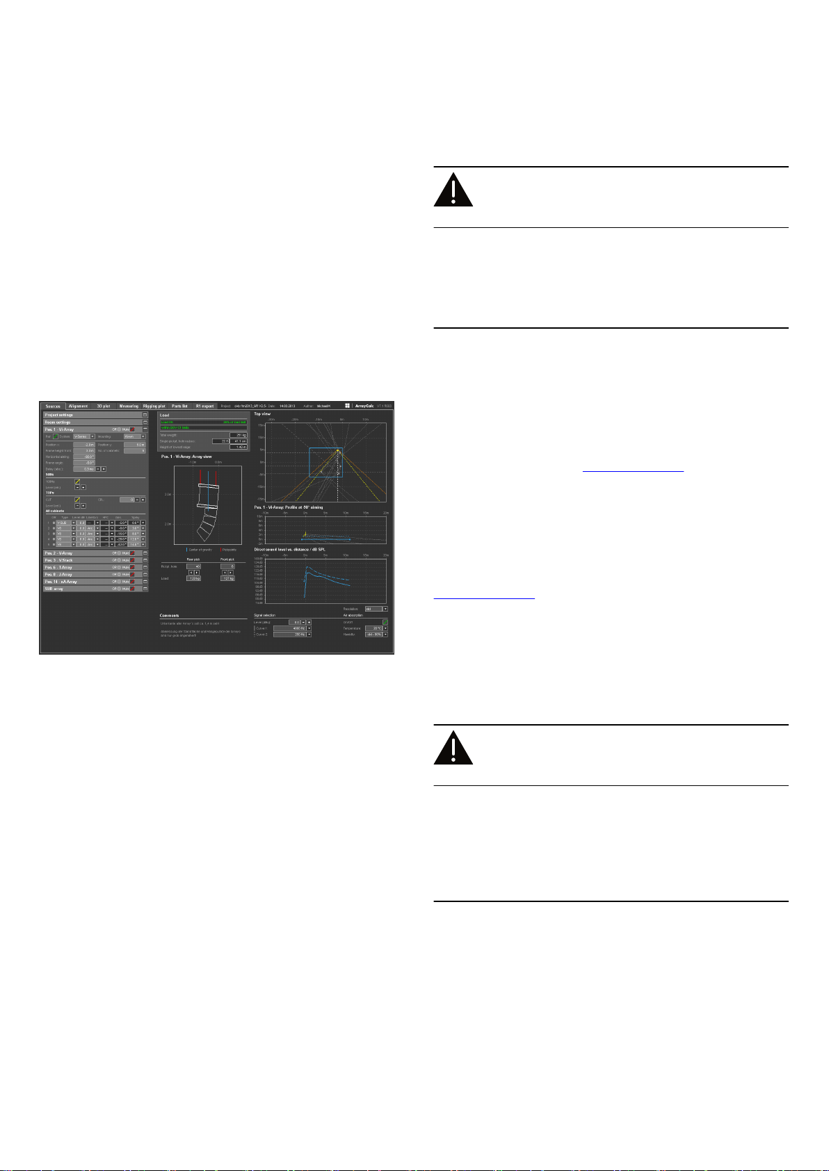
1.4. d&b ArrayCalc calculator software / TI 385
For both acoustic and safety reasons d&b line arrays must be
designed using the d&b ArrayCalc simulation tool. It is available as
a native stand-alone application for both Microsoft Windows (XP
or higher) and Mac OS X (10.4.10 or higher) operating systems
and can be downloaded at www.dbaudio.com.
The use of ArrayCalc is described in "TI 385 d&b Line array
design, ArrayCalc". This TI includes typical array configurations
within the permitted load limits. Carefully read this TI to become
familiar with the operation and behavior of ArrayCalc and in
particular with the mechanical load conditions and limitations.
d&b ArrayCalc
The TI can be downloaded from the d&b website at
www.dbaudio.com.
1.5. Secondary safety
WARNING!
Potential risk of personal injury and/or
damage to material!
The secondary safety suspension must be independent of the
primary suspension points and capable of carrying the total system
weight.
The additional safety device must be mounted in a way that the
array is caught by the safety device without any drop and swing in
the event that the primary suspension fails.
d&b Vi Rigging manual (1.2 EN) 5
Page 6

1.6. Operational safety
The assembly should always be carried out by two persons.
During assembly pay attention to the possible risk of crushing.
Wear suitable protective clothing.
Observe all instructions given on the respective instruction labels of
the rigging components and loudspeaker cabinets.
When chain hoists are in operation ensure that there is nobody
directly underneath or in the vicinity of the load.
Do not under any circumstances climb on the array.
d&b Vi Rigging manual (1.2 EN)6
Page 7
2. Rigging concept and components
2.1. Mounting and flying frames
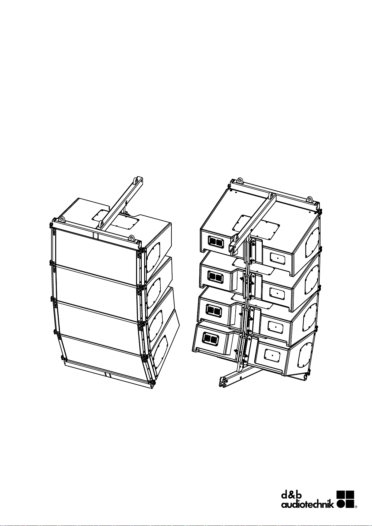
The d&b Vi loudspeakers are supplemented by two mounting
frames, the Z5387.xxx Vi Mounting frames, one for the top and
one for the bottom of an array.
These frames allows the setup of the following array
configurations:
d&b Vi Rigging manual (1.2 EN) 7
Page 8
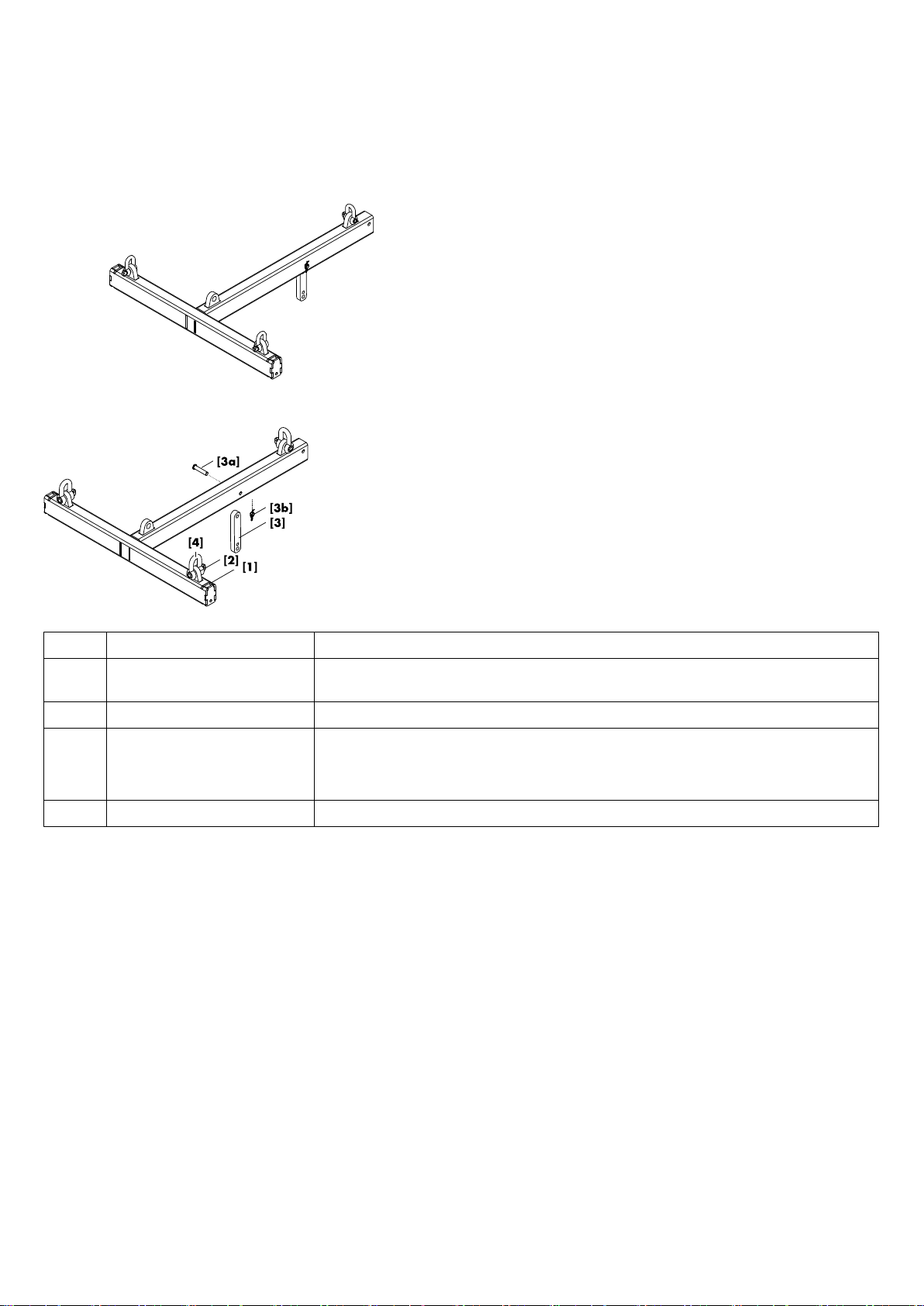
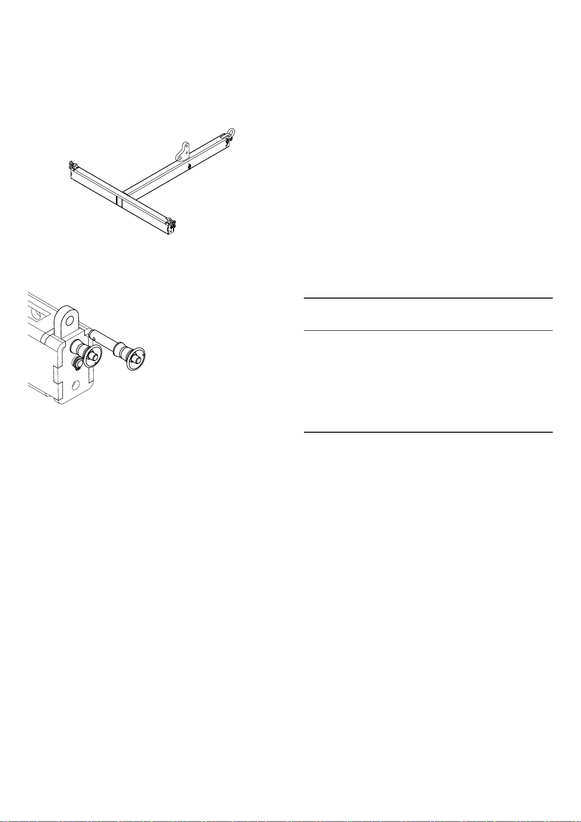
2.1.1. Z5387.000 Vi Mounting frame top
Intended use
The Z5387.000 Vi Mounting frame top is designed to support
arrays with a maximum weight of up to 136 kg (300 lb), which
corresponds to flown configurations of 4 x Vi-TOP or 2 x Vi-SUB
cabinets.
Scope of supply
Please verify the shipment for completeness and proper condition
of the items.
The Z5387.000 Vi Mounting frame top is equipped and supplied
with the following rigging components.
Note: In delivered condition, the Rear/Splay links [3A/B]
are not attached to the frame. For assembly instructions please
refer to Þ Chapter 2.4. "Rear/Splay links of the frames"
Þ Attaching the Splay/Rear links and the O-ring on page
15.
Pos.
Component Description
[1] Z5387.000
Weight (including all rigging components): 11.1 kg (24.5 lb).
Vi Mounting frame top
[2] Fixing points The Mounting frame is equipped with four fixing points for suspension using shackles.
[3] Rear link Rear link including Fixing bolt [3a] and Ring cotter [3b].
In connection with the Front links of the Vi loudspeaker cabinets, the Rear link of the frame is
used to attach the frame to the first cabinet of an array.
[4] 2t Shackle Three 2t shackle are provided for hoisting purposes.
d&b Vi Rigging manual (1.2 EN)8
Page 9
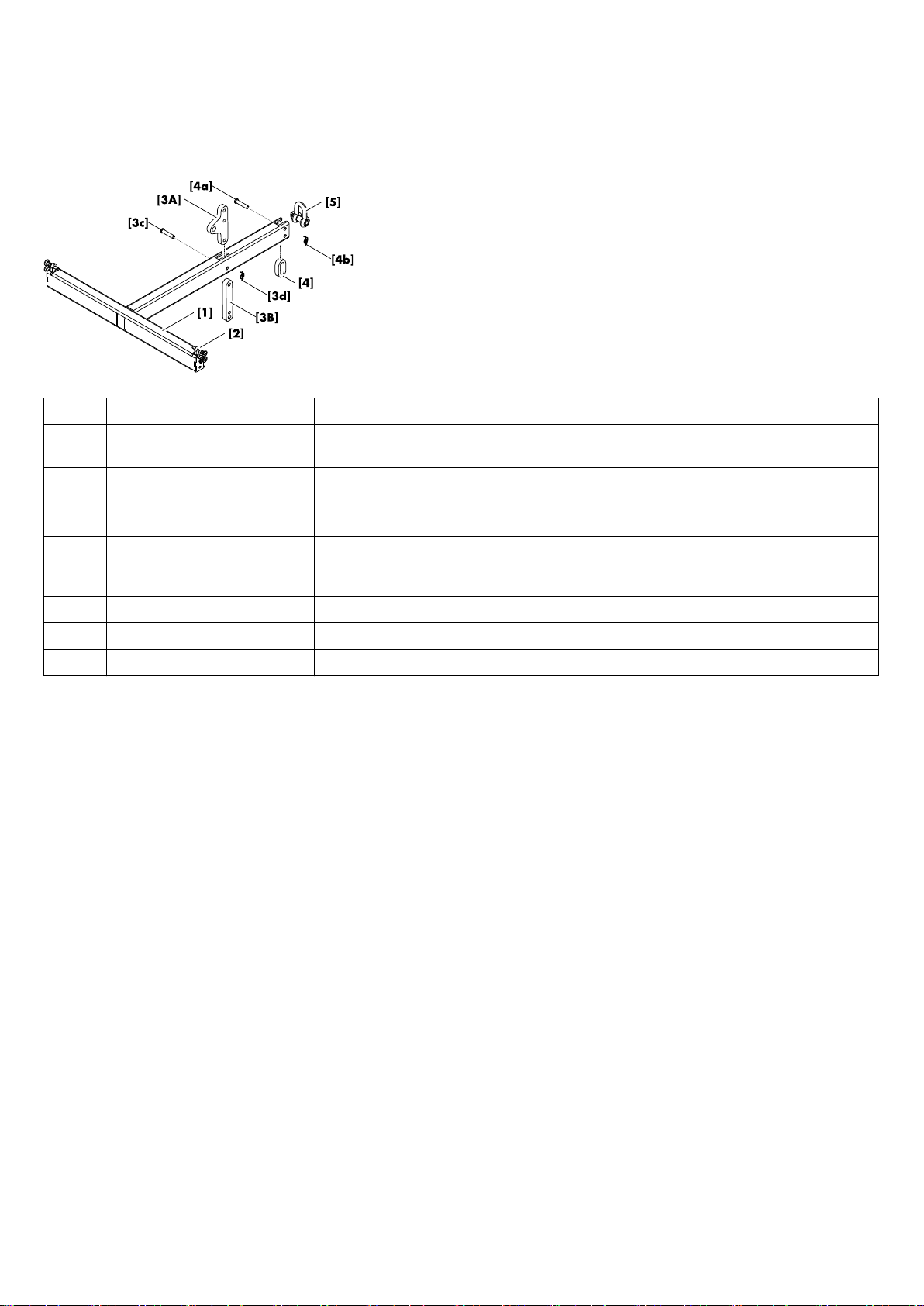
2.1.2. Z5387.001 Vi Mounting frame bottom
Intended use
The Z5387.001 Vi Mounting frame bottom is designed as a
pullback device to fix and/or pull back an array with either the
Z5387.000 Vi Mounting frame top or the Z5380 V Flying frame
mounted on top of the array.
Alternatively, the frame can be used as an adapter frame to be
attached underneath SUB cabinets in mixed array configurations
with the Z5380 V Flying frame mounted on top of the array. This
allows a maximum of up to 4 x Vi-TOP cabinets to be attached
underneath SUB cabinets.
Note: A detailed description of the Z5380 V Flying frame
including the relevant assembly instructions is given in the VSeries Rigging manual, which is supplied with the V Flying
frame.
NOTICE!
Construction notes
Each side of the tie bar at the front end of the frame is equipped
with a Front link. Both Front links are undetachably attached to the
tie bar using a fixing bolt. Directly above each of these fixing bolts
there is a Locking pin that serves to additionally stabilize the Front
link in its recess. For safety reasons, this Locking pin must always
be inserted and locked.
In addition, there is a second Locking pin on each side of the tie
bar which is used to connect the frame with a cabinet.
d&b Vi Rigging manual (1.2 EN) 9
Page 10
Scope of supply
Please verify the shipment for completeness and proper condition
of the items.
The Z5387.001 Vi Mounting frame bottom is equipped and
supplied with the following rigging components.
Note: In delivered condition, the Rear link [3] and the O-ring
[4] are not attached to the frame. For assembly instructions
please refer to Þ Chapter 2.4. "Rear/Splay links of the
frames" Þ Attaching the Splay/Rear links and the O-ring on
page 15.
Pos. Component Description
[1] Z5387.001
Weight (including all rigging components): 9.5 kg (21 lb).
Vi Mounting frame bottom
[2] Front links The Mounting frame is equipped with two Front links including the corresponding Locking pins.
[3A] Rear link In connection with the Front links, this rear link is used to attach the frame underneath the last
cabinet of an array.
[3B] Splay link (0°) In connection with the Front links, this additional splay link is used to attach the first TOP
cabinet at 0° underneath SUB cabinets in a mixed array configuration with SUB cabinets at
the top of the array.
[3c/d] Fixing bolt [3c] and Ring cotter [3d].
[4] O-ring Including Fixing bolt [4a] and Ring cotter [4b].
[5] 2t Shackle Additional 2t shackle.
d&b Vi Rigging manual (1.2 EN)10
Page 11
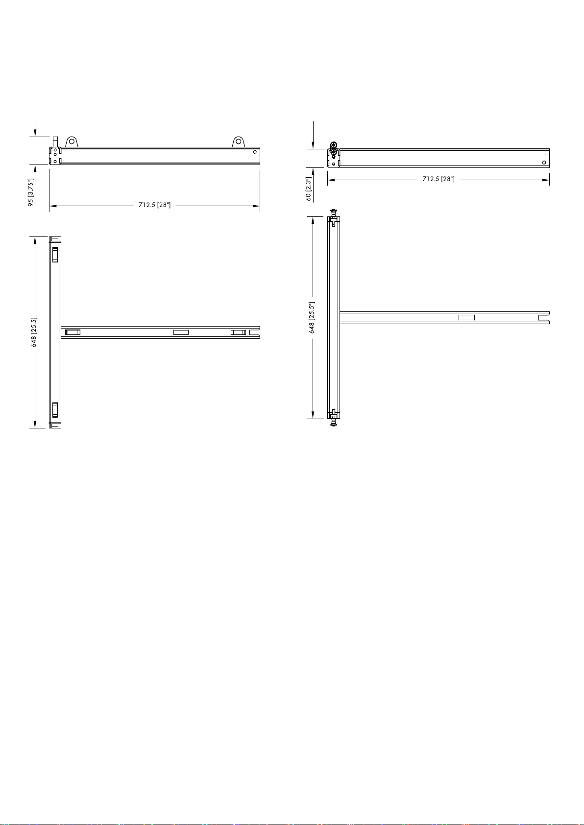
2.1.3. Dimensional drawings
Fig. 1: Z5387.000 Vi Mounting frame top,
dimensions in mm [inch]
Fig. 2: Z5387.001 Vi Mounting frame bottom,
dimensions in mm [inch]
d&b Vi Rigging manual (1.2 EN) 11
Page 12
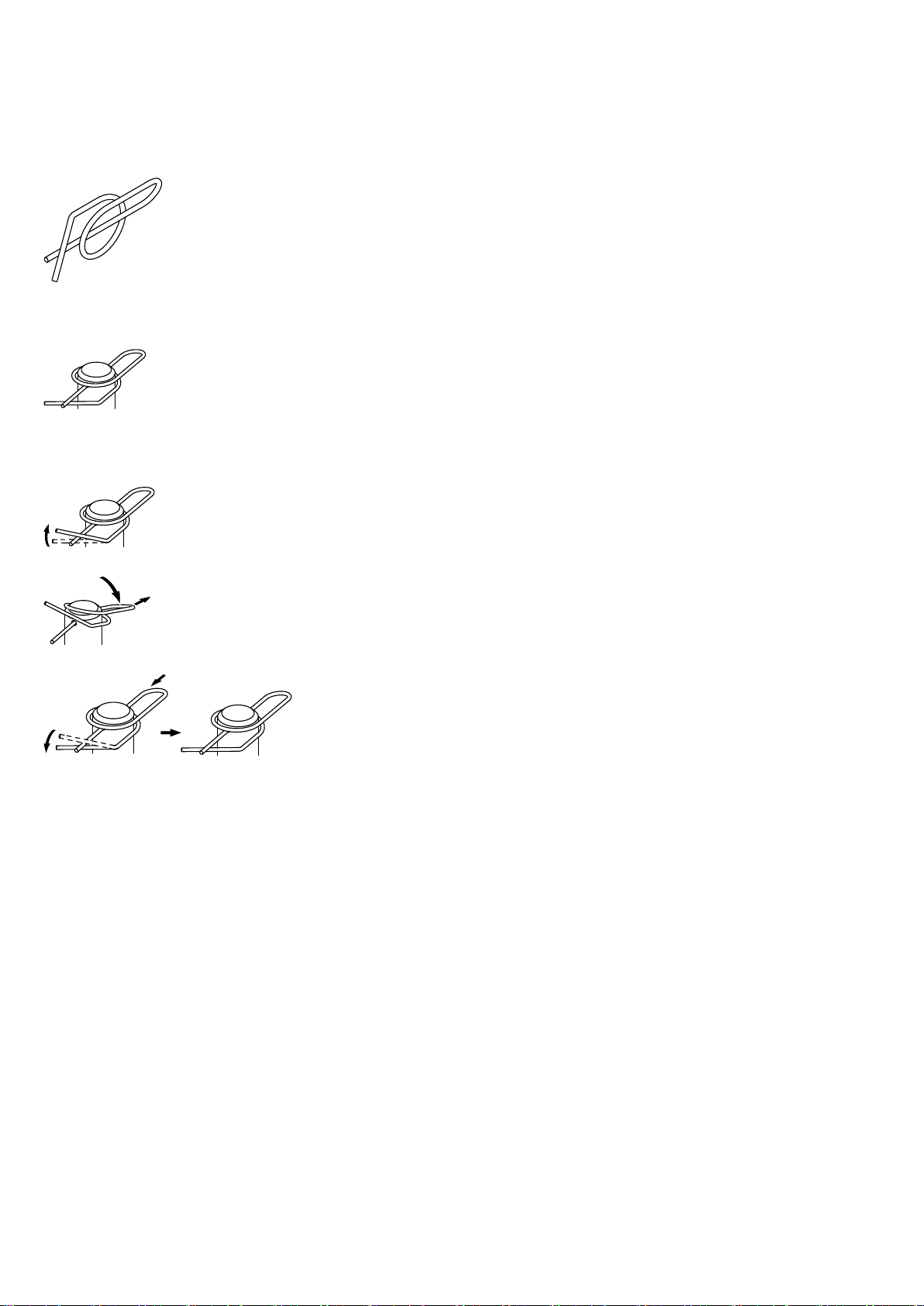
Fig. 3: Ring cotter
Ring cotter locked
2.2. Ring cotters
In connection with the Vi rigging system, ring cotters are used for
the following items to prevent the respective item from slackening
and/or loosening:
– Fixing bolt of the TOP and SUB cabinet's Rear links.
– Fixing bolt of the frame's Rear links and cable picks.
Function of the ring cotter
By default, the ring cotters are "locked" to prevent them from
loosening.
For modification reasons such as altering the position of the frame's
Splay link or exchanging a shackle, it may be necessary to
temporarily remove the cotter and reattach it afterwards.
For this purpose proceed as follows:
1. Unlock
Unlock the ring cotter by pushing up the front wire loop over
the straight wire shaft.
2. Release and remove
Push down the rear wire loop until the ring cotter snaps over
the edge of the bolt and remove the ring cotter.
3. Refit and lock
Refit the ring cotter by pushing the straight wire shaft through
the hole and pressing the front wire loop underneath the
straight wire shaft.
d&b Vi Rigging manual (1.2 EN)12
Page 13

2.3. Locking pins
WARNING!
Potential risk of personal injury and/or
damage to material!
The steel wires between the Locking pins of the cabinets and
rigging components are not intended to carry any load. The
cabinet's weight must only be carried by the Front and Splay/Rear
links in conjunction with the front and rear rigging strands of the
loudspeaker cabinets and the Mounting/Flying frames.
Ensure all Locking pins are fully inserted and securely locked
before lifting any load.
The Vi loudspeaker cabinets are equipped with two types of
Locking pins:
Fig. 4: Locking pin assembly
Shown with pin type [C]
Type [B]
Locking pin 9 x 40 mm.
Used for the cabinet's Splay/Rear links.
Type [C] Locking pin 8 x 23 mm.
Used for the Front links of the loudspeaker cabinets
and the Z5387.001 Vi Mounting frame bottom.
Note: The Locking pins are undetachably attached to the
different rigging components on the cabinet and the frames
using steel wires.
Throughout this manual these steel wires are not shown in the
corresponding illustrations.
Assembly
The quick lock mechanism applies to all types of Locking pins listed
above. To attach the Locking pin proceed as follows:
1. Press the button to release the locking mechanism ( [r]).
2. Insert the Locking pin through the respective link or socket until
it is fixed in place.
3. Release the button to lock the pin ( [l]).
4. Recheck the Locking pin is securely locked by briefly pulling
the Locking pin towards you.
To release and remove the Locking pins, proceed in
Þ
reverse order.
d&b Vi Rigging manual (1.2 EN) 13
Page 14

2.4. Rear/Splay links of the frames
WARNING!
Potential risk of personal injury and/or
damage to material!
The fixing bolt [B] is a safety-relevant item.
It is essential that the bolt is fitted correctly and secured by a
locked ring cotter [C].
Splay/Rear link positions
The position of the frame's Rear link depends on the type of cabinet
(Vi8/Vi12 or Vi-SUB) that is to be attached to the corresponding
Mounting frame.
In connection with the bottom frame, observe the direction of
attachment as shown below in Fig. 7 and Fig. 8.
Fig. 5: Splay link of the Z5387.000 Vi Mounting frame top
TOP position
Fig. 7: Rear link of the Z5387.001 Vi Mounting frame bottom
TOP position
Fig. 6: Splay link of the Z5387.000 Vi Mounting frame top
SUB position
Fig. 8: Rear link of the Z5387.001 Vi Mounting frame bottom
SUB position
d&b Vi Rigging manual (1.2 EN)14
Page 15

Attaching the Splay/Rear links and the O-ring
The assembly of both the Rear links and the O-ring is carried out in
the following manner:
1. Attach the corresponding item to its dedicated position.
Note: In connection with the bottom frame's Rear link,
observe the direction of attachment as shown in the previous
section Þ "Splay/Rear link positions" on page 14, following
Fig. 7 and Fig. 8.
2. Insert the Fixing bolt.
3. Insert and lock the Ring cotter.
Changing the Splay/Rear link position on Vi Mounting
frames
To change the Rear link position, follow the previous assembly
instructions in reverse order. The procedure for the top frame is
described as an example. The same procedure applies to the
bottom frame.
However, in connection with the bottom frame's Rear link, observe
the direction of attachment as shown in the previous section Þ
"Splay/Rear link positions" on page 14, following Fig. 5 and
Fig. 6.
1. Unlock and remove the ring cotter of the fixing bolt.
2. Pull out the fixing bolt and remove the Rear link.
3. Attach the Rear link to its new position and insert the fixing
bolt.
4. Secure the fixing bolt using the ring cotter and ensure the ring
cotter is properly locked.
d&b Vi Rigging manual (1.2 EN) 15
Page 16

2.5. Cabinet's rigging mechanism
Vi cabinets are mechanically connected to the Mounting/Flying
frame and subsequent loudspeakers using the Front links attached
to both sides of the cabinet front and the central Splay/Rear link at
the rear of the cabinet.
All necessary rigging components are mounted to the cabinet and
slide out when needed.
In principle, the Front and Splay/Rear link mechanism applies to
both the Vi8/Vi12 and Vi-SUB cabinets.
2.5.1. Front link mechanism
Vi8/Vi12 cabinets
1. Release both Locking pins and slide out the Front link.
2. Insert and lock one Locking pin to fix the link in place.
Fig. 9: Front link mechanism of Vi8/Vi12 cabinets
Fig. 10: Front link mechanism of Vi-SUB cabinets
Vi-SUB cabinets
The Front link mechanism of the Vi-SUB cabinets provides four
different settings:
a. SUB to Frame (Þ Fig. 11)
b. SUB to SUB with 0° splay between the cabinets (Þ Fig. 12).
c. SUB to SUB with 2.5° splay (free Þ Fig. 13) between the
cabinets.
d. SUB to SUB with 2.5° splay (blocked Þ Fig. 14) between the
cabinets.
This setting is used to prevent the cabinets from folding up.
Fig. 11: SUB to Frame
Fig. 12: SUB to SUB, 0° splay
Fig. 13: SUB to SUB, 2.5°
splay, free
Fig. 14: SUB to SUB, 2.5°
splay, blocked
d&b Vi Rigging manual (1.2 EN)16
Page 17

Fig. 15: Splay/Rear link mechanism
2.5.2. Splay/Rear link mechanism
Release the respective Locking pin(s) and fold out the Splay/Rear
link.
2.5.3. Setting splay angles for Vi-TOP cabinets
NOTICE!
The rigging system is designed as an intrinsically safe system. For
this reason, the second Locking pin (Safety pin [S]) must always be
inserted.
The splay angles between adjacent cabinets can be set in the
range from 0° to 14° in 1° steps. The splay angles are set at the
central rear rigging strands of the cabinets.
Fig. 16: Set splay angle (e.g. 0°)
Vi8/Vi12 cabinets
The Splay link of the Vi-TOP cabinets is designed as a straight link
with two holes.
The inner hole defines the splay angle while the outer elongated
hole is used for the second Locking pin (Safety pin [S]) as shown
in the graphic opposite.
d&b Vi Rigging manual (1.2 EN) 17
Page 18

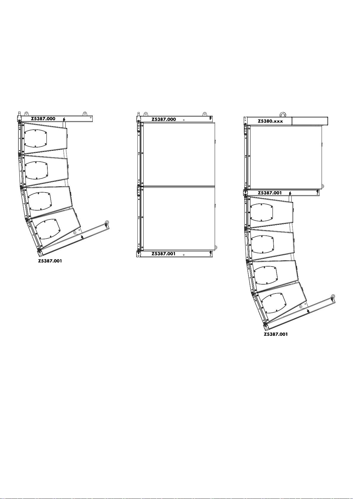
3. Arrays and assembly
Fig. 17: Vi8/Vi12 array 4-deep
For assembly instructions, please refer to:
Þ Chapter 3.2. "Vi8/Vi12 Array" on page 19
Fig. 18: Vi-SUB column 2-deep
For assembly instructions, please refer to:
Þ Chapter 3.3. "Vi-SUB Column" on page 22
Fig. 19: Mixed array
For assembly instructions, please refer to:
Þ Chapter 3.4. "Mixed array" on page 25
d&b Vi Rigging manual (1.2 EN)18
Page 19

3.1. Setup preparation
Check the acoustical and mechanical setup using ArrayCalc and
prepare enough printouts for each array.
The plan enables the riggers to set up the suspension points, the
securing points and the chain hoists.
When on site first:
– Clear the working areas and ensure there is enough space to
set up and lift the array.
– Check that the hoists are exactly in the specified position.
– Ensure the chains are not twisted.
Inspections before setup
Before setup carry out a visual inspection of all system components
for faults. This also includes the loudspeaker and in particular the
rigging parts of the cabinets (Front and Splay/Rear links).
Damaged components must be withdrawn from use immediately.
Please follow the instructions given in Þ Chapter 6. "Care and
maintenance / Disposal" on page 35.
3.2. Vi8/Vi12 Array
Remarks and limitations
In combination with the Z5387.000 Vi Mounting frame top, a
maximum of 4 x Vi-TOP cabinets can be flown.
To fly more than 4 x Vi-TOP cabinets, the Z5380 V Flying frame
must be used.
In this case, please follow the assembly instructions given in the VSeries Rigging manual, which is supplied with the V Flying frame.
In the manual, refer to "Flown array, section V8/V12 Array".
Preparations
For this type of setup the Rear link of the mounting frame must be
attached to the TOP position. Check the position and alter it if
necessary as described in Þ Chapter 2. "Rigging concept and
components", Þ 2.4. "Rear/Splay links of the frames" .
Note: Observe the direction of attachment as shown in the
graphic opposite.
1. Prepare the first cabinet
Prepare the Front and Splay links of the first cabinet as described
in Þ Chapter 2. "Rigging concept and components",
Þ "Cabinet's rigging mechanism" .
d&b Vi Rigging manual (1.2 EN) 19
Page 20

[0°]
[7°]
2. Attach the Mounting frame to the first cabinet
1. Lower the frame onto the cabinet until ...
– the Front links fit into the slots at the front of the frame.
– the Rear link of the frame fits into the rear rigging strand of
the cabinet.
2. Insert and lock the second Locking pins of the cabinet's Front
links on both sides.
3. At the rear, align the inner hole of the Rear link with the [0°]
hole of the rear rigging strand.
4. Insert the first Locking pin to the [0°] hole.
5. Insert the second Locking pin (Safety pin).
3. Add further cabinets
1. Prepare the Front and Splay links of the next cabinet as
described in Þ Chapter 2. "Rigging concept and
components", Þ "Cabinet's rigging mechanism" .
2. Lift the assembly to a suitable working height.
3. Attach the prepared cabinet to the corresponding slots on the
front of the upper cabinet.
4. Insert and lock the second Locking pins of the cabinet's Front
links on both sides.
5. Raise the bottom cabinet until the Splay link of the upper
cabinet fits into the rear rigging strand of the bottom cabinet.
6. Align the inner hole of the Splay link with the appropriate hole
for the desired splay angle (e.g. [7°]).
7. Insert the first Locking pin to fix the angle and cabinet in place.
8. Insert the second Locking pin (Safety pin).
To add further cabinets, proceed in the same manner until the
assembly is completed.
d&b Vi Rigging manual (1.2 EN)20
Page 21

4. Attach the bottom frame
The Z5387.001 Vi Mounting frame bottom is used if the
application requires the array to have an overall vertical angle that
is not covered by ArrayCalc or cannot be obtained by the
intended suspension.
The bottom frame allows the attachment of additional steel wire
ropes or hoists.
Note: For this application, please also observe the safety and
assembly instructions given in Þ Chapter 5. "Hoisting and
aiming the array" Þ 5.2. "Modifying the vertical aiming of
the array" on page 33.
To attach the bottom frame, proceed as follows:
4a. Remove the Splay link
To enable the attachment of the frame, the Splay link of the lowest
TOP cabinet must be removed.
1. Unlock and remove the ring cotter of the fixing bolt.
2. Pull out the fixing bolt and take out the Splay link.
Note: Keep the fixing bolt and ring cotter aside. The items
are required to fix the Rear link of the frame to the rear rigging
strand of the cabinet.
4b. Prepare the bottom frame
The Rear link of the bottom frame must be attached to the TOP
position. Check the position and alter it if necessary as described in
Þ Chapter 2. "Rigging concept and components", Þ 2.4. "Rear/
Splay links of the frames" .
Note: Observe the direction of attachment as shown in the
graphic opposite.
4c. Attach the bottom frame for pullback purposes
1. Lift the assembly to a suitable working height.
2. Release the upper Locking pins of the frame's Front links on
both sides.
3. Place the frame underneath the cabinet so that...:
– the Front links fit into the slots at the front of the cabinet.
– the Rear link of the frame fits into the rear rigging strand of
the cabinet.
4. Insert and lock the upper Locking pins of the frame's Front links
on both sides.
d&b Vi Rigging manual (1.2 EN) 21
Page 22

5. At the rear, align the Rear link with the hole of the TOP
cabinet's Splay link.
6. Reinsert the fixing bolt.
7. Insert and lock the ring cotter.
5. Check the assembly
Before hoisting the array to its operating position, recheck the
actual status of the entire assembly according to the checklist given
in Þ Chapter 4. "Safety and system checks" on page 32.
3.3. Vi-SUB Column
Remarks and limitations
In connection with the Z5387.000 Vi Mounting frame top, a
maximum of 2 x Vi-SUB cabinets can be flown.
For more than 2 x Vi-SUB cabinets, the Z5380 V Flying frame must
be used.
In this case, please follow the assembly instructions given in the VSeries Rigging manual which is supplied with the V Flying frame. In
the manual refer to "Flown array", section "V-SUB Column".
Preparations
For this type of setup the Rear link of the mounting frame must be
attached to the SUB position. Check the position and alter it if
necessary as described in Þ Chapter 2. "Rigging concept and
components", Þ 2.4. "Rear/Splay links of the frames" .
Note: Observe the direction of attachment as shown in the
graphic opposite.
1. Prepare the first cabinet
1. Prepare the Front links of the first cabinet as described in
Þ Chapter 2. "Rigging concept and components",
Þ "Cabinet's rigging mechanism" .
2. At the rear top, release both Locking pins.
d&b Vi Rigging manual (1.2 EN)22
Page 23

2. Attach the Mounting frame to the first cabinet
1. Lower the frame onto the cabinet until the Front links fit into the
slots at the front of the frame.
2. Insert the second Locking pins of the cabinet's Front links on
both sides.
3. At the rear of the cabinet, align the frame's Rear link with the
appropriate hole on the rear rigging strand of the cabinet.
4. Reinsert both Locking pins.
3. Add second/further cabinet(s)
1. Prepare the Front links of the next cabinet as described in
Þ Chapter 2. "Rigging concept and components",
Þ "Cabinet's rigging mechanism" on page 16.
2. Lift the current assembly to a suitable working height.
3. Position the next cabinet below the assembly.
4. Lower the assembly onto the cabinet until the Front links of the
bottom cabinet fit into the slots of the upper cabinet.
5. Insert the second Locking pins of the cabinet's Front links on
both sides.
6. On the rear rigging strand, release the Locking pins of both
cabinets.
7. Fold out the Rear link of the upper cabinet.
8. Reinsert the Locking pin on the upper cabinet.
9. Fold the Rear link into the rigging strand of the bottom cabinet.
10. Reinsert the two Locking pins on the bottom cabinet.
d&b Vi Rigging manual (1.2 EN) 23
Page 24

4. Attach the bottom frame for pullback purposes
The Z5387.001 Vi Mounting frame bottom is used if the
application requires the array to have an overall vertical angle that
is not covered by ArrayCalc or cannot be obtained by the
intended suspension.
The bottom frame allows the attachment of additional steel wire
ropes or hoists.
Note: For this application, please also observe the safety and
assembly instructions given in Þ Chapter 5. "Hoisting and
aiming the array" Þ 5.2. "Modifying the vertical aiming of
the array" on page 33.
To attach the bottom frame, proceed as follows:
4a. Remove the Rear link
To enable the attachment of the frame, the Rear link of the lowest
SUB cabinet must be removed.
1. Unlock and remove the ring cotter of the fixing bolt.
2. Pull out the fixing bolt and take out the Splay link.
Note: Keep the fixing bolt and the ring cotter aside. The items
are required to fix the Rear link of the frame to the rear rigging
strand of the cabinet.
4b. Prepare the bottom frame
The Rear link of the bottom frame must be attached to the SUB
position. Check the position and alter it if necessary as described in
Þ Chapter 2. "Rigging concept and components", Þ 2.4. "Rear/
Splay links of the frames" .
Note: Observe the direction of attachment as shown in the
graphic opposite.
4c. Attach the bottom frame
1. Lift the assembly to a suitable working height.
2. Release the upper Locking pins of the frame's Front links on
both sides.
3. Place the frame underneath the cabinet so that...:
– the Front links fit into the slots at the front of the cabinet.
– the Rear link of the frame fits into the rear rigging strand of
the cabinet.
4. Insert and lock the upper Locking pins of the frame's Front links
on both sides.
d&b Vi Rigging manual (1.2 EN)24
Page 25

5. At the rear, align the Rear link with the hole of the SUB
cabinet's Splay link.
6. Reinsert the Locking pin
7. Reinsert the fixing bolt.
8. Insert and lock the ring cotter.
5. Check the assembly
Before hoisting the array to its operating position, recheck the
actual status of the entire assembly according to the checklist given
in Þ Chapter 4. "Safety and system checks" on page 32.
3.4. Mixed array
NOTICE!
If SUB cabinets are included in the array, these must always be
positioned at the top of the column.
Remarks and limitations
For a mixed setup, two frames are required. One frame is used for
suspension and the second frame acts as an adapter to add Vi8/
Vi12 cabinets below the Vi-SUB cabinets.
NOTICE!
In mixed arrays, the Z5380 V Flying frame must always be used as
a suspension device.
For the second frame, there are two options depending on the
number of TOP cabinets to be mounted:
– Up to 4 x Vi-TOP cabinets can be mounted underneath the
SUB cabinets using the Z5387.001 Vi Mounting frame bottom
in addition to the V Flying frame.
– If the array includes more than 4 x Vi-TOP cabinets, an
additional Z5380 V Flying frame must be used instead of the
Vi Mounting frame bottom.
In this case, please follow the assembly instructions given in
the V-Series Rigging manual which is supplied with the V Flying
frame. In the manual refer to "Flown array", section "Mixed
array".
As a first step to building this type of setup, the Z5380 V Flying
frame must be attached at the top of the array. This is done in the
following way:
d&b Vi Rigging manual (1.2 EN) 25
Page 26

1. Prepare the flying frame
For a mixed type of setup, the Splay link of the V Flying frame must
be attached to «POSITION V-SUB». Check the position and alter it
if necessary. Proceed as follows:
Changing the Splay link position
WARNING!
Potential risk of personal injury and/or
damage to material!
The fixing bolt [B] of the frame's Splay link bears the full load of
the array.
It is essential that the bolt is fitted correctly and secured by a
locked ring cotter [C].
To change the Splay link position, proceed as follows:
1. Release and remove the Locking pin of the Splay link at park
position and fold out the Splay link.
2. Unlock and remove the ring cotter of the fixing bolt.
3. Pull out the fixing bolt and remove the Splay link.
d&b Vi Rigging manual (1.2 EN)26
Page 27

4. Attach the Splay link to its new position and insert the fixing
bolt.
5. Secure the fixing bolt using the ring cotter and ensure the ring
cotter is properly locked.
2. Prepare the first SUB cabinet
1. Prepare the Front links of the first cabinet as described in
Þ Chapter 2. "Rigging concept and components",
Þ "Cabinet's rigging mechanism" .
2. At the rear top, release both Locking pins.
3. Attach the Flying frame to the first SUB cabinet
1. Lower the frame onto the cabinet until the Front links fit into the
slots at the front of the frame.
2. Insert the second Locking pins of the cabinet's Front links on
both sides.
3. On the rear rigging strand of the cabinet, release both Locking
pins.
4. Fold the Splay link into the rigging strand and reinsert the
Locking pins.
d&b Vi Rigging manual (1.2 EN) 27
Page 28

4. Add further SUB cabinet(s)
If you want to add further SUB cabinets, proceed as follows:
1. Prepare the Front links of the next cabinet as described in
Þ Chapter 2. "Rigging concept and components",
Þ "Cabinet's rigging mechanism" on page 16.
2. Lift the current assembly to a suitable working height.
3. Position the next cabinet below the assembly.
4. Lower the assembly onto the cabinet until the Front links of the
bottom cabinet fit into the slots of the upper cabinet.
5. Insert the second Locking pins of the cabinet's Front links on
both sides.
6. On the rear rigging strand, release the Locking pins of both
cabinets.
7. Fold out the Rear link of the upper cabinet.
8. Reinsert the Locking pin on the upper cabinet.
9. Fold the Rear link into the rigging strand of the bottom cabinet.
10. Reinsert the two Locking pins on the bottom cabinet.
5. Attach the Vi Mounting frame bottom
The Rear link of the bottom frame must be attached to the SUB
position. Check the position and alter it if necessary as described in
Þ Chapter 2. "Rigging concept and components", Þ 2.4. "Rear/
Splay links of the frames" .
Note: Observe the direction of attachment as shown in the
graphic opposite.
5a. Remove the Rear link of the (lowest) SUB cabinet
To enable the attachment of the frame, the Rear link of the lowest
SUB cabinet must be removed.
1. Unlock and remove the ring cotter of the fixing bolt.
2. Pull out the fixing bolt and take out the Splay link.
Note: Keep the fixing bolt and the ring cotter aside. The items
are required to fix the Rear link of the frame on the rear
rigging strand of the cabinet.
d&b Vi Rigging manual (1.2 EN)28
Page 29

5b. Attach the bottom frame
1. Lift the assembly to a suitable working height.
2. Release the upper Locking pins of the frame's Front links on
both sides.
3. Place the frame underneath the cabinet so that...:
– the Front links fit into the slots at the front of the cabinet.
– the Rear link of the frame fits into the rear rigging strand of
the cabinet.
4. Insert and lock the upper Locking pins of the frame's Front links
on both sides.
5. At the rear, align the Rear link with the hole of the SUB
cabinet's Splay link.
6. Reinsert the Locking pin
7. Reinsert the fixing bolt.
8. Insert and lock the ring cotter.
6. Add Vi8/Vi12 cabinets below the SUB cabinet(s)
Adding Vi8/Vi12 cabinets below the SUBs is a similar procedure
to setting up a flown Vi8/Vi12 array as described in Þ Chapter
3.2. "Vi8/Vi12 Array" on page 19.
However, to attach the first TOP cabinet underneath the frame, use
the additional Splay link of the frame ("Z5387.001 - Pos. 3B").
Þ
Attach the Splay link to the frame correspondingly.
To add futher TOP cabinets, proceed in the same manner as
described in Þ Chapter 3.2. "Vi8/Vi12 Array" on page 19.
d&b Vi Rigging manual (1.2 EN) 29
Page 30

7. Attach a further bottom frame for pullback
purposes
The Z5387.001 Vi Mounting frame bottom is used if the
application requires the array to have an overall vertical angle that
is not covered by ArrayCalc or cannot be obtained by the
intended suspension.
The bottom frame allows the attachment of additional steel wire
ropes or hoists.
Note: For this application, please also observe the safety and
assembly instructions given in Þ Chapter 5. "Hoisting and
aiming the array" Þ 5.2. "Modifying the vertical aiming of
the array" on page 33.
To attach the bottom frame, proceed as follows:
7a. Remove the Splay link
To enable the attachment of the frame, the Splay link of the lowest
TOP cabinet must be removed.
1. Unlock and remove the ring cotter of the fixing bolt.
2. Pull out the fixing bolt and take out the Splay link.
Note: Keep the fixing bolt and the ring cotter aside. The items
are required to fix the Rear link of the frame to the rear rigging
strand of the cabinet.
7b. Prepare the bottom frame
The Rear link of the bottom frame must be attached to the TOP
position. Check the position and alter it if necessary as described in
Þ Chapter 2. "Rigging concept and components", Þ 2.4. "Rear/
Splay links of the frames" .
Note: Observe the direction of attachment as shown in the
graphic opposite.
7c. Attach the bottom frame
1. Lift the assembly to a suitable working height.
2. Release the upper Locking pins of the frame's Front links on
both sides.
3. Place the frame underneath the cabinet so that...:
– the Front links fit into the slots at the front of the cabinet.
– the Rear link of the frame fits into the rear rigging strand of
the cabinet.
4. Insert and lock the upper Locking pins of the frame's Front links
on both sides.
d&b Vi Rigging manual (1.2 EN)30
Page 31

5. At the rear, align the Rear link with the hole of the TOP
cabinet's Splay link.
6. Reinsert the fixing bolt.
7. Insert and lock the ring cotter.
8. Check the assembly
Before hoisting the array to its operating position, recheck the
actual status of the entire assembly according to the checklist given
in Þ Chapter 4. "Safety and system checks" on page 32.
d&b Vi Rigging manual (1.2 EN) 31
Page 32

4. Safety and system checks
Before hoisting the array to its operating position, recheck the
actual status of the assembly as follows:
4.1. Mechanical setup
– Check the attachment of the Mounting/Flying frame(s) to the
cabinets:
– Ensure all Locking pins are properly inserted and locked.
– Ensure all Fixing bolts are properly fitted and secured by a
locked Ring cotter.
– Check the attachment of all Front links on both sides of the
cabinets and ensure all Locking pins are properly inserted and
locked.
– Check the splay angles and the attachment of the Splay/Rear
links on the rear of the cabinets:
– Ensure all Locking pins are properly inserted and locked.
– Ensure all Fixing bolts are properly fitted and secured by a
locked Ring cotter.
4.2. Wiring
– Check the wiring.
If the amplifiers are already wired and powered on, use their
System check functions or Channel mute switches and a test
signal to check the correct operation and routing of all
channels and cabinets.
d&b Vi Rigging manual (1.2 EN)32
Page 33

5. Hoisting and aiming the array
5.1. Hoisting the array
WARNING!
Potential risk of personal injury and/or
damage to material!
Always ensure that each of the hoists is able to carry the total
weight of the array.
When hoisting the array, unpredictable dynamic forces as well as
swinging of the array must be taken into account. This may lead to
personal injury and/or damage to the rigging components and
loudspeaker cabinets.
Ensure that there is nobody directly underneath or in the vicinity of
the load who is not involved in the setup.
When all the mechanical adjustments, system checks and safety
checks have been made, the array can be hoisted up to its
operating position and firmly attached to the onsite roof
construction.
The chain hoist motors must raise the system slowly and evenly so
that it does not swing or move from side to side during hoisting.
5.2. Modifying the vertical aiming of the array
The Z5387.001 Vi Mounting frame bottom is used if the
application requires the array to have an overall vertical angle that
is not covered by ArrayCalc or cannot be obtained by the
intended suspension.
The bottom frame allows the attachment of additional steel wire
ropes or hoists.
WARNING!
Potential risk of personal injury and material
damage!
Using additional wires or hoists changes the load conditions within
the array and its rigging components. The load calculated using
ArrayCalc no longer applies. For this reason, increasing the
vertical angle of an array requires individual considerations and
calculations based on the relevant onsite conditions.
Always pull the additional wires or hoists to the back and upwards,
as shown in the graphic opposite.
Fig. 20: Z5387.001 Vi Mounting frame bottom serving to increase
the overall vertical angle of the array
d&b Vi Rigging manual (1.2 EN) 33
Page 34

5.2.1. Dedicated fixing points
Fig. 21: Vi8/Vi12 array 4-deep
Fig. 23: Vi-SUB assembly
Fig. 22: Vi-SUB column 2-deep
Fig. 24: Vi8/Vi12 array 12-deep
d&b Vi Rigging manual (1.2 EN)34
Page 35

6. Care and maintenance / Disposal
6.1. Visual and functional inspection
WARNING!
Potential risk of personal injury and/or
damage to material
To eliminate the potential risk of accident due to malfunctioning of
a component, regularly inspect all system components.
Cabinet enclosure
– Visual inspection of all fitting plates for obvious damage (e.g.
cracks or corrosion).
– Visual inspection of the rear rigging strand for obvious
damage (e.g. cracks, deformation or corrosion) including all
drilled holes of the component.
– Inspection of all fitting plates including front grills to ensure
they are securely attached.
Front and Splay (Rear) links
Visual inspection regarding deformation and damage (e.g. cracks
and corrosion) including all drilled holes of the component.
Locking pins
Visual inspection for deformation, cracks and corrosion of the
component.
Flying and Mounting frames
Visual inspection regarding deformation and damage (e.g. cracks
and corrosion) including all drilled holes of the component.
6.2. Disposal
When out of use the rigging components must be disposed of in
accordance with the national environmental regulations.
Ensure that damaged rigging components are disposed of in a
way that they cannot be used again.
d&b Vi Rigging manual (1.2 EN) 35
Page 36

7. Manufacturer's declaration
We hereby declare that the equipment designated below is
designed and built in the version sold by us in such a way as to
comply with the relevant fundamental safety and health criteria of
the applicable EC Directive(s). This declaration shall cease to be
valid if alterations are made to the equipment without our prior
agreement.
d&b Loudspeaker cabinets
(With integrated rigging components.)
– Z0535, Vi8
– Z0536, Vi12
– Z0538, Vi-SUB
d&b Rigging components
(Including all additional components.)
– Z5387.000, Vi Mounting frame top
– Z5387.001, Vi Mounting frame bottom
– Z5380.901, V Flying frame SC
National standards and technical specifications
applied:
DIN EN ISO 12 100, DIN EN 1050, DIN EN 18 800-1,
BGV C1.
Backnang, 2013-07-23
Frank Bothe,
Head of R&D
d&b audiotechnik GmbH
d&b Vi Rigging manual (1.2 EN)36
Page 37

D2708.EN .01, 08/2013 © d&b audiotechnik GmbH
www.dbaudio.com
 Loading...