

Page 1

T-Series Rigging manual (1.1 EN)
Page 2
References in the manual
WARNING!
This refers to a potentially dangerous situation
which may lead to personal injury and/or
damage to the equipment and/or material.
CAUTION!
This refers to a potentially dangerous situation
which may lead to damage to the equipment or
material.
NOTICE: This refers to a situation which may lead to
damage to the equipment or material or
cause the equipment to malfunction.
Note: Additional information and/or references.
Symbols on the equipment
Please refer to the information in the
operating manual.
General Information
T-Series
Rigging manual
Version 1.1 EN, 02/2009, D2993.EN .01
Copyright © 2009 by d&b audiotechnik GmbH; all rights reserved.
Keep this manual with the product or in a safe place so that it is
available for future reference.
When reselling this product, hand over this manual to the new
customer.
If you supply d&b products, please draw the attention of your
customers to this manual. Enclose the relevant manuals with the systems.
If you require additional manuals for this purpose, you can order them
from d&b.
d&b audiotechnik GmbH
Eugen-Adolff-Strasse 134, D-71522 Backnang, Germany
Telephone +49-7191-9669-0, Fax +49-7191-95 00 00
E-mail: docadmin@dbaudio.com, Internet: www.dbaudio.com
Page 3

Contents
1. Safety precautions...........................................................4
1.1. Intended use...............................................................................................4
1.1.1. Load capacity/System safety.....................................................4
1.1.2. ArrayCalc / TI 385.......................................................................5
1.2. Operational safety....................................................................................5
2. T-Series rigging concept..................................................6
2.1. Z5370 T Flying frame..............................................................................6
2.1.1. System components overview...................................................7
2.1.2. Flying frame dimensions..............................................................8
2.2. T-Series Locking pins................................................................................9
2.3. T Load adapter........................................................................................10
2.4. T-Series cabinets.....................................................................................11
2.4.1. Altering the HF dispersion on T10 cabinets........................11
2.4.2. Functionality of the cabinet's rigging mechanism..............11
2.5. E7451/53 Touring cases......................................................................13
3. Preparing the setup.......................................................14
3.1. General.....................................................................................................14
3.2. Inspections................................................................................................14
3.3. Suspension of the Flying frame..........................................................15
3.3.1. Single pickpoint operation.......................................................15
3.3.2. Dual pickpoint operation..........................................................16
3.4. Secondary safety....................................................................................17
3.5. Horizontal aiming and securing.........................................................18
4. T-Series arrays and assembly......................................19
4.1. Flown arrays............................................................................................20
4.1.1. T10 Array.....................................................................................20
4.1.2. T-SUB Column.............................................................................23
4.1.3. T-SUB/T10 Array........................................................................25
4.1.4. Setup of the E7451 Touring case assembly.......................27
4.2. T-Series ground stacks..........................................................................32
4.2.1. T10 ground stack........................................................................32
4.2.2. T-SUB/T10 ground stack..........................................................34
4.2.3. T-SUB stacks.................................................................................37
5. Checklist for the assembly of T-Series arrays..............38
5.1. System and safety checks.....................................................................38
5.1.1. Flown arrays................................................................................38
5.1.2. Ground stacks..............................................................................38
5.1.3. Wiring............................................................................................38
5.2. Hoisting and securing the array.........................................................39
6. Wind loads.....................................................................40
7. Care and maintenance / Disposal................................41
7.1. Transport / Storing................................................................................41
7.2. Visual and functional inspection.........................................................41
7.3. Disposal.....................................................................................................41
EC Declaration of Conformity............................................42
T-Series Rigging manual (1.1 EN) Contents - 1
Page 4

1. Safety precautions
1.1. Intended use
The T-Series rigging components (Flying frame, Load adapter, Locking
pins) must only be used in conjunction with d&b T-Series loudspeakers
as described in this manual.
Installation and setup should only be carried out by qualified and
authorized personnel observing the valid national Rules for the
Prevention of Accidents (RPA).
It is the responsibility of the person installing the assembly to ensure that
the suspension/fixing points are suitable for the intended use.
1.1.1. Load capacity/System safety
The Z5370 T Flying frame is designed to suspend a total
system weight of 250 kg (550 lb) – SWL.
The rigging components allow arrays of up to 10 x T10 cabinets or a
total system weight of 110 kg (242 lb) to be flown in any vertical splay
angle configuration between the cabinets.
For this purpose the Flying frame must be freely suspended using
appropriate steel wires or hoisting chains or using the d&b Z5147 Rota
Clamp (single pickpoint operation). Any other type of suspension of the
Flying frame is not allowed.
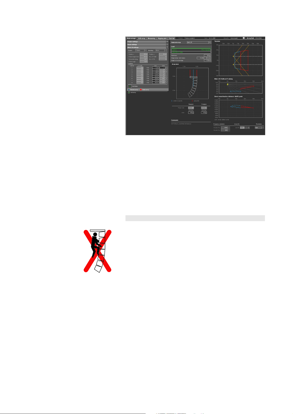
For arrays with a total system weight of more than 110 kg (242 lb) the
load conditions within the array have to be checked using the d&b
ArrayCalc calculator, which can be downloaded at
www.dbaudio.com.
T-Series Rigging manual (1.1 EN) Safety precautions - 1/Page 4 of 44
Page 5
1.1.2. ArrayCalc / TI 385
The use of ArrayCalc is described in "TI 385 J, Q and T-Series system
design, d&b ArrayCalc" which is also supplied with the Z5370 T Flying
frame.
This TI includes typical array configurations within the permitted load
limits.
Carefully read this TI to become familiar with the operation and
behaviour of ArrayCalc and in particular with the mechanical load
conditions and limitations.
We also recommend you to attend the regularly hosted d&b T-Series
training seminars. Further information regarding the d&b seminars can
be requested directly from d&b audiotechnik sales partners.
1.2. Operational safety
During assembly pay attention to the possible risk of crushing. Wear
suitable protective clothing.
Observe all instructions given on the rigging components (Flying frame,
Load adapter) and the loudspeaker cabinets.
When chain hoists are in operation ensure that there is nobody directly
underneath or in the vicinity of the load.
Do not under any circumstances climb on the array.
T-Series Rigging manual (1.1 EN) Page 5 of 44
Page 6
2. T-Series rigging concept
T-Series cabinets are mechanically connected to the T Flying frame and
subsequent loudspeakers using the Front links attached to both sides of
the cabinet front and the central Splay link at the rear of the cabinet.
All necessary rigging components are mounted to the cabinet and slide
out when needed.
The T-SUB cabinets can also be attached to the T Flying frame either at
the top of an array with subsequent T10 loudspeakers attached or as a
column of T-SUBs.
2.1. Z5370 T Flying frame
The Z5370 T Flying frame is equipped and supplied with the following
rigging components:
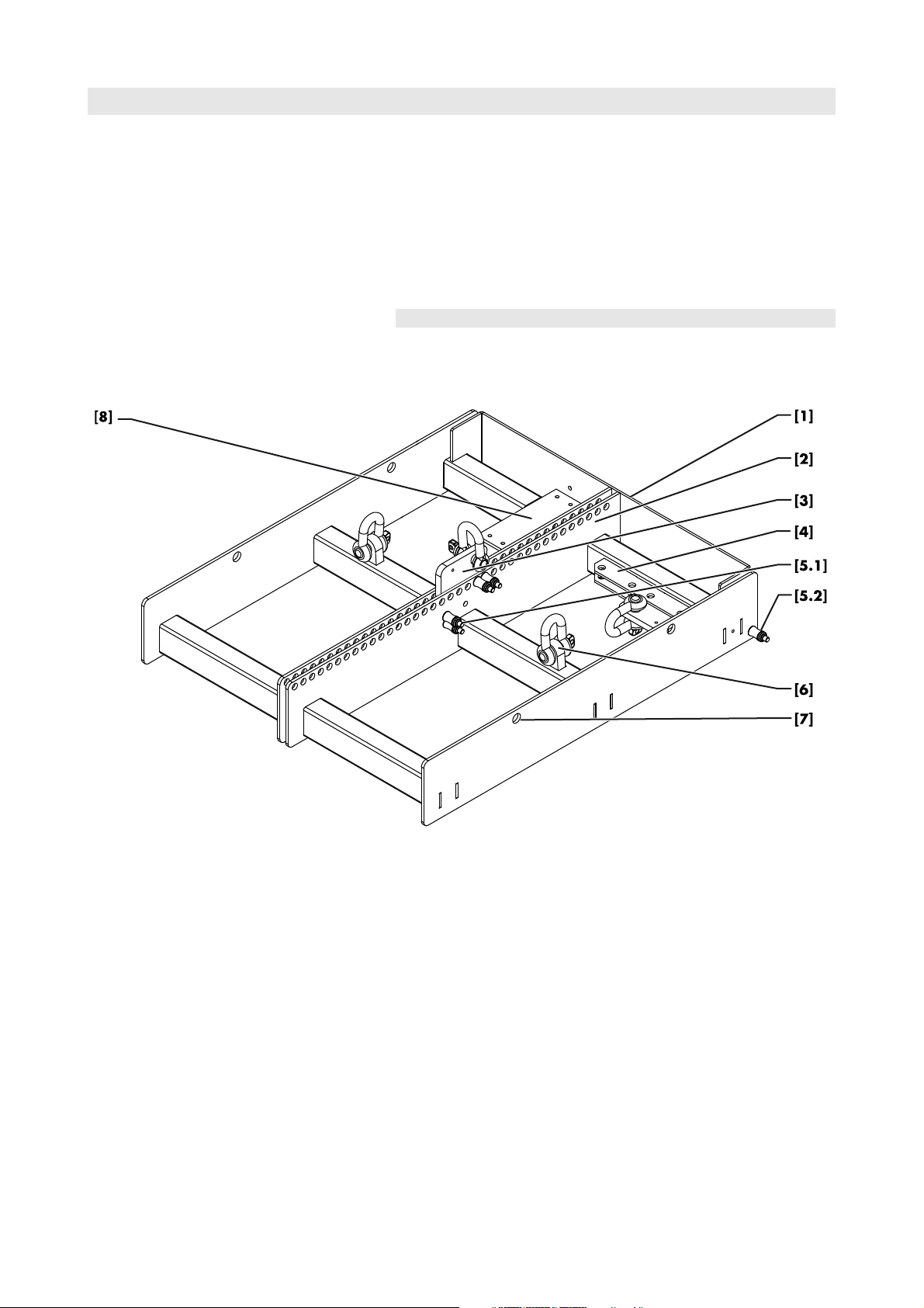
Fig. 1: Z5370 T Flying frame (rear view)
T-Series Rigging manual (1.1 EN) Page 6 of 44
Page 7
2.1.1. System components overview
T Flying frame
SWL: 250 kg (550 lb)
Z537000000001
Z055000000001
Pos. Component Description
Z5370 T Flying frame
[1]
The Z5370 T Flying frame is designed to support arrays consisting of
the following T-Series loudspeakers:
Code Type Weight incl. rigging comp.
Z0550 T10 11 kg (24 lb)
Z0560 T-SUB 17 kg (37 lb)
[2]
[3]
[4]
[5.1]
[5.2]
[6]
[7]
[8]
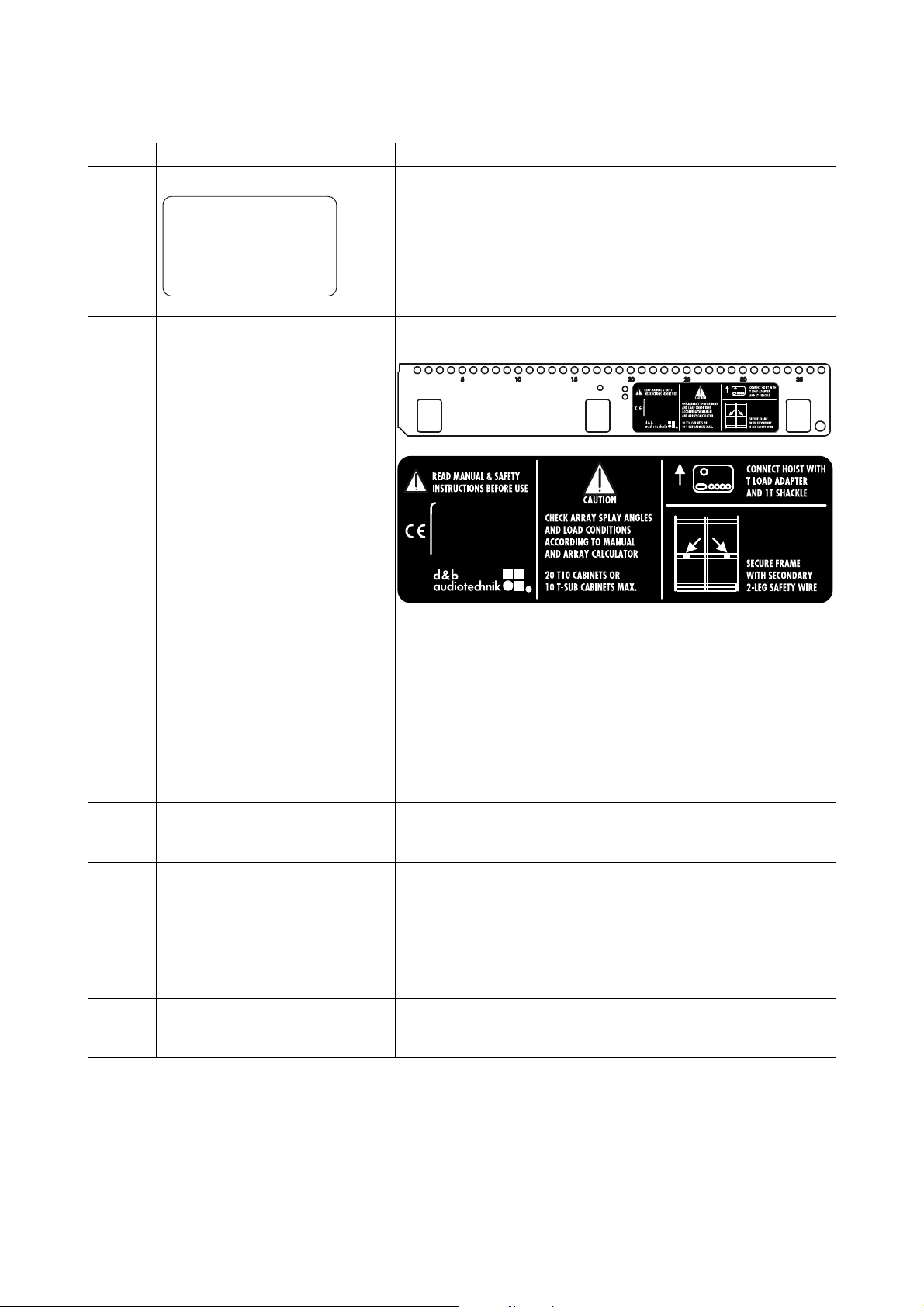
Center bar Center bar of the Flying frame with hole index and user instruction
T Load adapter
Park position
Locking pins Splay link
Locking pins Front links
Safety point(s) The Flying frame is supplied with two safety points. Each safety point is
Additional holes Two additional holes 12.5 mm each are provided in the side bars of the
Mounting plate The Flying frame is equipped with an additional mounting plate
The weight of the Flying frame including all rigging components is 12 kg
(26.5 lb).
label.
The main hole index at the top of the center bar provides a total of 37
holes numbered with an increment of five. Using the T Load adapters
the Flying frame can be suspended from one or two pick points (please
refer to section 3.3.1 Single pickpoint operation on page 15 and
section 3.3.2 Dual pickpoint operation on page 16).
The Flying frame is supplied with two Load adapters. Each Load
adapter is equipped with a 1 t shackle to allow single or dual pickpoint
operation (please refer to section 2.3 T Load adapter on page 10).
During transport the Load adapters should be stored in their park
position [4].
Four Locking pins are provided with the Flying frame and are used to
connect T-Series cabinets to the frame (please refer to section 2.2 TSeries Locking pins on page 9).
equipped with a 1 t shackle to attach a secondary safety device (please
refer to section 3.4 Secondary safety on page 17).
frame. These can be used for horizontal aiming and securing the array
against rotation (please refer to section 3.5 Horizontal aiming and
securing on page 18).
providing four M4 threaded inserts to accept inclinometers such as the
Teqsas LAP-TEQ line array positioning tool.
T-Series Rigging manual (1.1 EN) Page 7 of 44
Page 8
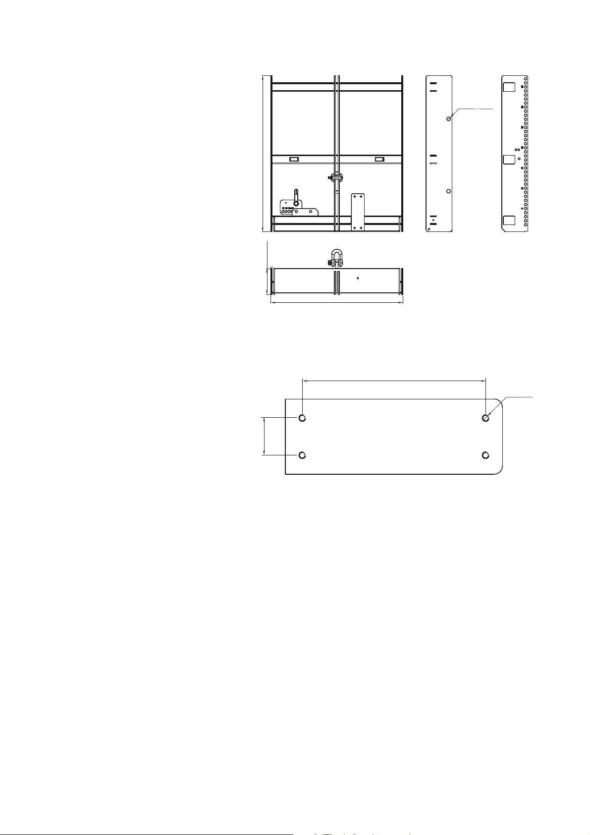
2.1.2. Flying frame dimensions
12.5 [0.5"]
540 [21.3"]
90 [3.5"]
456.5 [18"]
108.5 [4.3"]
4 x M4
22 [0.9"]
Fig. 2: Z5370 T Flying frame dimension in mm [inch]
Dimensions of the inclinometer mounting plate
Fig. 3: Dimension of the mounting plate in mm [inch]
T-Series Rigging manual (1.1 EN) Page 8 of 44
Page 9
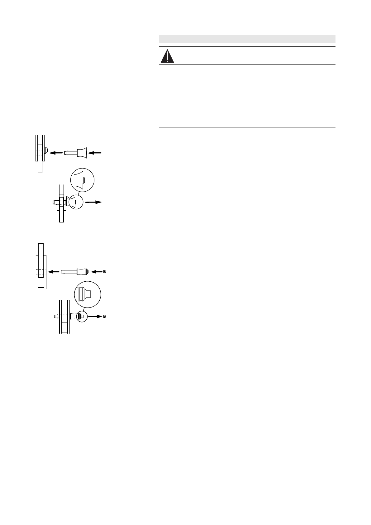
B
B
Fig. 4: Locking pins
for the cabinet's Front links.
2.2. T-Series Locking pins
WARNING!
The steel wires between the locking pins and the cabinets and
rigging components are not intended to carry any load.
The cabinet's weight must only be carried by the Front and
Splay/Rear links in conjunction with the front and rear rigging
strands of the loudspeaker cabinets and the Flying frame.
- Ensure all Locking pins are fully inserted and securely locked
before lifting any load.
The T-Series cabinets are equipped with the following Locking pins:
- Two Locking pins 5 mm for the cabinet Front links.
- Two (T10) resp. three (T-SUB) Locking pins 6 mm for the Splay/Rear
link on the central rear rigging strand.
The T Flying frame is equipped with the following Locking pins:
- Two Locking pins 6 mm [5.1] on the center bar of the frame to
connect the Splay/Rear link of the first cabinet to the frame.
- One Locking pin 5 mm [5.2] on either side at the front of the frame
to connect the Front links of the first cabinet to the frame.
- The two Load adapters supplied with the Flying frame are equipped
with a pair of Locking pins 6 mm.
Fig. 5: Locking pins
for the cabinet's Splay/Rear links
the Flying frame and the Load adapters.
Assembly
The quick lock mechanism applies to all types of Locking pins listed
above. To attach the Locking pin proceed as follows:
1. Press the button [B] to release the locking mechanism.
2. Insert the Locking pin through the respective link or socket until it is
fixed in place.
3. Release the button to lock the pin.
4. Recheck the Locking pin is securely locked by briefly pulling the
Locking pin towards you.
To release and remove the Locking pins follow the steps 1 to 3 in
reversed order.
T-Series Rigging manual (1.1 EN) Page 9 of 44
Page 10
2.3. T Load adapter
20
20
WARNING!
- Before attaching the Load adapter check the 1 t shackle is
properly fitted to the Load adapter and secured against
loosening.
- Ensure the Load adapter is properly attached to the center
bar of the frame and both Locking pins are fully inserted
and locked securely before lifting the array.
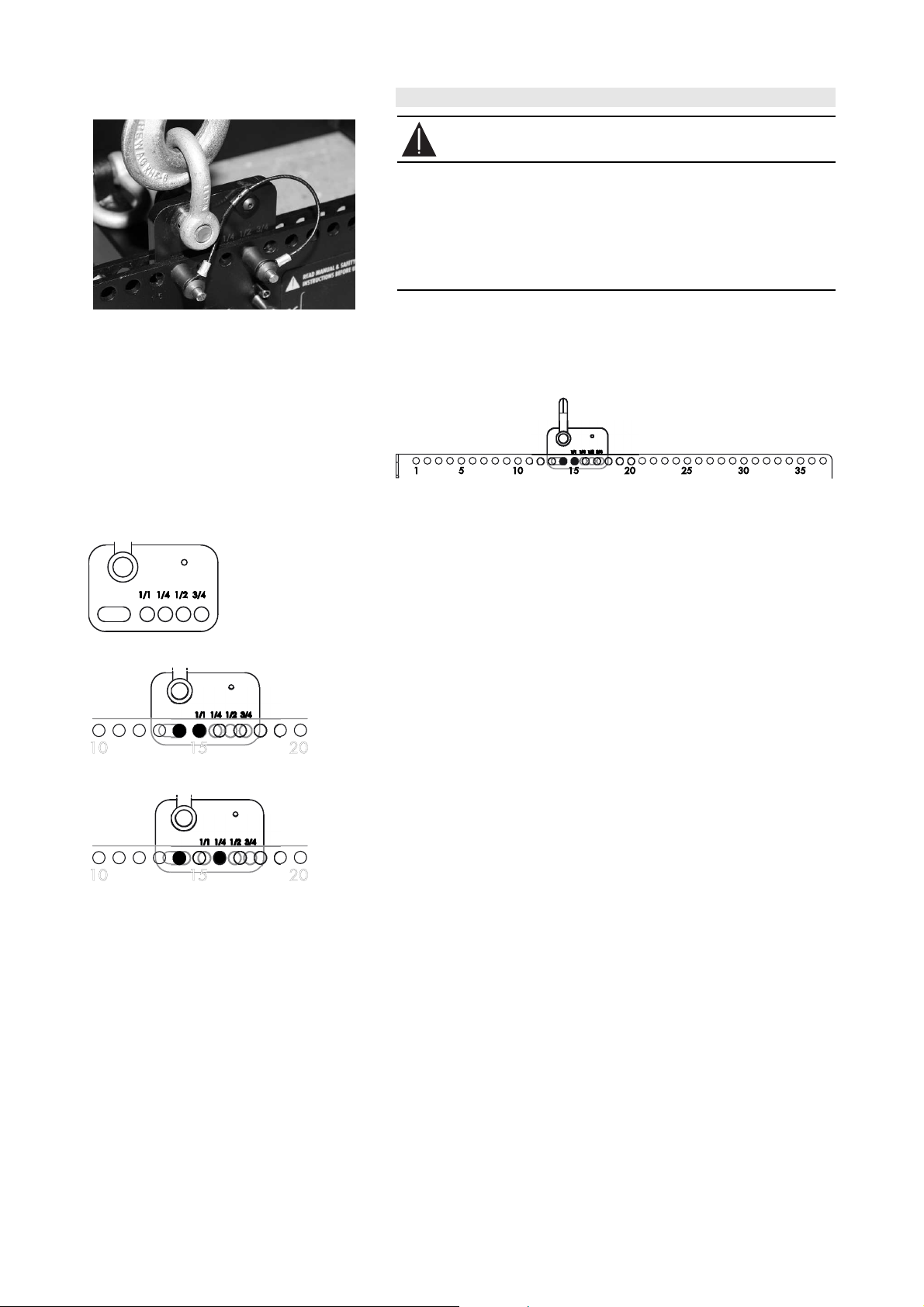
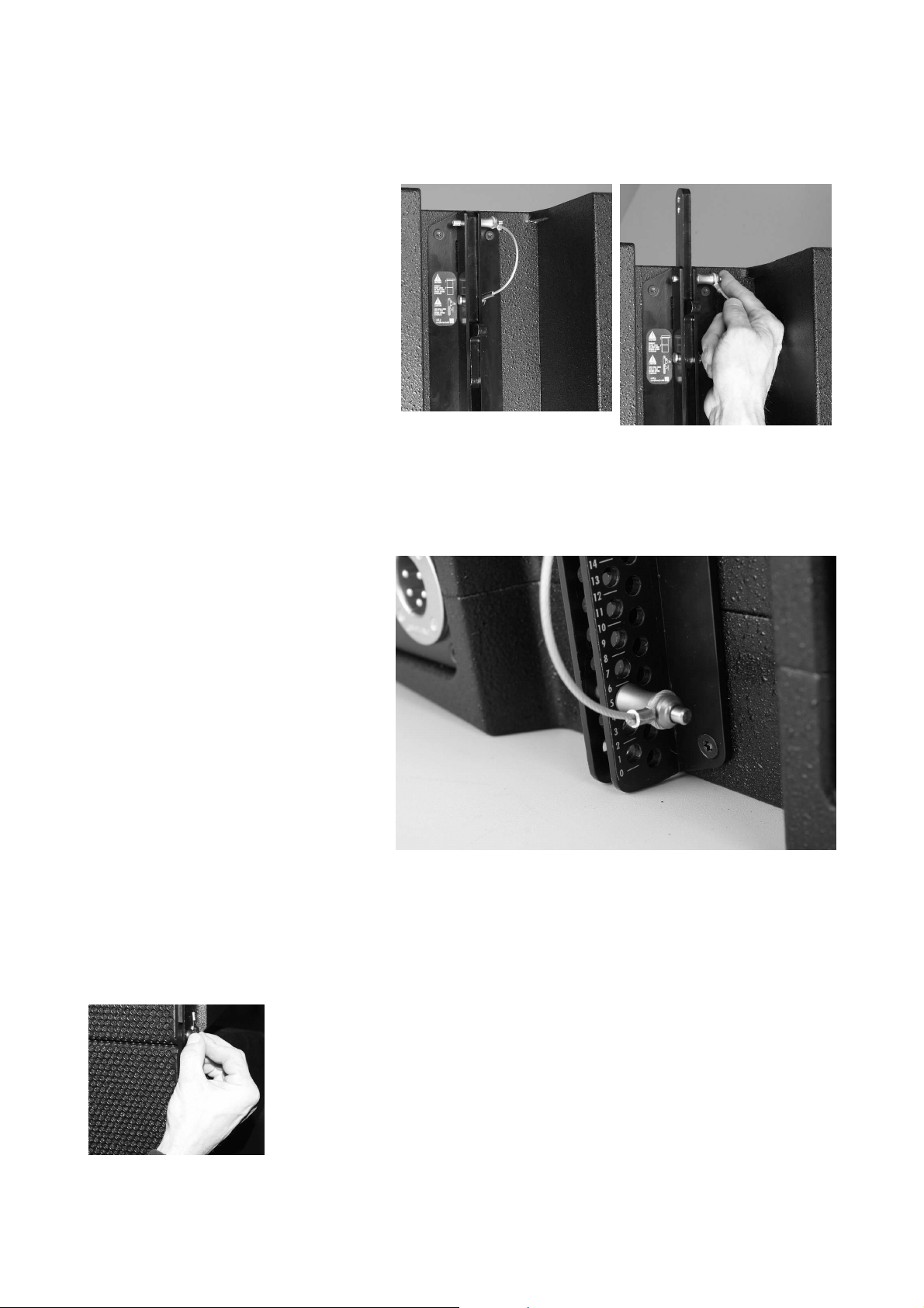
Fig. 6: T Load adapter
The Load adapter is attached to the center bar of the Flying frame
and fixed using its two Locking pins 6 mm.
In conjunction with the hole index of the center bar the Load adapter
provides a 1/4-hole resolution.
Fig. 7: T Flying frame hole index
Assembly
The Load adapter is equipped with four holes and one elongated hole.
The elongated hole always refers to the calculated main hole of the hole
index.
To attach the Load adapter proceed as follows:
Example:
Hole 14 has been calculated using ArrayCalc.
1. Attach the Load adapter to the center bar of the frame with the
elongated hole aligned to hole 14 of the hole index.
Fig. 8: Hole 14 (1/1)
Fig. 9: Hole 14 + 1/4
2. Insert and lock the first Locking pin to hole 14.
3. Move the Load adapter as long as the hole marked with 1/1 is in
line with the next hole of the hole index.
4. Insert and lock the second Locking pin.
To achieve other hole values (e.g. 14 + 1/4) align the Load adapter to
the desired hole value (1/4, 1/2 or 3/4 detents) and insert the second
Locking pin.
T-Series Rigging manual (1.1 EN) Page 10 of 44
Page 11
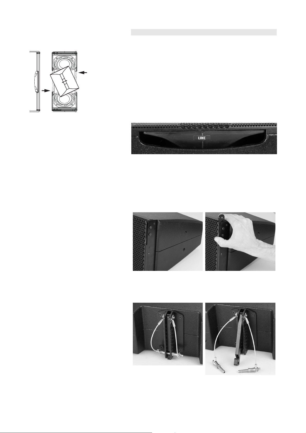
Fig. 10: Rotating the horn
(shown without front grill for better illustration)
2.4. T-Series cabinets
2.4.1. Altering the HF dispersion on T10 cabinets
When setting up T-Series arrays and ground stacks set the T10 cabinets
to line source mode.
Swapping between point and line source setups is performed by simply
rotating the horn by 90°. The horn is easily accessible from outside of
the cabinet and can be rotated without any tools or removal of the
front grill.
This is achieved through apertures on the cabinet sides by a mechanism
that provides detents at both the line and point source positions.
The line source mode is indicated by a label on the horn marked with
LINE as shown in the picture below.
2.4.2. Functionality of the cabinet's rigging mechanism
Front link mechanism
The Front link mechanism applies to both the T10 and the T-SUB
cabinets.
- Slide out the Front link until it is fixed in place.
Splay/Rear link mechanism
T10
- Release both Locking pins and fold out the Splay link.
T-Series Rigging manual (1.1 EN) Page 11 of 44
Page 12
T-SUB
- Release the Locking pin and slide out the Rear link up to its stop
position.
- Insert the Locking pin to fix the Rear link in place.
Preset splay angles on T10 cabinets
The splay angles between T10 cabinets can be set in the range from 0°
to 15° in 1° steps.
The splay angles are set at the central rear rigging strands of the T10
cabinets.
Interconnecting the cabinets
Both the T10 and T-SUB cabinets are interconnected with their Front
links on both sides of the cabinet's front and with the Splay/Rear links
on the center rigging strand at the cabinet's rear.
Front links
Once the Front links are fit into the respective track of the next cabinet,
the cabinets are interconnected by inserting the Locking pins to both
sides of the cabinet.
T-Series Rigging manual (1.1 EN) Page 12 of 44
Page 13
Splay / Rear links
T10
The Splay links of the T10 cabinets are fold out and hooked into the
preset Locking pin on the rear rigging strand of the next cabinet.
Once the Splay link is hooked in, the second Locking pin must be
inserted. The second Locking pin acts as a "safety pin" to secure the
Splay link from possible hooking off and to fix the set splay angle.
T-SUB
The Rear link of the T-SUB cabinets are fit into the rear rigging strand of
the next cabinet and fixed in position with the Locking pin of the Rear
link.
Once the Rear link is fit into the rear rigging strand of the next cabinet
the Rear link is fixed in place using the two Locking pins of the next
cabinet.
2.5. E7451/53 Touring cases
E7451 Touring case 4 x T10 assembly
The E7451 Touring case is intended to store and transport 4 x T10
cabinets which are interconnected by their Front links. It also allows you
to connect the assembly to the Flying frame or below T-SUBs within a
mixed T-SUB/T10 array in one procedure.
The assembly instructions are given in section 4.1.4 Setup of the E7451
Touring case assembly starting from page 27.
E7453 Touring case 2 x T-SUB assembly
The E7453 Touring case is intended to store and transport 2 x T-SUB
cabinets. If the two T-SUB cabinets are interconnected by their Front
and Rear links it also allows you to connect the assembly to the Flying
frame in one procedure to build T-SUB columns or mixed T-SUB/T10
arrays.
The assembly follows the instructions given in section 4.1.2 T-SUB
Column starting from page 23.
T-Series Rigging manual (1.1 EN) Page 13 of 44
Page 14

3. Preparing the setup
3.1. General
Check the acoustical and mechanical setup using the ArrayCalc array
calculator and prepare enough printouts for each array.
The plan enables the riggers to set up the suspension points, the
securing points and the chain hoists.
When on site first:
- clear the working areas,
- check that the hoists are exactly in the specified position,
- the chains are not twisted,
- there is enough space to set up and lift the array.
3.2. Inspections
Before setup carry out a visual inspection of all system components for
faults. This also includes the loudspeaker and in particular the rigging
parts of the cabinets (Front and Splay links).
Damaged components must be withdrawn from use immediately. Please
follow the instructions in section 7. Care and maintenance / Disposal on
page 41 of this manual.
T-Series Rigging manual (1.1 EN) Page 14 of 44
Page 15

3.3. Suspension of the Flying frame
WARNING!
The working load limits of the chain hoists and their suspension
points has to be high enough to carry the total system weight.
As during dual pickpoint operation the motors might not always
be synchronized each of the suspension points must be able to
carry the total system weight.
The Flying frame must be freely suspended using appropriate
steel wires or hoisting chains or using the d&b Z5147 Rota
Clamp (Single pickpoint operation). Any other type of
suspension of the Flying frame is not allowed.
The suspension of the Flying frame is carried out using one or two Load
adapter(s), depending on the chosen type of suspension (Single or Dual
pickpoint operation).
Fig. 11: ArrayCalc Hole position for
Single pickpoint operation
Fig. 12: Single pickpoint operation
Note:
The shown hoist connector chains in the graphics below
are not supplied with the T Flying frame
For this purpose the Z5155 Q Hoist connector chain can
be used. Its length of 52 cm (20.5“) allows enough space
for the hang of most 1 t motor chain containers.
3.3.1. Single pickpoint operation
In "Single pickpoint operation" the position of the Load adapter defines
the vertical aiming of the entire array.
The corresponding hole position is calculated using ArrayCalc (Fig. 11).
Attaching the Load adapter
1. Place the Flying frame on the ground with the hole index
facing upwards.
2. Choose the appropriate hole position in the center bar of the
frame according to the ArrayCalc calculation and attach the
Load adapter correspondingly.
3. Connect the hoist connector chain to the shackle of the Load
adapter.
Note:
Alternatively the d&b Z5147 Rota Clamp can be
attached the Load adapter to allow the
attachment of the Flying frame to overhead bars
or trusses with a tube diameter up to 51 mm (2").
Attaching the cable pick
In "Single pickpoint Operation" do not attach the cable pick to the
frame to not affect the total vertical aiming of the entire array by the
cable load.
Fig. 13: Cable pick
Single pickpoint operation
We recommend to attach the cable pick to the hook of the hoisting
motor.
T-Series Rigging manual (1.1 EN) Page 15 of 44
Page 16

Fig. 14: ArrayCalc Hole positions for
Dual pickpoint operation
Fig. 15: Dual pickpoint operation
Fig. 16: Cable pick
Dual pickpoint operation
3.3.2. Dual pickpoint operation
With "Dual pickpoint operation" the vertical aiming of the array is set
by trimming the hoist motors after the array has been fully assembled
and lifted to its operating position.
The corresponding hole positions are calculated using ArrayCalc (Fig.
14).
Attaching the Load adapter(s)
1. Place the Flying frame on the ground with the hole index
facing upwards.
2. Choose the appropriate hole positions for the Frontpick and
Rearpick in the center bar of the frame according to the
ArrayCalc calculation and attach the Load adapters
correspondingly.
3. Connect the hoist connector chain to the shackle of the Load
adapter.
Attaching the cable pick
We recommend to attach the cable pick to the hook of the hoisting
motor of the Rearpick.
T-Series Rigging manual (1.1 EN) Page 16 of 44
Page 17

3.4. Secondary safety
WARNING!
The secondary safety suspension must be independent of the
primary suspension points and capable of carrying the total
system weight.
- Attach the additional safety device in a way that the array is
caught by the safety device without any significant drop and
swing in the event that the primary suspension fails.
Secondary safety at the Flying frame
The Flying frame is equipped with two safety points [1.2] fitted with two
1 t shackles to accept a secondary safety device such as a 2-leg safety
wire or safety chains.
Note:
Assembly
Ensure the two 1 t shackles are properly fitted to the safety points of the
Flying frame.
2-leg safety wire
Safety chains
When using chains as secondary safety device ensure the chains are
not twisted and the hooks are in the right direction as shown in the
picture below.
The safety devices shown in the pictures below are not
part of the delivery.
T-Series Rigging manual (1.1 EN) Page 17 of 44
Page 18

Fig. 17: Additional fixing points of the
frame for horizontal aiming and
protection against rotation and swing
3.5. Horizontal aiming and securing
WARNING!
If the system is used in an open-air environment the influence of
wind has to be taken into account. The protection against
rotation and swing has to withstand higher forces. Refer to
section 6. Wind loads on page 40.
After the array has been lifted to its operating position the horizontal
aiming has to be set and the array should be secured against rotation
and swing.
The protection can be attached to the additional holes at the side bars
of the Flying frame - Fig. 17.
T-Series Rigging manual (1.1 EN) Page 18 of 44
Page 19

4. T-Series arrays and assembly
WARNING!
Due to the compact and lightweight T-Series cabinets and
rigging components the assembly may be carried out by a
single person.
However, during assembly or dismantling the array could
suddenly move or swing.
- Therefore carry out the setup with two persons with one
person securing the Array.
- Ensure no other person remains in the vicinity of the
assembly area.
T-Series loudspeakers and T Flying frames can be assembled in the
following ways.
T10 Array
(Refer to section 4.1.1
starting from page 20)
T-SUB column
(Refer to section 4.1.2
starting from page 23)
T-SUB/T10 Array
(Refer to section 4.1.3
starting from page 25)
T Ground stacks
(Refer to section 4.2
starting from page 32)
T-Series Rigging manual (1.1 EN) Page 19 of 44
Page 20

4.1. Flown arrays
4.1.1. T10 Array
Limitation
A maximum of 20 x T10 cabinets are allowed to be flown.
Preparations
- Prepare the flying cables and link cables according to the number of
amplifier channels and cabinets used.
- Ensure the HF sections of the T10 cabinets to be used are set to Line
source.
Order of assembly
1. Suspend the Flying frame
- Suspend the Flying frame according to the chosen type of suspension
as described in section 3.3 on page 15.
- Release the two Locking pins at the front of the frame.
2. Prepare the first T10 cabinet
- Prepare the Front and Splay links of the first T10 cabinet as
described in section 2.4 on page 11.
3. Attach the Flying frame to the first T10 cabinet
- Lower the frame onto the cabinet until the Front links fit into the slots
at the front of the frame.
- Insert and lock the frame's Locking pins through the Front links of the
T10 cabinet on both sides.
- Release the upper Locking pin at the support point for the Splay link
on the center bar of the frame.
- Fold up the Splay link of the cabinet into the track of the frame's
center bar until the link hooks over the Locking pin.
To achieve this you may first have to lower the frame slightly more.
- Lift the frame by hand until the Splay link hooks into the Locking pin
and keep holding the frame in this position.
- Insert the second Locking pin (safety pin) to secure the Splay link.
- Lift the frame to a suitable working height to add the next cabinet.
T-Series Rigging manual (1.1 EN) Page 20 of 44
Page 21

4. Add further T10 cabinets
- Preselect the desired splay angle on the upper cabinet.
- Slide and fold out the Front and Splay links of the next cabinet.
- On the rear hook the Splay link of the next cabinet over the preset
Locking pin of the upper cabinet.
- Lower the cabinet to enable the second Locking pin to be inserted.
- Insert the second Locking pin (safety pin) to secure the Splay link of
the cabinet.
- Release the Locking pins at the front of the upper T10 cabinet.
- Raise the bottom cabinet.
- Align the cabinets so as to enable the Locking pins to be inserted
through the Front links of the bottom cabinet.
- Insert and lock the Locking pins on both sides.
- To add further cabinets proceed in the same manner until the
assembly is completed.
T-Series Rigging manual (1.1 EN) Page 21 of 44
Page 22

5. Rig the cabling
- Connect the flying cables and link cables according to the number of
amplifier channels and cabinets used.
- Attach the cable pick depending on the chosen type of suspension
(Single or Dual pickpoint operation setup) as described in section 3.3
Suspension of the Flying frame on page 15.
6. Check the assembly
- Before hoisting the array to its operating position recheck the actual
status of the assembly according to the checklist given in section 5.
Checklist for the assembly of T-Series arrays on page 38.
7. Derig the array
- To lower the array and dismantle it, follow the assembly instructions
in reverse order. The same safety instructions apply.
T-Series Rigging manual (1.1 EN) Page 22 of 44
Page 23

4.1.2. T-SUB Column
Limitation
A maximum of 10 x T-SUB cabinets are allowed to be flown as a SUB
column.
Preparations
Prepare the flying cables and link cables according to the number of
amplifier channels and cabinets used.
Order of assembly
1. Suspend the Flying frame
- Suspend the Flying frame according to the chosen type of suspension
as described in section 3.3 on page 15.
- Release the two Locking pins at the front of the frame.
2. Prepare the first T-SUB cabinet
- Prepare the Front links of the first T-SUB cabinet as described in
section 2.4 on page11.
3. Attach the Flying frame to the first T-SUB cabinet
- Lower the frame onto the cabinet until the Front links fit into the slots
at the front of the frame.
- Insert and lock the frame's Locking pins on both sides.
- Release the two Locking pins at the support point for the Rear link on
the track of the frame's center bar.
- Release the Locking pin of the Rear link of the T-SUB cabinet.
- Slide out the Rear link up to its stop position into the track of the
frame's center bar.
- Insert the Locking pin of the Rear link at the T-SUB cabinet.
- Insert the two Locking pins at the support point for the Rear link on
the track of the frame's center bar.
T-Series Rigging manual (1.1 EN) Page 23 of 44
Page 24

4. Add the next T-SUB cabinet
- Lift the assembly to a suitable height to add the next cabinet.
- Place the next T-SUB on the ground.
- Lower the assembly onto the cabinet until the rubber feet fit into the
recessed areas on the top panel of the bottom cabinet.
- Release the Locking pins at the front of the upper cabinet.
- Slide out the Front links of the bottom cabinet.
- Insert the Locking pins for the Front links on both sides.
- Release the Locking pins on the rear rigging strand of the upper
cabinet and the Locking pin of the Rear link of the bottom cabinet.
- Slide out the Rear link up to its stop position into the rigging strand of
the upper cabinet.
- Insert the Locking pin for the Rear link.
- Insert the two Locking pins on the rear rigging strand of the upper
cabinet.
- To add further cabinets, proceed in the same manner until the
assembly is completed.
5. Rig the cabling
- Connect the flying cables and link cables according to the number of
amplifier channels and cabinets used.
- Attach the cable pick depending on the chosen type of suspension
(Single or Dual pickpoint operation setup) as described in section 3.3
Suspension of the Flying frame on page 15.
6. Check the assembly
- Before hoisting the array to its operating position recheck the actual
status of the assembly according to the checklist given in section 5.
Checklist for the assembly of T-Series arrays on page 38.
7. Derig the array
- To lower the array and dismantle it, follow the assembly instructions
in reverse order. The same safety instructions apply.
T-Series Rigging manual (1.1 EN) Page 24 of 44
Page 25

4.1.3. T-SUB/T10 Array
WARNING!
For a mixed array consisting of T-SUB and T10 cabinets, the TSUB cabinets must always be positioned at the top of the array.
Preparations
- Prepare the flying cables and link cables according to the number of
amplifier channels and cabinets used.
- Ensure the HF sections of the T10 cabinets to be used are set to Line
source.
Order of assembly
1. Suspend the Flying frame
- Suspend the Flying frame according to the chosen type of suspension
as described in section 3.3 on page 15.
- Release the two Locking pins at the front of the frame.
2. Attach the T-SUB cabinets
Assembly of the T-SUB cabinets at the top of the array is carried out in
the same manner as described in the previous section 4.1.2 T-SUB
Column starting from page 23.
3. Prepare the first T10 cabinet
- Prepare the Front and Splay links of the first T10 cabinet as
described in section 2.4 on page11.
4. Attach the first T10 cabinet
- Release the upper Locking pin on the rear rigging strand of the last
T-SUB cabinet.
- On the rear hook the Splay link over the Locking pin of the T-SUB
cabinet.
- Lower the cabinet to enable the second Locking pin to be inserted.
- Insert the second Locking pin (safety pin) to secure the Splay link of
the cabinet.
T-Series Rigging manual (1.1 EN) Page 25 of 44
Page 26

- Release the Locking pins at the front of the the T-SUB cabinet.
- Raise the bottom cabinet.
- Align the cabinets so as to enable the Locking pins to be inserted
through the Front links of the T10 cabinet.
- Insert and lock the Locking pins on both sides.
5. Add further T10 cabinets
Assembly of further T10 cabinets is carried out in the same manner as
described in section 4.1.1 starting from step 4 Add further T10 cabinets
on page 21.
6. Rig the cabling
- Connect the flying cables and link cables according to the number of
amplifier channels and cabinets used.
- Attach the cable pick depending on the chosen type of suspension
(Single or Dual pickpoint operation setup) as described in section 3.3
Suspension of the Flying frame on page 15.
7. Check the assembly
- Before hoisting the array to its operating position recheck the actual
status of the assembly according to the checklist given in section 5.
Checklist for the assembly of T-Series arrays on page 38.
8. Derig the array
- To lower the array and dismantle it, follow the assembly instructions
in reverse order. The same safety instructions apply.
T-Series Rigging manual (1.1 EN) Page 26 of 44
Page 27

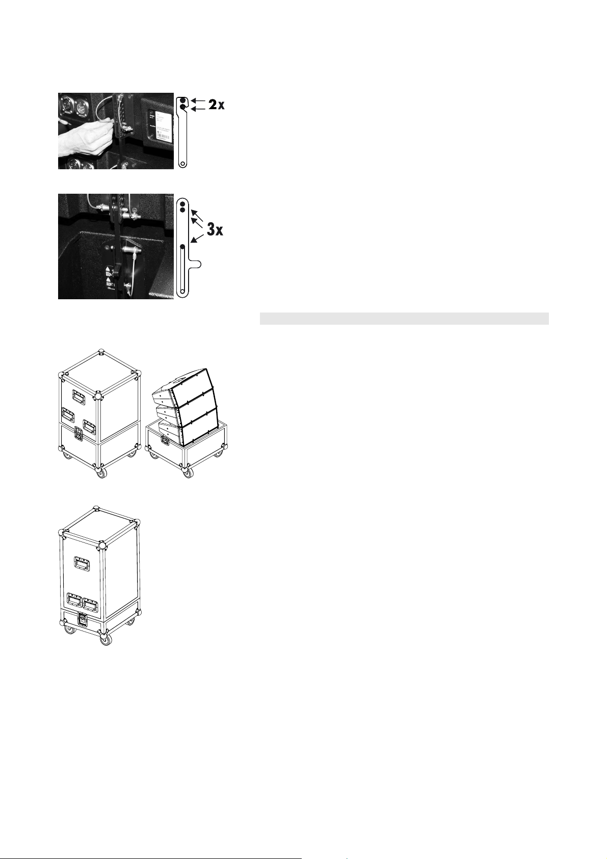
4.1.4. Setup of the E7451 Touring case assembly
E7451 Touring case 4 x T10 assembly
WARNING!
The total center of gravity of the E7451 Touring case assembly
will shift towards the front during assembly.
To prevent the case from moving and tipping over during setup
and/or dismantling we strongly recommend you to proceed as
follows:
- Carry out the setup with two persons with one person
securing the case.
- Ensure no other person remains in the vicinity of the
assembly area.
Preparations
- Prepare the flying cables and link cables according to the number of
amplifier channels and cabinets used.
Order of assembly
1. Suspend the Flying frame
- Suspend the Flying frame according to the chosen type of suspension
as described in section 3.3 on page 15.
- Release the two Locking pins at the front of the frame.
2. Prepare the T10 cabinets in the touring case
- Bring the Touring case into position.
- Slide out the Front links of the upper cabinet.
- Set the splay angles between the cabinets according to your
ArrayCalc simulation as follows:
- Starting with the top cabinet of the assembly first preset the
desired splay angle by inserting one Locking pin.
- Fold up the Splay link of the cabinet below into the rear
rigging strand of the upper cabinet.
- Lift the upper cabinet by hand until the hook of the Splay
link has hooked into the preset Locking pin.
- Insert the second Locking pin (safety pin) to secure the Splay
link.
- Proceed in the same manner until all splay angles of the assembly
are set.
T-Series Rigging manual (1.1 EN) Page 27 of 44
Page 28

3. Attach the Flying frame to the assembly
- Lower the frame onto the assembly until the Front links fit into the
slots at the front of the frame while a second person secures the case
against moving and tipping over.
- Insert and lock the frame's Locking pins through the Front links of the
T10 cabinet on both sides.
- Release the upper Locking pin at the support point for the Splay link
on the center bar of the frame.
- Fold up the Splay link of the cabinet into the track of the frame's
center bar until the link hooks over the Locking pin.
To achieve this you may first have to lower the frame slightly more.
- Lift the frame by hand until the Splay link hooks into the Locking pin
and keep holding the frame in this position.
- Insert the second Locking pin (safety pin) to secure the Splay link.
- Lift the assembly out of the case to a suitable working height to add
the next assembly of T10 cabinets.
4. Attach the next assembly
- Place the next Touring case assembly.
- Set and secure the splay angles between the cabinets as described in
the previous step 2 on page 27.
- Slide out the Front links of the upper cabinet.
- Release the Locking pins at the front of the bottom cabinet of the
previously attached assembly.
- Lower the upper assembly until the Front links fit into the slots at the
front of the upper T10 cabinet while a second person secures the
case against moving and tipping over.
- Insert and lock the Locking pins through the Front links of the T10
cabinet on both sides.
- Slowly lift the entire assembly out of the bottom tray of the case.
T-Series Rigging manual (1.1 EN) Page 28 of 44
Page 29

- On the rear of the assembly preset the desired splay angle at the
rear rigging strand of the bottom cabinet of the upper assembly.
- Raise the bottom assembly and hook the Splay link over the preset
Locking pin.
- Slightly lower the bottom assembly to enable the second Locking pin
(safety pin) to be inserted.
- Insert the second Locking pin to secure the Splay link of the cabinet.
- To add further assemblies proceed in the same manner until the
array is completed.
5. Rig the cabling
- Connect the flying cables and link cables according to the number of
amplifier channels and cabinets used.
- Attach the cable pick depending on the chosen type of suspension
(Single or Dual pickpoint operation setup) as described in section 3.3
Suspension of the Flying frame on page 15.
6. Check the assembly
- Before hoisting the array to its operating position recheck the actual
status of the assembly according to the checklist given in section 5.
Checklist for the assembly of T-Series arrays on page 38.
T-Series Rigging manual (1.1 EN) Page 29 of 44
Page 30

7. Derig the array
WARNING!
Dismantling the assembly of 4 x T10 cabinets while releasing
the Splay link of the upper cabinet and lower the assembly the
entire array could move or swing towards the front in a
sudden.
Therefore we strongly recommend you to proceed as follows:
- Ensure no other person remains in the vicinity of the
assembly area.
- Always secure the array by a second person to safely lower
the array and dismantle it.
- Lower the array to a suitable working height.
- On the rear lift the bottom assembly until the second Locking pin
(securing pin) of the Splay link can be released.
- Lift the assembly further more until the Splay link can be hooked off.
- Carefully lower the assembly while a second person renders support
to secure the entire array against uncontrolled movement and swing.
- Place the bottom tray of the E7451 Touring case below the array.
- Release all safety pins (second Locking pin) at the rear of the bottom
four cabinets before lower them into tray of the case.
- Lower the assembly into the tray while a second person renders
support to secure the case against uncontrolled movement or tipping
over.
- Before releasing the two Locking pins of the Front links which connect
the bottom assembly with the array, a second person renders
support to secure the entire array against uncontrolled movement
and swing.
- Release the Locking pins of the Front links and lift the array slightly.
- Release all Locking pins on the rear rigging strand and fold down the
Splay links so that the cabinets are on block.
- Proceed in the same manner until the array is completely dismantled.
T-Series Rigging manual (1.1 EN) Page 30 of 44
Page 31

E7451 Touring case assembly below T-SUB cabinets
The E7451 Touring case assembly can also be attached below T-SUB
cabinets within a mixed T-SUB/T10 array with T-SUB cabinets at the top
of the array (Please refer to section 4.1.3. T-SUB/T10 Array on page
25).
To attach the assembly below T-SUB cabinets proceed in the same
manner as described in the previous section 4.1.4 following step 4 on
page 28. The same safety instructions apply.
To lower the array and dismantle it, refer to the previous section 4.1.4
following step 7 on page 30. The same safety instructions apply.
T-Series Rigging manual (1.1 EN) Page 31 of 44
Page 32

4.2. T-Series ground stacks
WARNING!
Always secure ground stacked setups against movement and
possible tipping over.
4.2.1. T10 ground stack
Limitation
A maximum of 6 x T10 cabinets with the T Flying frame serving as
ground support are allowed to be set up as ground stack.
Preparations
- Prepare the cables and link cables according to the number of
amplifier channels and cabinets used.
- Ensure the HF sections of the T10 cabinets to be used are set to Line
source.
Order of assembly
1. Prepare the Flying frame
- Place the Flying frame on the ground with the hole index facing
downwards.
- Release the two Locking pins at the front of the frame.
2. Prepare the first T10 cabinet
- Prepare the Front and Splay links of the first T10 cabinet as
described in section 2.4 on page11.
3. Attach the first T10 cabinet
- With the Front links facing downwards attach the cabinet to the slots
at the front of the frame.
- Insert and lock the frame's Locking pins on both sides.
T-Series Rigging manual (1.1 EN) Page 32 of 44
Page 33

4. Set vertical aiming of the first T10 cabinet
0
The two supporting holes on the Flying frame's center bar allow the first
T10 cabinet to be set to a fixed vertical aiming of –2° or 0°.
In this case the hole (drill) of the cabinet's Splay link is used.
Using the upper hole of the supporting holes allows for a vertical aiming
of –2° the bottom hole for 0°.
- Fold out and insert the Splay link of the cabinet into the track of the
center bar of the frame and align the hole of the Splay link with the
desired supporting hole of the frame.
- Insert one of the frame's Locking pins to fix the Splay link in place.
- The second Locking pin is not required and should be stored in the
remaining hole.
5. Add further T10 cabinets
- Preselect the desired splay angle on the rear rigging strand of the
bottom cabinet.
- Release the Locking pins at the front of the bottom cabinet.
- Prepare the next cabinet.
- With the Front links facing downwards attach the cabinet to the slots
at the front of the bottom cabinet.
- Insert and lock the Locking pins of the Front links on both sides.
- Fold out the Splay link of the cabinet and connect it to the cabinet
below as follows:
- Lower the back of the cabinet until the Splay link hooks over
the preset Locking pin.
- Raise the back of the cabinet until the Splay link is
completely hooked into the Locking pin.
- Insert the second Locking pin (safety pin) to fix the desired
splay angle.
To attach further T10 cabinets, proceed in the same manner until the
assembly is completed.
Note:
The two Locking pins at the top cabinet of the stack are
not used. They should be stored in two of the remaining
holes on the rear rigging strand.
T-Series Rigging manual (1.1 EN) Page 33 of 44
Page 34

6. Rig the cabling
- Connect the cables and link cables according to the number of
amplifier channels and cabinets used.
7. Check the assembly
- Recheck the assembly according to the checklist given in section 5.
Checklist for the assembly of T-Series arrays on page 38.
8. Derig the ground stack
- To dismantle the ground stack, follow the assembly instructions in
reverse order. The same safety instructions apply.
4.2.2. T-SUB/T10 ground stack
Limitation
A maximum of 3 x T10 cabinets on top of maximum 2 x T-SUB cabinets
serving as ground support are allowed to be set up as ground stack.
Preparations
- Prepare the cables and link cables according to the number of
amplifier channels and cabinets used.
- Ensure the HF sections of the T10 cabinets to be used are set to Line
source.
Order of assembly
1. Stack the two T-SUB cabinets
- Interconnect the cabinets with their Front and Rear links.
2. Attach the first T10 cabinet
- Slide out the Front links of the T-SUB cabinet.
- Release the Locking pins at the front of the T10 cabinet.
- Attach the T10 cabinet to the Front links of the T-SUB cabinet.
- Insert and lock the Locking pins for the Front links on both sides.
T-Series Rigging manual (1.1 EN) Page 34 of 44
Page 35

3. Set vertical aiming of the first T10 cabinet
-2°
-1°
The vertical aiming of the first T10 cabinet connected to the T-SUB
depends on the chosen hole of the T-SUB's Rear link.
Using the upper hole of the Rear link allows for angles of –2° or –1°.
Using the bottom hole allows for angles of 0°, +1°, +2°, +3°, +4° or
+6° corresponding to the scale on the T10 rear rigging strand.
To apply the angles proceed as follows:
- On the rear release the Locking pins of the Splay link of the T10
cabinet and fold up the Splay link.
- Release the Locking pin of the Rear link of the T-SUB.
- Slide out the Rear link up to its stop position.
- Insert and lock the Locking pin for the Rear link on the T-SUB cabinet.
- Align the T10 cabinet to the desired angle as shown in the graphic
above.
- Insert the Locking pin for the Rear link on the T10 cabinet.
Note:
The second Locking pin is not used. It should be stored in
one of the remaining holes on the rear rigging strand.
4. Add further T10 cabinets
- Slide out the Front links on the currently attached T10 cabinet.
- Prepare the next cabinet and preselect the desired splay angle on
the rear rigging strand of the next T10 cabinet.
- Release the Locking pins at the front of the cabinet.
- Attach the cabinet to the Front links of the bottom cabinet.
- Insert and lock the Locking pins for the Front links on both sides.
T-Series Rigging manual (1.1 EN) Page 35 of 44
Page 36

- On the rear fold up the Splay link of the bottom cabinet and connect
it to the upper cabinet as follows:
- Lower the back of the upper cabinet until the Splay link
hooks over the preset Locking pin.
- Raise the back of the cabinet until the Splay link is
completely hooked into the Locking pin.
- Insert the second Locking pin (safety pin) to secure the Splay
link.
- To attach further T10 cabinets, proceed in the same manner until the
assembly is completed.
5. Rig the cabling
Connect the cables and link cables according to the number of amplifier
channels and cabinets used.
6. Check the assembly
Recheck the assembly according to the checklist given in section 5.
Checklist for the assembly of T-Series arrays on page 38.
T-Series Rigging manual (1.1 EN) Page 36 of 44
Page 37

7. Derig the ground stack
WARNING!
The total center of gravity of the T-SUB/T10 ground stack is
located close to the front of the stack.
To prevent the stack from tipping over while dismantling it we
recommend you to proceed as follows:
- Standing in front of the ground stack first release the Locking pins of
the Splay link of the first T10 cabinet and fold out the Splay link.
- Release the Locking pins for the Font links on both sides while holding
the cabinet.
- Remove the cabinet.
- Proceed in the same manner until all T10 cabinets are dismantled.
4.2.3. T-SUB stacks
Conventional T-SUB stacks are set up in the same manner as described
in the previous section 4.2.2 following step 1 on page 34. For
conventional ground stacks of T-SUB cabinets we also recommend
connecting the cabinets using their Rear links.
T-Series Rigging manual (1.1 EN) Page 37 of 44
Page 38

5. Checklist for the assembly of T-Series arrays
5.1. System and safety checks
5.1.1. Flown arrays
Before hoisting the array to its operating position recheck the actual
status of the assembly as follows:
- Check the attachment of the Load adapter(s) to the Flying frame and
ensure all Locking pins are properly locked.
- Check the attachment of the secondary safety device at the Flying
frame (refer to section 3.4 on page 17).
- Check the attachment of the Flying frame to the first cabinet (T10 or
T-SUB Front and Splay/Rear links) and ensure all Locking pins are
properly locked.
- Check the attachment of all Front links on both sides of the cabinets
and ensure all Locking pins are properly locked.
- Check the splay angles.
- Check the attachment of the Splay/Rear links at the rear of the
cabinets and ensure all Locking pins are properly locked.
- In "Single pickpoint operation" check the desired total vertical aiming
of the entire array using a inclinometer.
5.1.2. Ground stacks
- Check the attachment of all Front links on both sides of the cabinets
and ensure all Locking pins are properly locked.
- Check the splay angles.
- Check the attachment of the Splay/Rear links at the rear of the
cabinets and ensure all Locking pins are properly locked.
5.1.3. Wiring
- Check the wiring.
If the amplifiers are already wired and powered on, use their System
check function or channel mute switches and a test signal to check the
correct functioning and routing of all channels and cabinets.
T-Series Rigging manual (1.1 EN) Page 38 of 44
Page 39

5.2. Hoisting and securing the array
When all the mechanical adjustments, system checks and safety checks
have been made the array can be hoisted up to its operating position.
When hoisting the array, ensure that the loudspeaker cables do not get
caught anywhere. The cables can be strapped together with the motor
cable to form a loom while the system is hoisted.
The chain hoist motors must raise the system slowly and evenly so that it
does not swing or move from side to side during hoisting.
When the array is in its final operating position the secondary safety
must be applied. A detailed description is given in section 3.4
Secondary safety on page 17.
T-Series Rigging manual (1.1 EN) Page 39 of 44
Page 40

6. Wind loads
When planning an open-air event it is essential to obtain current
weather and wind information.
When loudspeaker arrays are flown in an open-air environment,
possible wind effects must be taken into account. Wind load produces
additional dynamic forces acting on the rigging components and the
suspension, which may lead to a dangerous situation.
If according to the forecast wind forces higher than 5 bft are possible,
the following actions have to be taken:
- The actual on-site wind speed has to be monitored permanently. Be
aware that wind speed typically increases with height above ground.
- Suspension and securing points of the array should be designed to
support double the static load in order to withstand any additional
dynamic forces.
WARNING!
Flying loudspeakers overhead at wind forces higher than 6 bft
is not recommended.
If the wind force exceeds 8 bft there is a risk of
mechanical damage to the components which may
lead to a dangerous situation for persons in the
vicinity of the flown array.
- Stop the event and make sure that no person remains in the
vicinity of the array.
- Lower and secure the array.
The following wind speed scale according to Beaufort provides an
impression of the effects of the different wind forces (bft).
bft knots km/h mph Description Effects on land
0 0-1 0-1 0-1 Calm
1 1-3 1-5 1-3 Light Air
2 4-6 6-11 4-7 Light breeze
3 7-10 12-19 8-12 Gentle breeze
4 11-16 20-28 13-18 Moderate breeze
5 17-21 29-38 19-24 Fresh breeze
6 22-27 39-49 25-31 Strong breeze
7 28-33 50-61 32-38 Near gale
8 34-40 62-74 39-46 Gale
9 41-47 75-88 47-54 Severe gale
10 48-55 89-102
55-63
Storm
11 56-63 102-117 64-72 Violent storm
12 > 64 > 117,0 > 72 Hurricane
Smoke rises vertically.
Direction of wind shown by smoke drift, but not by wind vanes.
Wind felt on face; leaves rustle; ordinary vanes moved by wind.
Leaves and small twigs in constant motion; wind extends light
flag.
Raises dust and loose paper; small branches are moved.
Small trees in leaf begin to sway; crested wavelets form on
inland waters.
Large branches in motion; whistling heard in telegraph wires;
umbrellas used with difficulty.
Whole trees in motion; inconvenience felt when walking against
the wind.
Breaks twigs off trees; generally impedes progress.
Slight structural damage occurs (chimney-pots and slates
removed).
Trees uprooted; considerable structural damage occurs.
Accompanied by wide-spread damage.
Heaviest damage and destruction.
Tab. 1: Wind force and its effects on land
T-Series Rigging manual (1.1 EN) Page 40 of 44
Page 41

7. Care and maintenance / Disposal
7.1. Transport / Storing
During transport ensure the rigging components are not stressed or
damaged by mechanical forces. Use suitable transport cases.
The surface treatment temporarily protects the rigging components
against moisture. However, ensure the components are in a dry state
when storing and transporting them.
7.2. Visual and functional inspection
Cabinet enclosure
- Visual inspection of all fitting plates for obvious damage (e.g. cracks
or corrosion).
- Inspection of all fitting plates including the front grills to ensure they
are securely attached.
Locking pins
- Visual inspection for deformation of the component.
- Inspection for missing ball bearings and damage.
- Functional inspection of the release mechanism to ensure it operates
properly.
- Regularly lubricate the Locking pins using WD-40®or a similar
product.
Front and Splay (Rear) links
Visual inspection for deformation and damage (e.g. cracks and
corrosion) including all holes of the component.
Flying frame
- Visual inspection regarding deformation and damage (e.g. cracks
and corrosion) including all holes of the component.
- Regularly check the flatness of the Flying frame. For this purpose
place the Flying frame on a flat surface and visually check the frame
for deformation and/or torsion. In case obvious deformation and/or
torsion contact d&b audiotechnik for further advice.
Load adapter
- Visual inspection for deformation and damage (e.g. cracks and
corrosion) including all holes of the component.
7.3. Disposal
Please dispose of this product according to the respective national
regulations.
Ensure that damaged rigging components are disposed of so that they
cannot be used again.
T-Series Rigging manual (1.1 EN) Page 41 of 44
Page 42

EC Declaration of Conformity
within the meaning of the EC Machine Directive 98/37/EEC
We hereby declare that the equipment designated below is designed and
built in the version sold by us in such a way as to comply with the relevant
fundamental safety and health criteria of the applicable EC Directive(s).
This declaration shall cease to be valid if alterations are made to the
equipment without our prior agreement.
This declaration covers:
d&b Z5370, T Flying frame including:
- d&b T Load adapter
- d&b T Locking pins
d&b T-Series loudspeaker cabinets (with integrated rigging components):
- d&b Z0550, T10 loudspeaker
- d&b Z0560, T-SUB loudspeaker
Relevant EC Directives:
EC Machine Directive 98/37/EC
National standards and technical specifications applied, in
particular:
DIN EN ISO 12 100, BGV C1
Backnang 2009-01-19
(Frank Bothe, Director)
d&b audiotechnik GmbH, Eugen-Adolff-Str. 134, D-71522 Backnang, Germany, Phone +49-7191-9669-0, Fax +49-7191-95 00 00_______
Page 43

Page 44

D2993.EN .01, 02/2009 © d&b audiotechnik GmbH
d&b audiotechnik GmbH, Eugen-Adolff-Str. 134, D-71522 Backnang, Germany, Phone +49-7191-9669-0, Fax +49-7191-95 00 00_______
 Loading...