

Page 1
A.E.B. INDUSTRIALE s.r.l.
Via Brodolini, 8 - 40056 Crespellano (Bo) - ITALIA
Tel. + 39 051 969870 - Fax. + 39 051 969725
Internet: www.dbtechnologies.com
E-mail: info@dbtechnologies-aeb.com
BB
dd
TECHNOLOGIESTECHNOLOGIES
MANUALE D’USO
USER MANUAL
BEDIENUNGSANLEITUNG
CARACTERISTIQUES TECHNIQUES
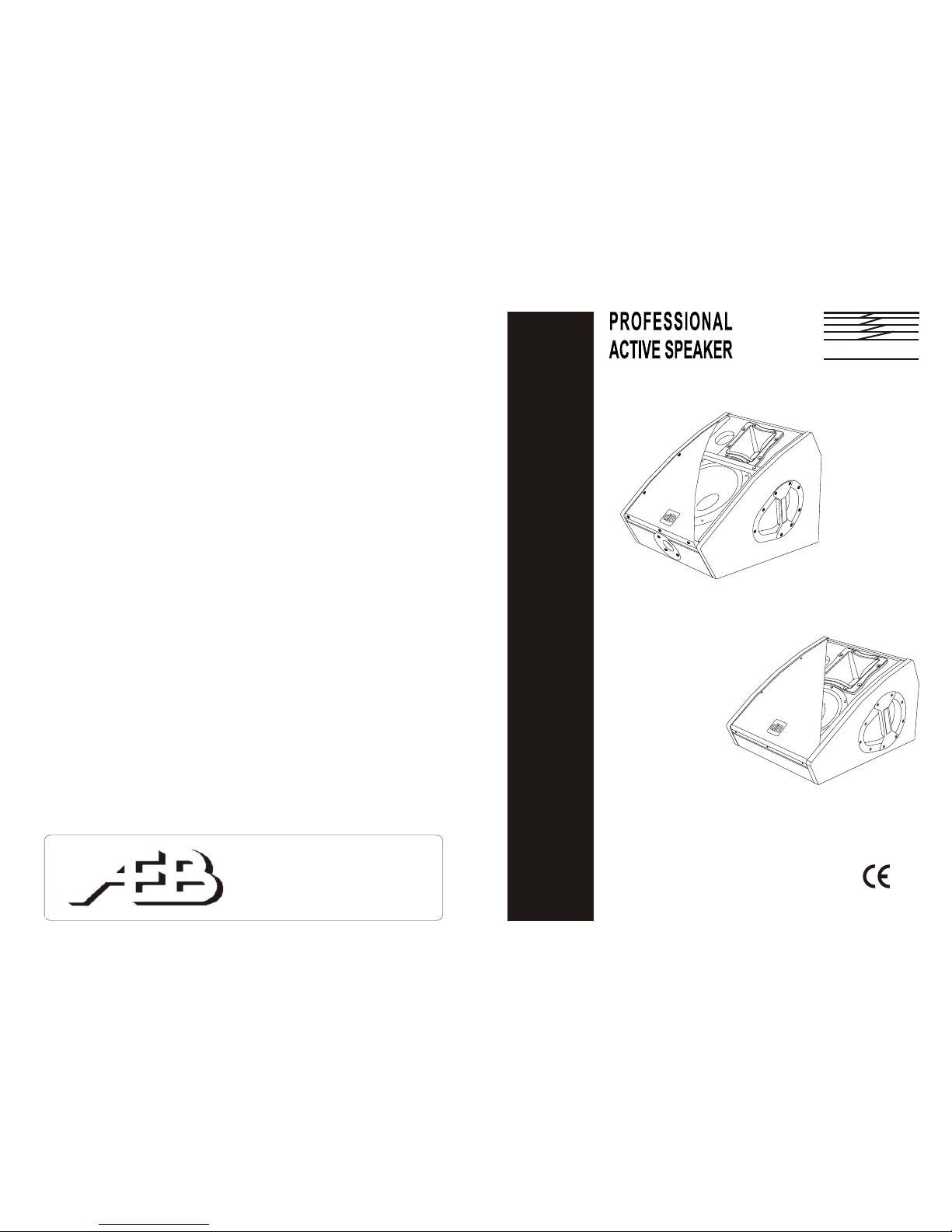
PROFESSIONAL
ACTIVE SPEAKER
PROFESSIONAL
ACTIVE SPEAKER
Manufactured in India under
dB Technologies control
Manufactured in India under
dB Technologies control
COD. 420120125
M12-4 PLUS
STAGE MONITORSTAGE MONITOR
seriesseries
M10-2 PLUS
Page 2

1
ItalianoItalianoItaliano
Manuale d’usoManuale d’uso
ItalianoItalianoItaliano
Manuale d’usoManuale d’uso
2
Carrelli e sostegni
Utilizzare solo carrelli, basamenti, treppiedi, staffe o sostegni consigliati dal produttore o forniti in
dotazione all’apparecchio. Quando viene utilizzato un carrello, usare cautela durante lo spostamento
dell’apparecchio per evitare infortuni a causa di capovolgimenti.
Periodi di non utilizzo
Staccare l’apparecchio dalla presa d’alimentazione nel caso di lampi e tuoni o nel caso di un lungo
periodo di non utilizzo.
Ingresso di liquidi e oggetti nell' apparecchio
Assicurarsi che oggetti non cadano sull’apparecchio o che non si versino liquidi attraverso le
aperture.
Danni che richiedono l'assistenza
Per qualunque riparazione rivolgersi a personale qualificato. Un intervento tecnico é richiesto quando:
- l’apparecchio e’ stato danneggiato;
- il cavo di alimentazione o la presa siano danneggiati;
- sono caduti oggetti sull’apparecchio o liquidi siano entrati all’interno
- l'apparecchio è stato esposto alla pioggia o all’umidita’:
- l'apparecchio non sembra funzionare normalmente oppure ha cambiato le sue prestazioni;
- l'apparecchio è caduto.
Manutenzione
L'utente non deve tentare di riparare l'apparecchio al di là di quello descritto nelle istruzioni. Tutte le
altre riparazioni devono essere eseguite da personale qualificato.
IMPORTANTE
Il presente manuale costituisce parte integrante del prodotto e deve accompagnare quest’ultimo
anche nei passaggi di proprietà, per permettere al nuovo proprietario di conoscere le modalità
d’installazione e d’utilizzo e le avvertenze per la sicurezza.
L’installazione errata del diffusore esime la dB Technologies da ogni responsabilità.
PRECAUZIONI PER L’UTILIZZO
- Evitate di far lavorare l’amplificatore interno al diffusore in sovraccarico per lungo tempo.
- Non usare la forza sugli organi di comando (tasti, controlli, ecc.).
ATTENZIONE
- Collocate il diffusore in modo stabile e sicuro, così da evitare qualsiasi condizione di pericolo
per l’incolumità di persone o strutture.
COLLEGAMENTI
ATTENZIONE
- Per il collegamento del diffusore si raccomanda di rivolgersi a personale qualificato ed
addestrato, ossia personale avente conoscenze tecniche o esperienza o istruzioni specifiche
sufficienti per permettergli di realizzare correttamente le connessioni e prevenire i pericoli
dell’elettricità.
- Per evitare il rischio di shock elettrici, il diffusore deve essere alimentato dalla tensione di rete
solo dopo aver terminato tutti i collegamenti.
- Prima di alimentare il diffusore è buona norma ricontrollare tutte le connessioni.
- Tutto l’impianto di sonorizzazione dovrà essere realizzato in conformità con le norme e le leggi
vigenti in materia di impianti elettrici.
AVVERTENZA
- Per evitare che fenomeni induttivi diano luogo a ronzii, disturbi e compromettano il buon
funzionamento del diffusore, i cavi che trasmettono segnali microfonici o segnali a livello linea
(es. 0 dB/V) devono essere schermati e non devono essere posti in prossimità di:
1) apparecchiature che producono forti campi magnetici (es. grossi trasformatori di
alimentazione).
2) conduttori dell’energia elettrica.
3) linee che alimentano diffusori.
PROTEZIONI
Il diffusore è provvisto di un esclusivo sistema di protezione che protegge gli altoparlanti del diffusore
contro surriscaldamenti, in grado di assicurare la massima affidabilità in tutte le applicazioni
professionali. Un sofisticato sistema di gestione dell’amplificatore provvede inoltre alle protezioni
“limiter”, termica e contro cortocircuiti.
ISTRUZIONI DI SICUREZZA
AVVERTENZA: PER RIDURRE IL RISCHIO DI SCOSSA
ELETTRICA, NON TOGLIERE IL
COPERCHIO (O IL PANNELLO
POSTERIORE). ALL’INTERNO NON SONO
CONTENUTE PARTI RIPARABILI
DALL’UTENTE; AFFIDARE LE RIPARAZIONI
A PERSONALE QUALIFICATO.
ATTENZIONE: PER RIDURRE IL RISCHIO DI INCENDIO O
DI SCOSSA ELETTRICA, NON ESPORRE
QUESTO APPARECCHIO ALLA PIOGGIA O
ALL’UMIDITÀ.
Questo simbolo, dove compare, ha lo scopo di avvisare l’utente di presenza di
tensione pericolosa all’interno del prodotto che può essere di portata sufficiente a
costituire un rischio di scossa elettrica per le persone.
Questo simbolo, dove appare, ha lo scopo di avvisare l’utente di presenza di
importanti istruzioni d’uso e manutenzione (assistenza) nella documentazione che
accompagna l’apparecchio.
ISTRUZIONI DI SICUREZZA NEL DETTAGLIO:
Leggere queste istruzioni
Tutte le istruzioni di sicurezza e di funzionamento devono essere lette prima di mettere in funzione
l'apparecchio.
Conservare queste istruzioni
Le istruzioni di sicurezza e di funzionamento devono essere conservate per ogni riferimento futuro.
Tenere conto di tutti gli avvertimenti
Tutte le avvertenze sull'apparecchio e le istruzioni di funzionamento devono essere seguite
fedelmente.
Seguire tutte le istruzioni
Tutte le istruzioni di funzionamento e per l'utente devono essere seguite.
Acqua e umidità
L'apparecchio non deve essere usato in prossimità di acqua (per esempio vicino a vasche da bagno,
lavabi, lavelli da cucina, vasche per il bucato, su pavimento bagnato oppure in prossimità di piscine….)
A meno che espressamente consentito.
Pulizia
Pulire solo con un panno secco. Per la pulizia delle parti esterne evitare l’uso di diluenti, alcool, benzina
o altre sostanze volatili.
Ventilazione
Non ostruire alcuna delle aperture di ventilazione. Installare questo apparecchio in accordo con le
istruzioni fornite dal produttore. L’apparecchio deve essere posto in modo tale che la sua collocazione
o posizione non interferisca con l’adeguata ventilazione.
Calore
Non installare l'apparecchio in prossimità di fonti di calore come radiatori, stufe oppure altri apparecchi
(inclusi gli amplificatori) che producono calore.
Messa a terra
Non pregiudicare la polarizzazione o la messa a terra della spina. Per evitare il rischio di shock elettrici
le parti metalliche del diffusore devono essere connesse a terra. Una spina polarizzata ha due poli di
cui uno più largo dell’altro. Una spina con la messa a terra ha due poli ed un terzo polo per la messa a
terra. Il polo più largo o il terzo polo sono forniti per la vostra sicurezza. Se la spina non si inserisce nella
vostra presa di rete, rivolgersi ad un elettricista per la sostituzione della presa obsoleta.
L’altoparlante dovrà essere collegato a una presa di alimentazione principale con il collegamento a
terra.
Alimentazione
L'apparecchio deve essere collegato solo al tipo di alimentazione descritto nelle istruzioni d'uso
oppure riportato sull'apparecchio stesso. Per non compromettere la sicurezza del diffusore,
quest’ultimo deve essere connesso alla rete di alimentazione solamente tramite il cavo di
alimentazione fornito a corredo.
L’interruttore principale posto sul retro (DPDT) è usato per sconnettere l’apparecchio.
Cavo di alimentazione
Proteggere il cavo d’alimentazione dalla possibilità di essere calpestato o pizzicato, in particolare in
prossimità’ della spina e nel punto in cui si inserisce nell’apparecchio.
Accessori
Utilizzare solo con accessori specificati dal produttore.
"AVIS"
RISQUE DE CHOC ELECTRIQUE
NE PAS OUVRIR
POUR PREVENIR TOUT RISQUE DE FEU
REPLACER UN FUSIBLE
DE MÊME CARACTERISTIQUES
CET APPAREIL DOIT ÊNTRE RELIÉ A LA TERRE
"CAUTION"
TO PREVENT ELECTRICAL SHOCK
DO NOT REMOVE COVER
TO PREVENT RISK OF FIRE
REPLACE FUSES WITH
SAME TYPE AND RATINGS
THIS APPARATUS MUST BE EARTHED
Page 3
COMANDI E FUNZIONI
PANNELLO AMPLIFICATORE (FIG. 1)
1) CONTROLLO “VOLUME”
Questo controllo regola il volume in uscita dal diffusore.
Tale controllo non influisce sul livello del segnale in uscita (link).
2) INDICATORE LUMINOSO “LIMITER”
L’indicatore luminoso “LIMITER” s’illumina di colore rosso durante la fase di
accensione (per alcuni secondi) e all’intervento del limiter audio interno.
Questo evita la distorsine dell'amplificatore e protegge gli altoparlanti contro
sovraccarichi.
3) INDICATORE LUMINOSO “POWER”
L’indicatore luminoso “POWER” s’illumina di colore verde per indicare l’accensione
e il corretto funzionamento dell’amplificatore.
4) CONTROLLO EQUALIZZAZIONE “EQUALIZATION”
Questo controllo permette una equalizzazione del diffusore.
La posizione centrale “FLAT” permette una riproduzione sonora lineare del
diffusore. Ruotando il controllo verso “VOICE” la curva di risposta del diffusore
esalta le medie frequenze mentre ruotando il controllo verso ”MUSIC” si esaltano le
basse e le alte frequenze.
Tale controllo non influisce sul livello del segnale d’uscita (link) .
5) CONNETTORI “BALANCED INPUTS LINK”
Questi connettori possono essere utilizzati come ingressi bilanciati per il
collegamento di sorgenti audio a livello linea (0dB) (es. preamplificatore, mixer,
registratore, lettore CD, strumento musicale, ...)
Questi connettori sono collegati in parallelo e possono essere utilizzati per rinviare il
segnale audio ad altri diffusori amplificati, registratori o amplificatori supplementari.
6) INTERRUTTORE GENERALE “POWER”
L’interruttore permette l’accensione e lo spegnimento del diffusore.
7) PRESA DI ALIMENTAZIONE “MAINS ”
Consente la connessione del cavo di alimentazione fornito in dotazione.
8) PORTA FUSIBILE “FUSE”
Alloggio per fusibile di rete.
9) CAMBIO TENSIONE “VOLTAGE SELECTOR”
Permette di selezionare la tensione di alimentazione del diffusore (240V/120V).
Questo selettore viene pre - impostato e protetto dalla ditta costruttrice.
SPECIFICHE TECNICHE E DIMENSIONI
ItalianoItalianoItaliano
Manuale d’usoManuale d’uso
4
ItalianoItalianoItaliano
Manuale d’usoManuale d’uso
3
DATI TECNICI M10-2 PLUS M12-4 PLUS
Sistema ATTIVO / BI-AMP ATTIVO / BI-AMP
Tipologia amplificatore ALTI - classe AB ALTI - classe AB
BASSI - classe H BASSI - classe H
Potenza RMS 150W LF + 50W HF 250W LF+50W HF
Potenza musicale 300W LF + 100W HF 500W LF+100W HF
Risposta in frequenza (-3dB) 70 - 19.000 Hz 68 - 19.000 Hz
Crossover Ft 2000 Hz Ft 2000 Hz
DR 12 dB/oct CD 12 dB/oct
W 12dB/oct W 12dB/oct
Pressione sonora (SPL) 120 dB max 126 dB max
Componenti 1 x woofer 10" 1 x woofer 12”
voice coil 2” voice coil 2”
1 x driver 1" 1 x compress. Driver 1,4”
voice coil 1” exit voice coil 1” exit
Dispersione 90°x70° (ruotabile) 90°x70° (ruotabile)
Sensibilità di ingresso 0dB 0dB
Impedenza ingresso bilanciato 30KW 30KW
Alimentazione vedi targa box
Dimensioni (LxHxP) 380x286x493 mm 400x387x525 mm
Peso 13,7 Kg 18,4 Kg
Inserti per appendibilita’ --- 10MA x 3 punti
Supporto piantana --- D36mm
MODIFICA ANGOLO DI COPERTURA TROMBA
I diffusori vengono forniti dalla ditta costruttrice sempre con la tromba orientata
- svitare le viti di fissaggio della rete
- svitare le otto viti di fissaggio della tromba
- ruotare la tromba nella posizione desiderata (non estrarre mai il blocco tromba dal
diffusore)
- riavvitare le viti di fissaggio della tromba
- inserire nuovamente la rete negli appositi scassi laterali e riavvitare le viti.
90°in senso
orizzontale.
Se si desidera modificare la posizione della tromba è necessario (FIG. 2):
INSTALLAZIONE DEL DIFFUSORE
ATTENZIONE
Installare il diffusore in modo stabile e sicuro, così da evitare qualsiasi condizione di
pericolo per l’incolumità di persone e strutture.
Prima di sospendere il diffusore controllare tutti i componenti da utilizzare, che non devono
presentare danni, deformazioni, parti mancanti o danneggiate che possono ridurre la
sicurezza dell’installazione.
Nell’utilizzo all’aperto evitare luoghi esposti alle intemperie.
Il diffusore viene fornito dalla ditta costruttrice predisposto per l’utilizzo :
- a pavimento (come monitor) (FIG.3)
- su supporto piantana - solo per M12-4 PLUS (FIG.4)
- appeso con golfari - solo per M12-4 PLUS (FIG.5)
Page 4
5
EnglishEnglishEnglish
6
user manualuser manual
SAFETY INSTRUCTIONS
CAUTION: TO REDUCE THE RISK OF
ELECTRICAL SHOCK, DO NOT
REMOVE THE COVER (OR BACK). NO
USER SERVICEABLE PARTS INSIDE;
REFER SERVICING TO QUALIFIED
PERSONNEL.
WARNING: TO REDUCE THE RISK OF FIRE OR
ELECTRICAL SHOCK. DO NOT
EXPOSE THIS APPARATUS TO RAIN
OR MOISTURE.
This symbol, wherever it appears, alerts you to the presence of uninsulated
dangerous voltage inside the enclosure - voltage that may be sufficient to constitute
a risk of shock.
This symbol wherever it appears, alerts you to important operating and
maintenance instructions in the accompanying literature. Read the manual.
DETAILED SAFETY INSTRUCTIONS:
Read these instructions
All the safety and operation instructions should be read before the apparatus is operated.
Keep these instructions
The safety and operating instructions should be retained for future reference.
Heed all warnings
All warnings on the apparatus and in the operating instructions should be adhered to
Follow all instructions:
All operation and user instructions should be followed
Water and moisture
Do not use this apparatus near water (e.g. near a bathtub, washbowl, kitchen sink, laundry tub, in a wet
basement, or near a swimming pool etc.) except expressly allowed
Cleaning
Clean only with a dry cloth. Do not use solvents, alcohol, benzene or volatile substances for cleaning
the exterior parts.
Ventilation
Do not block any of the ventilation openings. Install in accordance with the manufacturers instructions.
The apparatus should be situated so that its location or position does not interfere with its proper
ventilation.
Heat
Do not install the apparatus near any heat sources such as radiators, heat registers, stoves, or other
apparatus (including amplifiers) that produce heat.
Grounding or Polarization
Do not defeat the safety purpose of the polarized or grounding/type plug. To prevent the risk of
electrical shock, the metallic parts of the speaker must be earthed. A polarized plug has two blades
with one wider than the other. A grounding type plug has two blades and a third grounding prong. The
wide blade or the third prong are provided for your safety. When the provided plug does not fit into your
outlet, consult an electrician for replacement of the obsolete outlet.
Speaker shall be connected to a MAINS socket outlet with a protective earthing connection.
Power Source
The apparatus should be connected to a power supply only of the type described in the operating
instructions or as marked on the apparatus. In order not to jeopardize the safety of the speaker, it must
only be connected to the mains using the power cable provided.
DPDT Mains Switch is used as the disconnect device located at the rear.
Power Cord Protection
Protect the power cord from being walked on or pinched particularly al plugs, convenience receptacles,
and the point where they exit from the apparatus.
Accessories
Only use attachments/accessories specified by the manufacturer.
"AVIS"
RISQUE DE CHOC ELECTRIQUE
NE PAS OUVRIR
POUR PREVENIR TOUT RISQUE DE FEU
REPLACER UN FUSIBLE
DE MÊME CARACTERISTIQUES
CET APPAREIL DOIT ÊNTRE RELIÉ A LA TERRE
"CAUTION"
TO PREVENT ELECTRICAL SHOCK
DO NOT REMOVE COVER
TO PREVENT RISK OF FIRE
REPLACE FUSES WITH
SAME TYPE AND RATINGS
THIS APPARATUS MUST BE EARTHED
Carts and stands
Use only with a cart, stand, tripod, bracket, or table specified by the manufacturer, or sold with the
apparatus. When a cart is used, use caution when moving the cart/apparatus combination to avoid
injury from tip-over.
Non-use Periods:
Object and Liquid Entry
Damage Requiring Service
Servicing:
IMPORTANT NOTES
This manual is to be considered an integral part of the product, and must always accompany the
speaker when it changes ownership as a reference for correct installation and operation as well as for
the safety regulations.
dB Technologies will not assume any responsibility for incorrect installation of the speaker.
OPERATING PRECAUTIONS
- Do not force the amplifier incorporated in the speaker to work in overload for extended periods
of time.
- Never force the control elements (switches, controls, etc.).
CAUTION
- Make sure that the speaker is positioned in a stable and secure way in order to avoid any
dangerous conditions for persons or objects.
CONNECTION
- For connecting the speaker, use only qualified and experienced personnel having sufficient
technical knowledge or specific instructions for making the connections correctly and thus
preventing electrical dangers.
- To prevent the risk of electrical shock, the speaker must only be supplied from the mains after all
connections have been completed.
- Before powering up the speaker, it is advisable to re-check all the connections, making sure in
particular that there are no short circuits.
- The entire sound system must be designed and installed in compliance with the current
standards and regulations regarding electrical systems.
CAUTION
- To prevent inductive phenomena from giving rise to hum or disturbance which would jeopardize
efficient speaker operation, the cables that transmit microphone signals or line level signals
(e.g. 0 dB/V) must be screened and should not be run in the vicinity of:
1) Equipment that produces strong magnetic fields (e.g. large power supply transformers)
2) Electrical energy conductors
3) Lines that supply speakers.
PROTECTION SYSTEM
The speaker is equipped of a exclusive system, which protects the loudspeakers against overheating,
ensuring the maximum reliability in all professional applications. In addition, a sophisticated system
incorporated in the amplifier handles the limiter circuits and the protection against overheating and
short circuits.
Unplug this apparatus during lightning storms or when unused for long periods of time.
Care should be taken so that objects do not fall and liquids are not spilled into the enclosure through
openings.
Refer all servicing to qualified service personnel. Servicing is required when:
- the apparatus has been damaged in any way;
- the power-supply cord or the plug has been damaged;
- the liquid had been spilled or objects have fallen into the apparatus;
- the apparatus has been exposed to rain or moisture
- the apparatus does not operate normally or exhibits a marked change in performance;
- the apparatus had been dropped.
The user should not attempt to service the apparatus beyond that is described in the Operating
Instructions. All other servicing should be referred to qualified service personnel.
CAUTION
EnglishEnglishEnglish
user manualuser manual
Page 5

7
EnglishEnglishEnglish
user manualuser manual
EnglishEnglishEnglish
8
COMMANDS AND FUNCTIONS
1) “VOLUME” CONTROL
The knob regulates the diffuser's volume.
This control does not affect the output “LINK” levels.
2) “LIMITER” INDICATOR LIGHT
The “LIMITER” indicator light comes on red during start (for a few seconds) and
when the internal audio limiter engages. This avoids the amplifier's distortion and
protects the loudspeakers against overloads.
3) “POWER” INDICATOR LIGHT
The “POWER” indicator light comes on green to indicate that the amplifier is
switched on and it is working properly.
5) “BALANCED INPUTS LINK” CONNECTORS
These balanced inputs can be used to connect audio sources at line level (0dB)
(eg. preamplifier, mixer, recorder, CD player, musical instrument, ...).
The balanced connector is connected in parallel and can be used to send the audio
signal to other amplified speakers, recorders or supplementary amplifiers.
6) POWER SWITCH “POWER”
This switch can be used to switch the diffuser on and off.
7) POWER CABLE SOCKET “MAINS”
Used for connecting the power cable supplied.
8) FUSE CARRIER “FUSE”
Mains fuse housing.
9) VOLTAGE CHANGE “VOLTAGE SELECTOR”
For changing the power voltage of the speaker (240V/120V).
This switch is preset and protected by the manufacturer.
AMPLIFIER PANEL (PIC.1)
4) EQUALIZATION CONTROL
This control permits the equalization of the speaker.
The "FLAT" central position permits a linear sound reproduction of the speaker. By
turning the control towards “VOICE”, the response curve of the speaker highlights
the mid frequencies while if the control is turned towards ”MUSIC”, the low and high
frequencies are highlighted.
This control does not affect the level of the output signal (link).
ROTATING HORN
Speakers are always supplied by the manufacturer with the horn driver positioned
horizontal at 90°.
If you wish to change the coverage angle (PIC. 2):
- undo the fixing screws of the grille
- remove the front protective grille by slightly pressing on one side and taking the
grille off the special slots
- undo the eight fixing screws of the horn
- rotate the horn in the desired position (the horn should never be removed from the
loudspeaker)
- tighten the fixing screws of the horn
- put the grille back in the special side slots and tighten the screws of the grille.
TECHNICAL DATA AND DIMENSIONS
TECHNICAL DATA M10-2 PLUS M12-4 PLUS
System ACTIVE / BI-AMPS ACTIVE / BI-AMPS
Type of amplifier HIGH - class AB HIGH - class AB
LOW - class H LOWI - class H
RMS Power 150W LF + 50W HF 250W LF+50W HF
Musical power 300W LF + 100W HF 500W LF+100W HF
Frequency response (-3dB) 70 - 19.000 Hz 68 - 19.000 Hz
Crossover Ft 2000 Hz Ft 2000 Hz
DR 12 dB/oct CD 12 dB/oct
W 12dB/oct W 12dB/oct
Sound pressure (SPL) 120 dB max 126 dB max
Components 1 x woofer 10" 1 x woofer 12”
voice coil 2” voice coil 2”
1 x driver 1" 1 x compress. Driver 1,4”
voice coil 1” exit voice coil 1” exit
Dispersion 90°x70° (rotary) 90°x70° (rotary)
Input sensitivity 0dB 0dB
Impedance input balace 30KW 30KW
Alimentation see label on the box
Dimensions (LxHxP) 380x286x493 mm 400x387x525 mm
Weight 13,7 Kg 18,4 Kg
Flying support --- 10MA x 3 points
Stan standard stirrup --- D36mm
LOUDSPEAKER INSTALLATION
WARNING
Make sure that the loudspeaker in securely installed in a stable position to avoid any
injuries or damages to persons or property.
For safety reasons do not place one loudspeaker on top of another without proper
fastening systems. Before hanging the loudspeaker check all the components for
damages, deformations, missing or damaged parts that may compromise safety during
installation.
If you use the loudspeakers outdoors avoid places that are exposed to bad weather.
The loudspeaker has the following mounting options:
- floor (monitor) (FIG.3)
- standmount - only for M12-4 PLUS (FIG.4)
- suspended with support rails or brackets supplied by the manufacturer - only for
M12-4 PLUS (FIG.5)
user manualuser manual
Page 6

DeutschDeutschDeutsch
BedienungsanleitungBedienungsanleitung
DeutschDeutschDeutsch
BedienungsanleitungBedienungsanleitung
9
10
SICHERHEITSHINWEISE
Dieses Zeichen soll den Benutzer vor Gefahren durch die elektrische Spannung im
Gerät warnen. Diese elektrische Spannung ist so hoch, dass Stromschlaggefahr
besteht.
Dieses Symbol soll den Benutzer auf wichtige Bedienungs- und
Wartungsanweisungen (Kundendienst) in der dem Gerät beiliegenden
Dokumentation hinweisen.
Verdecken Sie keine der Lüftungsöffnungen. Installieren Sie dieses Gerät nach den Anweisungen des
Herstellers.
Installieren Sie es nicht in der Nähe von Wärmequellen wie Heizkörpern, Öfen oder sonstigen Geräten
(einschließlich Verstärker), die Wärme erzeugen.
Beeinträchtigen Sie nicht die Polung und die Erdung des Steckers. Zur Vermeidung von elektrischen
Schlägen müssen die metallischen Teile der Lautsprecherbox geerdet werden. Ein gepolter Stecker
hat zwei Pole, von denen einer breiter ist als der andere. Ein geerdeter Stecker hat zusätzlich zu seinen
beiden Polen einen dritten Pol für die Erdung. Der breitere oder der dritte Pol dient Ihrer Sicherheit.
Wenn sich der Stecker nicht in Ihre Netzsteckdose stecken lässt, wenden Sie sich bitte an einen
Elektriker für den Austausch der veralteten Steckdose.
Um die Sicherheit der Lautsprecherbox nicht zu
beeinträchtigen, darf sie ausschließlich mit dem mitgelieferten Netzkabel an das Netz angeschlossen
werden.
Schützen Sie das Netzkabel vor allem in der Nähe des Steckers und des Anschlusses am Gerät gegen
Beschädigung durch Quetschen oder Zugbelastung.
Verwenden Sie nur das vom Hersteller angegebene Zubehör.
Verwenden Sie nur Wagen, Untergestelle, Stative, Bügel und Halterungen, die vom Hersteller
empfohlen oder mit dem Gerät geliefert werden. Beim Verfahren des Geräts auf einem Wagen darauf
achten, dass es nicht zu Unfällen kommt, weil das Gerät umkippt.
WARNUNG: UM STROMSCHLAGGEFAHR ZU
VERMEIDEN, DEN DECKEL (UND DIE
RÜCKPLATTE) NICHT ENTFERNEN.
DAS GERÄT ENTHÄLT KEINE TEILE,
DIE DER BENUTZER REPARIEREN
DARF. REPARATUREN STETS VOM
FACHMANN AUSFÜHREN LASSEN.
ACHTUNG: UM BRAND- UND
STROMSCHLAGGEFAHR ZU
VERMEIDEN, DAS GERÄT VOR REGEN
UND FEUCHTIGKEIT SCHÜTZEN.
DETAILLIERTE SICHERHEITSHINWEISE:
Lesen Sie diese Anweisungen:
Alle Sicherheitshinweise und Bedienungsanweisungen müssen vor dem Einschalten des Geräts
gelesen werden.
Bewahren Sie diese Anweisungen auf.
Die Sicherheitshinweise und Bedienungsanweisungen müssen sorgfältig aufbewahrt werden, damit
sie auch später zu Rate gezogen werden können.
Baechten Sie alle Warnhinweise.
Alle Warnungen und Bedienungsanweisungen müssen strikt beachtet werden.
Befolgen Sie alle Anweisungen.
Alle Bedienungsanweisungen müssen befolgt werden.
Wasser und Feuchtigkeit
Verwenden Sie dieses von Wasser (z.B. Badewanne, Waschbecken, Spüle,
nasse Böden, in der Nähe von Schwimmbecken usw.) .
Lüftung
Das Gerät muss so aufgestellt werden, dass seine ausreichende Lüftung gewährleistet ist.
Wärme
Stromversorgung
Das Gerät darf nur an die in der Bedienungsanleitung und auf dem Gerät selbst angegebene
Stromversorgung angeschlossen werden.
Netzkabel
Gerät nicht in der Nähe
Reinigung
Säubern Sie wie nur mit einem trockenen Tuch. Für die Außenreinigung des Geräts weder Verdünner,
Alkohol, Benzin noch sonstige flüchtige Substanzen verwenden.
Erdung und Polarität
Zusatzgeräte
Transportmittel und Stative
"AVIS"
RISQUE DE CHOC ELECTRIQUE
NE PAS OUVRIR
POUR PREVENIR TOUT RISQUE DE FEU
REPLACER UN FUSIBLE
DE MÊME CARACTERISTIQUES
CET APPAREIL DOIT ÊNTRE RELIÉ A LA TERRE
"CAUTION"
TO PREVENT ELECTRICAL SHOCK
DO NOT REMOVE COVER
TO PREVENT RISK OF FIRE
REPLACE FUSES WITH
SAME TYPE AND RATINGS
THIS APPARATUS MUST BE EARTHED
Bei längerer Nichtverwendung
Bei Gewitter oder bei längerer Nichtverwendung das Gerät von der Netzsteckdose trennen.
Eindringen von Fremdkörpern oder Flüssigkeiten in das Gerät
Sicherstellen, dass das Gerät vor herabfallenden Gegenständen und vor herabtropfenden
Flüssigkeiten geschützt ist.
Schäden, die den Kundendienst erfordern
Wenden Sie sich für jegliche Reparatur an einen Fachmann. Ein technischer Eingriff ist erforderlich,
wenn
- Das Gerät beschädigt wurde;
- Netzkabel oder Netzstecker beschädigt wurde.
- Ein Fremdkörper oder Flüssigkeit ist in das Innere des Geräts gelangt ist.
- Das Gerät dem Regen ausgesetzt war.
- Das Gerät nicht mehr richtig zu funktionieren scheint oder nicht mehr die ursprüngliche
Leistung bringt.
- Das Gerät ist heruntergefallen oder sonst wie beschädigt wurde .
Wartung
Der Benutzer darf nicht versuchen, am Gerät irgendwelche Reparaturen vorzunehmen, die über das
hinausgehen, was in der Anleitung beschrieben ist. Alle anderen Reparaturen müssen vom Fachmann
ausgeführt werden.
WICHTIG
Das vorliegende Handbuch stellt einen integralen Bestandteil des Produktes dar und muss dasselbe
bei einem Wechsel des Eigentümers begleiten, damit der neue Eigentümer sich über die Art und
Weise der Installation und Benutzung sowie über die Sicherheitshinweise informieren kann.
Bei einer fehlerhaften Installation der Lautsprecherbox lehnt dB Technologies jegliche Haftung ab.
VORSICHTSMASSNAHMEN BEI DER BENUTZUNG
- Vermeiden Sie es, den internen Verstärker der Lautsprecherbox über einen längeren Zeitraum
im Überlastbetrieb einzusetzen.
- Bewegen Sie die Bedienungselemente (Tasten, Regler usw.) nicht mit Gewalt.
ACHTUNG
- Stellen Sie die Lautsprecherbox stabil und sicher auf, so dass Gefahren für Personen oder
Gegenstände unter allen Umständen vermieden werden.
ANSCHLÜSSE
ACHTUNG
- Es wird empfohlen, sich für den Anschluss der Lautsprecherbox an qualifiziertes und
ausgebildetes Personal zu wenden oder aber an Personal, das über eine ausreichende
technische Ausbildung und über die entsprechenden Kenntnisse verfügt, um die Anschlüsse
korrekt auszuführen und die aus der elektrischen Energie hervorgehenden Gefahren zu
vermeiden.
- Zur Vermeidung der Gefahr von elektrischen Schlägen dürfen die Lautsprecher erst nach der
Ausführung sämtlicher Anschlussarbeiten an die Netzspannung angeschlossen werden.
- Vor dem Anlegen der Netzspannung sollten sämtliche Anschlüsse nochmals kontrolliert
werden und insbesondere muss sichergestellt werden, dass keine versehentlichen
Kurzschlüsse vorhanden sind
- Die gesamte Beschallungsanlage muss in Übereinstimmung mit den geltenden
Normbestimmungen und Gesetzen für elektrische Anlagen ausgeführt werden.
HINWEIS
- Zur Vermeidung von Induktionsphänomenen, die zu Brummen und Störungen führen und den
ordnungsgemäßen Betrieb der Lautsprecherbox stören, müssen die Kabel, die die
Mikrofonsignale oder Signale mit Leitungspegel übertragen (zum Beispiel 0 dB/V) abgeschirmt
sein und sie dürfen nicht verlegt werden in der Nähe von:
1) Geräten, die starke Magnetfelder erzeugen (zum Beispiel Leistungstransformatoren);
2) elektrischen Leistungskabeln;
3) Leitungen, die Lautsprecher speisen.
SCHUTZVORRICHTUNGEN
Die Lautsprecherbox ist mit dem exklusiven Schutzsystem ausgestattet, das die Lautsprecher der
Lautsprecherbox gegen Überhitzung schützt und bei allen professionellen Anwendungen höchste
Zuverlässigkeit gewährleistet. Die hochwertige Steuerung des Verstärkers umfasst außerdem eine
Begrenzungsschaltung, einen Thermoschutz sowie einen Schutz gegen Kurzschlüsse.
Page 7

DeutschDeutschDeutsch
BedienungsanleitungBedienungsanleitung
DeutschDeutschDeutsch
BedienungsanleitungBedienungsanleitung
11
12
BEDIENELEMENTE UND FUNKTIONEN
BEDIENELEMENTE DES VERSTÄRKERS (BILD 1)
1) BEDIENUNGSELEMENT “VOLUME”
Der Drehknopf regelt die Lautstärke des Lautsprechers.
Die Einstellung des Volumenreglers hat keinerlei Wirkung auf den Ausgang " LINK",
Das Eingangssignal wird durchgeschleift.
2) LED “LIMITER”
Die LED “LIMITER” leuchtet rot während der Einschaltphase (einige Sekunden) und
bei Ansprechen des integrierten Limiters.
Diese Schaltung verhindert Verzerrungen des Verstärkers und schützt so die
Lautsprecher vor Überlastung .
3) LED “POWER”
Die LED “POWER” leuchtet grün, wenn der Verstärker eingeschaltet ist und
ordnungsgemäß funktioniert.
4) KLANGREGLER “EQUALIZATION”
Dieser Regler dient zum Regulieren des Klangs des Lautsprechers.
In der mittleren Stellung “FLAT” ist die Klangwiedergabe des Lautsprechers
linear. Dreht man den Regler in Richtung "VOICE", hebt der Equalizer die
mittleren Frequenzen hervor. Dreht man den Regler in Richtung "MUSIC" werden
die Bässe und die Höhen hervorgehoben.
Diese Regelung beeinflusst nicht das Ausgangssignal (link).
5) EINGANGSBUCHSEN “BALANCED INPUTS LINK”
Diese symmetrischen Eingänge können zum Anschließen von symmetrischen oder
unsymmetrischen Mikrofonen oder Audioquellen mit Line-Pegel (0dB) (z.B.
Vorverstärker, Mixer, Recorder, CD-Player, Musikinstrument usw.) verwendet
werden.
Der Parallel anschluss kann dazu verwendet werden, das ankommende Audiosignal
an andere Aktiv-Lautsprecher, Recorder oder zusätzliche Verstärker weiter zu leiten.
6) NETZSCHALTER “POWER”
Dieser Schalter dient zum EIN- und AUS-Schalten der Lautsprecherbox.
7) ANSCHLUSS NETZKABEL “MAINS”
Netzanschluss zur Aufnahme des mitgelieferten Stromkabel.
8) "FUSE" SICHERUNGSHALTER
Integrierte Netzsicherung. Bei Defekt nur durch eine identische Sicherung ersetzen!
9) SPANNUNGSWECHSEL “VOLTAGE SELECTOR”
Zur Änderung der Leistungsspannung des Diffusors (240V/120V AC).
Dieser Wahlschalter wird von der Herstellerfirma vorjustiert und geschützt.
DREHUNG DES HORNES
Die Baufirma liefert die Lautsprecher immer mit einer Richtung des Hornes von 90°
waagerecht .
Wenn man den Schallabstrahlungswinkel des Hornes ändern möchte, soll man (BILD 2):
- die Befestigungsschrauben des Netzes ausschrauben
- das vordere Schutznetz entfernen, indem man einen leichten Druck auf einer Seite
ausübt und indem man es von ihren Vertiefungen aufhebt
- die acht Befestigungsschrauben des Hornes herausdrehen
- das Horn in die gewünschte Richtung drehen (den Satz des Hornes nie aus dem
Lautsprecher herausnehmen)
- die Befestigungsschrauben des Hornes wiedereinschrauben
- das Netz nochmals in die dazu bestimmten seitlichen Vertiefungen einlegen und die
Schrauben des Netzes wiedereindrehen.
INSTALLATION DES LAUTSPRECHERS
ACHTUNG
Den Lautsprecher auf eine stabile und sichere Art und Weise installieren, um jede
Gefahr für Personen oder Sachschäden zu vermeiden.
Um gefährliche Situationen zu vermeiden, nie mehrere Lautsprecher ohne angemessene
Abspannsysteme aneinander aufhängen.
Bevor man den Lautsprecher aufhängt, alle Teile kontrollieren, sie sollen keine Schäden
oder Verformungen, keine fehlenden oder beschädigten Teile haben, die eine sichere
Installation beeinträchtigen könnten.
Bei Verwendung im Freien soll man Orte vermeiden, die den Wetterunbilden ausgesetzt
sind.
Der Lautsprecher ist für folgende Anwendungen geeignet: )
- auf dem Boden (als Monitor) (BILD 3)
- auf einem Ständer - M12-4 PLUS (BILD 4)
- mit Ringschrauben oder mit dazu bestimmten Bügeln aufgehängt, die als
Sonderzubehör erhältlich sind. - M12-4 PLUS (BILD 5)
TECHNISCHE DATEN UND ABMESSUNGEN
TECHNISCHE DATEN M10-2 PLUS M12-4 PLUS
System ACTIVE / BI-AMP ACTIVE / BI-AMP
Verstärkertyp HIGH - Class AB HIGH - Class AB
LOW - Class H LOW - Class H
RMS Leistung 150W LF + 50W HF 250W LF+50W HF
Musikleistung 300W LF + 100W HF 500W LF+100W HF
Übertragungsbereich (-3dB) 70 - 19.000 Hz 68 - 19.000 Hz
Trennfrequenz 2000 Hz 2000 Hz
DR 12 dB/oct CD 12 dB/oct
W 12dB/oct W 12dB/oct
Max. Lautstärke (SPL) 120 dB max 126 dB max
Übertrager 1 x 10" Bass 1 x 12” Bass
2” Schwingspule 2” Schwingspule
1 x Treiber, 1" 1 x kompress. Treiber, 1,4”
Schwingspule,1” Horn Schwingspule, 1” Horn
Abstrahlwinkel 90°x70° (drehbar) 90°x70° (drehbar)
Eingangsempfindlichkeit 0dB 0dB
Impedanz Eingang 30KW 30KW
Alimentation siehe Aufkleber auf dem Lautsprecher
Abmessungen (BxHxT) 380x286x493 mm 400x387x525 mm
Gewicht 13,7 Kg 18,4 Kg
Flugpunkte --- 10MA x 3 points
Hochständerflansch --- D36mm
Page 8

13
Caracteristiques techniquesCaracteristiques techniques
Français
14
INSTRUCTIONS DE SÉCURITÉ
AVERTISSEMENTS: AFIN DE LIMITER LES RISQUES DE
DÉCHARGE ÉLECTRIQUE, NE PAS
ENLEVER LE COUVERCLE (OU LE
PANNEAU ARRIÈRE). LES COMPOSANTS
INTERNES NE PEUVENT PAS ÊTRE
RÉPARÉS PAR L'UTILISATEUR; CONFIER
LES RÉPARATIONS À DU PERSONNEL
QUALIFIÉ.
ATTENTION: AFIN DE RÉDUIRE LES RISQUES
D'INCENDIE OU DE DÉCHARGE
ÉLECTRIQUE, NE PAS EXPOSER CET
APPAREIL À LA PLUIE OU À L'HUMIDITÉ.
Ce symbole a la fonction de signaler à l'utilisateur, là où il est apposé, la présence de tension
dangereuse à l'intérieur du produit, avec une valeur suffisante pour représenter un risque de
décharge électrique pour les personnes.
Ce symbole, là où il est reporté, a la fonction de signaler à l'utilisateur la présence d'instructions
d'utilisation et entretien (assistance) importantes dans la documentation qui accompagne
l'appareil.
INSTRUCTIONS DE SÉCURITÉ DÉTAILLÉES:
Avant de mettre en fonction l'appareil, lire toutes les instructions de sécurité et de fonctionnement.
Conserver ces instructions
Les instructions de sécurité et de fonctionnement doivent être conservées pour toute éventuelle
consultation future.
Respecter scrupuleusement tous les avertissements présents sur l'appareil et les instructions de
fonctionnement.
Toutes les instructions de fonctionnement et pour l'utilisateur doivent être respectées.
Eau et humidité
(par exemple à proximité de baignoires, lavabos,
éviers, lavoirs, sur le sol mouillé ou à proximité de piscines…) sauf accord expés.
Nettoyage
Pour le nettoyange des parties extérieures, évitez les
diluants, l’alcool, l’essence ou autres substances volatiles.
Ventilation
Ne jamais placer l’appareil dans un endroit qui risque d’empêcher une bonne
ventilation.
Chaleur
Mise à la terre et polarités
Alimentation
L'appareil ne doit être branché qu'au type d'alimentation indiqué dans les instructions d'utilisation ou
reporté sur l'appareil.
Cordon d'alimentation
Accessoires
Lire les instructions suivantes.
Tenir compte de tous les avertissements.
Suivre toutes les instructions
Ne pas utiliser cet appareil à proximité de l'eau
Nettoyer exclusivement avec un chiffon sec.
Ne pas boucher les fentes de ventilation. Installer cet appareil conformément aux instructions fournies
par le fabricant.
Installer l'appareil à l'écart des sources de chaleur comme radiateurs, poêles ou tout autre appareil (y
compris les amplificateurs) qui produit de la chaleur.
Ne pas altérer la polarisation ou la mise à la terre de la fiche. Pour éviter le risque de chocs électriques,
les parties métalliques de l’enceinte doivent être reliées à la terre. Une fiche polarisée comporte deux
broches, l'une étant plus large que l'autre. Une fiche munie de mise à la terre comporte deux broches
plus une troisième broche pour la mise à la terre. La broche plus large ou la troisième broche sont
prévues pour assurer la sécurité. Si l'on n'arrive pas à brancher la fiche dans la prise de réseau,
contacter un électricien pour faire remplacer la prise obsolète.
Pour ne pas compromettre la sécurité de l’enceinte, utilisez pour la brancher
exclusivement le câble d’alimentation fourni dans l’emballage.
Protéger le cordon d'alimentation afin d'éviter de marcher dessus ou de le pincer, surtout à proximité
de la fiche et dans le point de connexion à l'appareil.
Utiliser uniquement les accessoires indiqués par le fabricant.
"AVIS"
RISQUE DE CHOC ELECTRIQUE
NE PAS OUVRIR
POUR PREVENIR TOUT RISQUE DE FEU
REPLACER UN FUSIBLE
DE MÊME CARACTERISTIQUES
CET APPAREIL DOIT ÊNTRE RELIÉ A LA TERRE
"CAUTION"
TO PREVENT ELECTRICAL SHOCK
DO NOT REMOVE COVER
TO PREVENT RISK OF FIRE
REPLACE FUSES WITH
SAME TYPE AND RATINGS
THIS APPARATUS MUST BE EARTHED
Chariots et support
Périodes de non-utilisation
Entrée de liquides et d'objets dans l'appareil
Veiller à ce qu'aucun objet ne tombe sur l'appareil et qu'aucun liquide ne passe à travers les
ouvertures.
Dommages nécessitant l'intervention du service d'assistance
- le cordon d'alimentation ou la prise sont endommagés;
- des objets sont tombés sur l'appareil ou des liquides sont entrés dedans;
- l'appareil a été exposé à la pluie;
- l'appareil ne semble pas fonctionner correctement ou ses performances ont changé;
- l'appareil est tombé.
Entretien
L'utilisateur ne doit pas essayer d'effectuer des réparations autres que celles décrites dans les
instructions. Toutes les autres réparations doivent être exécutées par du personnel qualifié.
Utiliser uniquement des chariots, supports, pieds, étriers ou fixations conseillés par le fabricant ou
fournis avec l'appareil. Quand on utilise un chariot, déplacer l'appareil avec précaution afin d'éviter des
accidents à cause de renversements.
Débrancher l'appareil de la prise d'alimentation en cas d'orage ou en cas de périodes d'inutilisation
prolongées.
S'adresser à du personnel qualifié pour toute réparation. Une intervention technique s'avère
nécessaire quand
- l'appareil a été endommagé;
IMPORTANT
Ce manuel fait partie intégrante du produit et doit suivre celuici même dans les passages de propriété,
pour permettre au nouveau propriétaire de connaître les modalités d’installation et d’utilisation ainsi
que les consignes de sécurité.
Toute mauvaise installation de l’enceinte décharge dB Technologies de toute responsabilité.
PRÉCAUTIONS
- Evitez de faire longtemps travailler en surcharge l’amplificateur à l’intérieur de l’enceinte.
- Ne forcez pas les organes de commandes (touches, contrôles, etc.)
ATTENTION
- Installez l’enceinte de manière stable et sûre pour éviter tout risque de blessures et/ou dégâts.
BRANCHEMENTS
ATTENTION
- Pour brancher l’enceinte, adressez-vous à un spécialiste bien formé, c’est-à-dire à une
personne ayant de l’expérience ou des connaissances techniques ou ayant reçu des
instructions spécifiques qui lui permettent de réaliser correctement les connexions et de
prévenir les dangers de l’électricité.
- Pour éviter les risques de chocs électriques, terminez toutes les connexions avant de brancher
l’enceinte sur le secteur.
- Avant d’alimenter l’enceinte, il est de bonne règle de recontrôler toutes les connexions et de
s’assurer en particulier qu’il n’y a pas de courts-circuits accidentels.
- Tout le système de sonorisation devra être réalisé conformément aux normes et aux lois en
vigueur en matière d’instal-lations électriques.
- Pour éviter que des phénomènes inductifs provoquent des bourdonnements, perturbent et
compromettent le bon fonctionnement de l’enceinte, blindez les fils qui transmettent des
signaux microphoniques ou des signaux au niveau de la ligne (0 dB/V) et évitez de les poser à
proximité de :
1) appareils produisant de forts champs magnétiques (gros transformateurs d’alimentation) ;
2) conducteurs de l’énergie électrique.
3) lignes qui alimentent les enceintes.
PROTECTIONS
L’enceinte est équipée de un système exclusif de protection, qui protège les haut-parleurs de
l’enceinte contre les sur-chauffes et qui est capable d’assurer le maximum de fiabilité dans toutes les
applications professionnelles. Un système sophistiqué de gestion de l’amplificateur se charge des
protections “limiteur”, thermique et contre les courts-circuits.
MISE EN GARDE
Français
Caracteristiques techniquesCaracteristiques techniques
Page 9

Caracteristiques techniquesCaracteristiques techniques
Français
16
Français
Caracteristiques techniquesCaracteristiques techniques
15
COMMANDES ET FONCTIONS
Ç
1) CONTRÔLE VOLUME
La commande permet de régler le volume du diffuseur.
Ce contrôle n'influe pas sur le niveau de la sortie "LINK".
2) INDICATEUR LUMINEUX “LIMITER”
L'indicateur lumineux “LIMITER” s'allume de couleur rouge pendant la phase de
mise sous tension (pendant quelques secondes) et en cas d'intervention du circuit
limiteur audio interne.
Ceci évite la distorsion de l'amplificateur et protége les haut-parleurs des
surcharges.
3) INDICATEUR LUMINEUX “POWER”
L'indicateur lumineux “POWER” s'allume de couleur vert pour indiquer que le
diffuseur est allumè et le fonctionnement correct de l'amplificateur.
4) CONTRÔLE D'ÉGALISATION “EQUALIZATION”
Ce contrôle permet l'égalisation de l'enceinte.
La position centrale “FLAT” assure une reproduction sonore linéaire de l'enceinte.
Si on tourne le contrôle vers “VOICE”, la courbe de réponse de l'enceinte exalte les
moyennes fréquences tandis que, en tournant le contrôle vers “MUSIC”, on exalte
les basses et les hautes fréquences.
Ce contrôle n'influence pas le niveau du signal de sortie (link).
5) CONNECTEURS D'ENTRÉE “BALANCED INPUTS LINK”
Ces Entrées symétriques peuvent être utilisées pour la connexion de sources au
niveau ligne (0dB) (par ex. préamplificateur, table de mixage, platine cassette,
lecteur CD, instrument de musique, ...).
La sortie est reliée en parallèle à l'entrée et peut être utilisée pour transmettre un
signal audio en entrée à un autre diffuseur amplifié, à un enregistreur ou à un
amplificateur supplémentaire.
6) PRISE POUR LE FIL D’ALIMENTATION “MAINS”
Elle permet de brancher le cordon d’alimentaion fourni en dotation.
7) BLOC À FUSIBLES “FUSE”
Logement pour le fusible de secteur.
8) INTERRUPTEUR “POWER”
L’interrupteur permet d’allmer et d’éteindre l’enceinte.
9) CHANGEMENT TENSION “VOLTAGE SELECTOR”
Permet de modifier la tension d'alimentation de l'enceinte (240V/120Vc.a.).
Ce sélecteur est préréglé et protégé en usine.
FA ADE AMPLIFICATEUR (FIG. 1)
ROTATION CÔNE
Les diffuseurs sont fournis par l'entreprise qui les fabrique, toujours avec le cône orienté à
90° dans le sens horizontal.
Si on veut modifier l'angle de couverture du cône, il faut nécessairement (FIG. 2):
- dévisser les vis de fixation du réseau
- enlever la protection antérieure en exerçant une légère pression sur un côté et en la
soulevant de ses encastrements.
- dévisser les huit vis de fixation du cône
- faire rouler le cône dans la position désirée (ne jamais extraire le bloc cône du
diffuseur)
- revisser les vis de fixation du cône
- insérer à nouveau la protection dans les encastrements latéraux et revisser les vis
du réseau.
INSTALLATION DU DIFFUSEUR
ATTENTION
Installer le diffuseur de façon stable et sûre afin d'éviter toute condition de danger
pour l'intégrité des personnes et des structures.
Afin d'éviter les conditions de danger, ne pas superposer entre eux plusieurs diffuseurs
sans systèmes d'ancrage appropriés. Avant de suspendre le diffuseur, contrôler tous les
composants à utiliser, qui ne doivent présenter aucun dommage, aucune déformation ou
partie manquante ou abimée qui seraient susceptibles de réduire la sécurité de
l'installation.
Lors de l'utilisation en espace aérés, éviter les lieux exposés aux intempéries.
Le diffuseur est fourni par l'entreprise qui le fabrique et il est prédisposé pour l'utilisation:
- au sol (comme écran) (FIG.3)
- sur support mât - seul pour M12-4 PLUS (FIG.4)
- en suspension avec les anneaux ou les étriers appropriés fournis par
l'entreprise - seul pour M12-4 PLUS (FIG.5)
DONNES TECHNIQUES ET DIMENSIONS
DONNES TECHNIQUES M10-2 PLUS M12-4 PLUS
Systèm ACTIVE / BI-AMPS ACTIVE / BI-AMPS
Typologie amplificateur HIGH - class AB HIGH - class AB
LOW - class H LOWI - class H
Puissance RMS 150W LF + 50W HF 250W LF+50W HF
Puissance musical 300W LF + 100W HF 500W LF+100W HF
Réponse en fréquence (-3dB) 70 - 19.000 Hz 68 - 19.000 Hz
Crossover Ft 2000 Hz Ft 2000 Hz
DR 12 dB/oct CD 12 dB/oct
W 12dB/oct W 12dB/oct
Pression sonore (SPL) 120 dB max 126 dB max
Composantes 1 x woofer 10" 1 x woofer 12”
voice coil 2” voice coil 2”
1 x driver 1" 1 x compress. Driver 1,4”
voice coil 1” exit voice coil 1” exit
Dispersion 90°x70° (rotary) 90°x70° (rotary)
Entrée sensibilité 0dB 0dB
Impedance entrée balace 30KW 30KW
Alimentation see label on the box
Dimensions (LxHxP) 380x286x493 mm 400x387x525 mm
Poids 13,7 Kg 18,4 Kg
Point de fixation --- 10MA x 3 points
Stan standard stirrup --- D36mm
Page 10

FIG. 1
1
2
3
1 = GND
2 = HOT
3 = COLD
1
2
3
1
2
3
dd
BB
TECHNOLOGIESTECHNOLOGIES
ON
OFF
POWER
EARTH
VOLTAGE
SELECTOR
FUSE
MAINS
MAX
0
LIMITER
EQUEQU
FLAT
1 = GND
2 = HOT
3 = COLD
BALANCED INPUTS / LINKS
VOLUMEVOLUME
POWER
BI-AMP H CLASS ACTIVE MONITOR
--
++
INPUT SENSITIVITY 0dBu
BALANCED INPUT IMPEDANCE 30KÙ
STATUSSTATUS
MID
FREQUENCY
EQUALIZER
M12-4 M12-4
PLUSPLUS
1
2
3
1 = GND
2 = HOT
3 = COLD
1
2
3
1
2
3
M10-2 M10-2
d
B
TECHNOLOGIESTECHNOLOGIES
ON
OFF
POWER
EARTH
VOLTAGE
SELECTOR
FUSE
MAINS
BALANCED INPUTS / LINKS
BI-AMP H CLASS ACTIVE MONITOR
PLUSPLUS
LIMITER
POWER
MAX
0
VOLUMEVOLUME
SERIAL N°SERIAL N°
EQUEQU
FLAT
--
++
MID
FREQUENCY
EQUALIZER
STATUSSTATUS
INPUT SENSITIVITY 0dBu
BALANCED INPUT IMPEDANCE 30KÙ
123456987
132 4 5 7 986
ANGOLO DI COPERTURA TROMBA / HORN ANGLE COVERED
HOCHTONHORN ABSTRAHLWINKEL / ANGLE DE COUVERTURE DE COTE
70°
70°
90°
90°
90°
70°
Con tromba ruotata
With horn rotate
Mit gedrehtem Horn.
Avec cone tourné
90°
70°
FIG. 2
M12-4 PLUSM12-4 PLUS
M10-2 PLUSM10-2 PLUS
17
18
Page 11

19
20
Utilizzo in appoggio
Supported use
Anwendung
Utilisation en appui
UTILIZZI E INSTALLAZIONI
USES AND INSTALLATIONS
ANWENDUNGSBEREICHE UND INSTALLATIONEN
UTILISATIONS ET INSTALLATIONS
Near-field
Far-field
11
22
33
1 = GND
2 = HOT
3 = COLD
1 = GND
2 = HOT
3 = COLD
11
22
33
11
22
33
M10-2 M10-2
d
B
TECHNOLOGIES
ON
OFF
POWER
EARTH
VOLTAGE
SELECTOR
FUSE
MAINS
BALANCED INPUTS / LINKS
"AVIS"
RISQUE DE CHOC ELECTRIQUE
NE PAS OUVRIR
POUR PREVENIR TOUT RISQUE DE FEU
REPLACER UN FUSIBLE
DE MÊME CARACTERISTIQUES
CET APPAREIL DOIT ÊNTRE RELIÉ A LA TERRE
"CAUTION"
TO PREVENT ELECTRICAL SHOCK
DO NOT REMOVE COVER
TO PREVENT RISK OF FIRE
REPLACE FUSES WITH
SAME TYPE AND RATINGS
THIS APPARATUS MUST BE EARTHED
BI-AMP H CLASS ACTIVE MONITOR
PLUSPLUS
LIMITER
POWER
MAX
0
VOLUME
SERIAL N°
EQU
FLAT
--
++
MID
FREQUENCY
EQUALIZER
STATUS
INPUT SENSITIVITY 0dBu
BALANCED INPUT IMPEDANCE 30KÙ
11
22
33
1 = GND
2 = HOT
3 = COLD
1 = GND
2 = HOT
3 = COLD
11
22
33
11
22
33
M10-2 M10-2
d
B
TECHNOLOGIES
ON
OFF
POWER
EARTH
VOLTAGE
SELECTOR
FUSE
MAINS
BALANCED INPUTS / LINKS
"AVIS"
RISQUE DE CHOC ELECTRIQUE
NE PAS OUVRIR
POUR PREVENIR TOUT RISQUE DE FEU
REPLACER UN FUSIBLE
DE MÊME CARACTERISTIQUES
CET APPAREIL DOIT ÊNTRE RELIÉ A LA TERRE
"CAUTION"
TO PREVENT ELECTRICAL SHOCK
DO NOT REMOVE COVER
TO PREVENT RISK OF FIRE
REPLACE FUSES WITH
SAME TYPE AND RATINGS
THIS APPARATUS MUST BE EARTHED
BI-AMP H CLASS ACTIVE MONITOR
PLUSPLUS
LIMITER
POWER
MAX
0
VOLUME
SERIAL N°
EQU
FLAT
--
++
MID
FREQUENCY
EQUALIZER
STATUS
INPUT SENSITIVITY 0dBu
BALANCED INPUT IMPEDANCE 30KÙ
FIG. 4
Supporto piantana standard (D36m)
Standard stand (D36mm)
(D36mm)
Support standard (D36mm)
Standard-Hochständerhülsen
FIG. 5
M12-4 PLUSM12-4 PLUS
Per appendere il diffusore M12-4 PLUS utilizzare i 3 punti M10 presenti sui fianchi e
sul retro del box
To hang the M12-4 PLUS speakers, use the 3 M10 points on the sides and back of
the box
Zum Aufhängen der Lautsprecher M12-4 PLUS die 3 Befestigungspunkte mit M10Gewindeeinsatz auf den Seiten und der Rückseite der Box verwenden.
Pour suspendre le enceinte M12-4 PLUS, utiliser les 3 points de fixation M10 situés
sur les côtés et à l'arrière du coffret.
ATTENZIONE
Non utilizzare mai le maniglie per appendere il diffusore!
WARNING
VORSICHT
ATTENTION
Never use the handles to hang the speaker!
Hängen Sie den Diffusor nie an den Griffen auf!
Ne jamais utiliser les poignées pour suspendre l'enceinte!
Optional code AFL 04
FIG. 3
M12-4 PLUSM12-4 PLUS
The code includes eyebolts only
Page 12

30°30°
DIMENSIONI
DIMENSIONS
ABMESSUNGEN
DIMENSIONS
21
400525
387
380
286
493
60°60°
25°25°
55°55°
12dB/oct.
VOLUME
COMPRESSION
DRIVER 1”
SCHEMA A BLOCCHI
BLOCK DIAGRAM
BLOCKSCHALTBILD
DIAGRAMA EM BLOQUES
M12-4 PLUS
12dB/oct.
12dB/oct.
BALANCED
INPUTS
LINK
L
N
MAINS
FUSE
POWER
SWITCH
VOLTAGE
SELECTOR
INTERNAL
AMPLIFIER
TRANSFORMER
LIMITER
INDICATOR
POWER
INDICATOR
DELAY
EQUALIZATION
WOOFER 12”
12dB/oct.
VOLUME
DRIVER 1”
M10-2 PLUS
12dB/oct.
12dB/oct.
BALANCED
INPUTS
LINK
L
N
MAINS
FUSE
POWER
SWITCH
VOLTAGE
SELECTOR
INTERNAL
AMPLIFIER
TRANSFORMER
LIMITER
INDICATOR
POWER
INDICATOR
DELAY
EQUALIZATION
WOOFER 10”
22
M12-4 PLUSM12-4 PLUS
M10-2 PLUSM10-2 PLUS
Page 13
23
Anello
Gambo
Punta = Positivo/Caldo/Fase +VE
Anello = Negativo/Freddo/Fase -VE
Punta
Gambo
Punta = Segnale
Gambo=Schemo/Massa/Terra
Funzionamento sbilanciato con
connettore jack 1/4” (6,3mm)
1
2
3
Ingresso
XLR - maschio
Pin 3 =Negativo/Freddo/Fase -VE
1
2
3
Uscita
XLR - femmina
1
2
3
Funzionamento sbilanciato con
connettore XLR
Ingresso
XLR - maschio
Pin 2 = Positivo/Caldo/Fase +VE
Pin 1 =Schermo/Terra/Massa
1
2
3
Uscita
XLR - femmina
Pin 3 = Connesso al Pin 1
Pin 3 = Connesso al Pin 1
Funzionamento bilanciato con
connettore jack 1/4” (6,3mm)
Gambo=Schemo/Massa/Terra
Punta
Funzionamento bilanciato con
connettore XLR
Pin 1 =Schermo/Terra/Massa
Pin 2 = Positivo/Caldo/Fase +VE
Pin 2 = Positivo/Caldo/Fase +VE
Pin 1 =Schermo/Terra/Massa
Pin 1 =Schermo/Terra/Massa
Pin 2 = Positivo/Caldo/Fase +VE
Pin 3 =Negativo/Freddo/Fase -VE
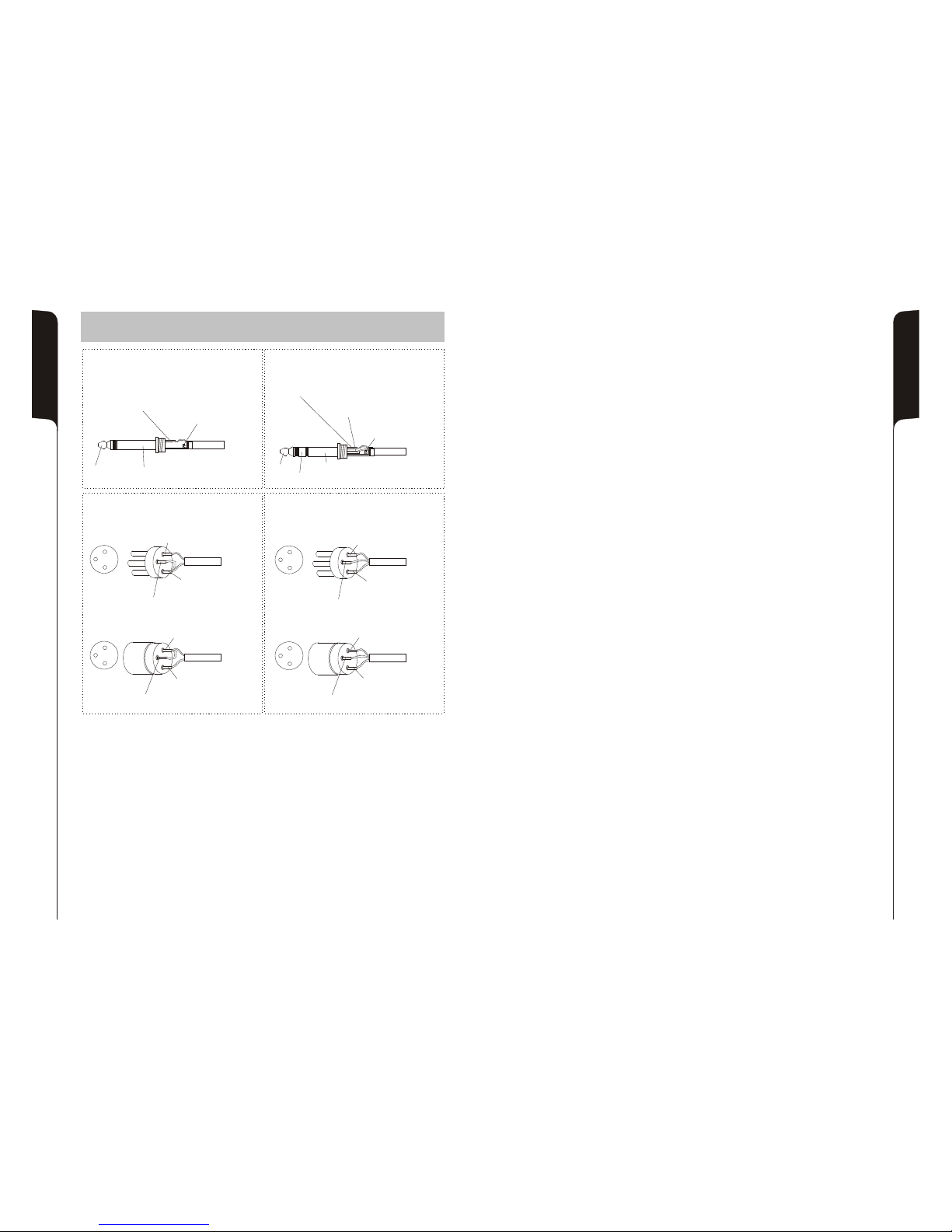
COLLEGAMENTI - CONNECTIONS
BRANCHEMENTSANSCHLÜSSE -
Tip
Sleeve
Tip = Signal
Sleeve=Screen/Ground/Earth
Unbalanced use of stereo 1/4” jack plug
Tip
Ring
Sleeve
Tip = Positive/Hot/+VE Phase
Ring=Negative/Cold/-VE Phase
Sleeve=Screen/Ground/Earth
Balanced use of stereo 1/4” jack plug
Balanced use with XLR connectors
Input
XLR - male
Pin 2 = Positive/Hot/+VE Phase
Pin 3 =Negative/Cold/-VE Phase
Pin 1 =Screen/Ground/Earth
Output
XLR - female
Pin 2 = Positive/Hot/+VE Phase
Pin 3 =Negative/Cold/-VE Phase
Pin 1 =Screen/Ground/Earth
Unbalanced use with XLR connectors
Input
XLR - male
Pin 2 = Positive/Hot/+VE Phase
Pin 1 =Screen/Ground/Earth
Output
XLR - female
Pin 2 = Positive/Hot/+VE Phase
Pin 1 =Screen/Ground/Earth
Pin 3 = Link to Pin 1
Pin 3 = Link to Pin 1
24
 Loading...