

Page 1

MODEL
4078
SINGLE-CHANNEL
AC STRAIN GAGE
INSTRUMENT
SB.2
INSTRUCTION MANUAL
4000
Instrument Series
Page 2

Copyright © 1996, Daytronic Corporation. All rights reserved.
No part of this document may be reprinted, reproduced, or used in any form or by
any electronic, mechanical, or other means, including photocopying and recording,
or in any information storage and retrieval system, without permission in writing
from Daytronic Corporation. All specifications are subject to change without notice.
Page 3

Model 4078 Instruction Manual, v. SB.2
Pub. No. 4078.2, Issued 10/96
MODEL
4078
SINGLE-CHANNEL
AC STRAIN GAGE INSTRUMENT
INSTRUCTION MANUAL
Part No. 91630
Daytronic Corporation
Dayton, OH 45439-1521
www.daytronic.com
Page 4

Page 5

1. Introduction
a. Description and Specifications ............................................. 1.1
b. Physical Layout .................................................................... 1.5
c. Panel Mounting .................................................................... 1.7
d. Standard Channel Configuration ..........................................1.8
e. Standard Logic Configuration .............................................. 1.9
f. Using the Front-Panel Setup Buttons ................................. 1.11
g. Low Battery Warning ..........................................................1.17
2. Setup
a. Transducer Cabling ............................................................. 2.1
b. Powerup .............................................................................. 2.5
c. Adjusting LCD Viewing Angle .............................................. 2.7
d. Selecting a Channel for Display .......................................... 2.8
e. Channel Calibration ............................................................. 2.9
f. Setting Channel Filter ........................................................ 2.12
g. Scaling the Bargraph Display ............................................ 2.13
h. Defining Limit Zones .......................................................... 2.15
i. Logic I/O Connections ....................................................... 2.16
j. Analog Output Connections ............................................... 2.18
3. Operation: Use of Front Panel Buttons ................................. 3.1
Appendix A: Complete Standard Configuration ......................... A.1
Appendix B: 4078/Computer RS-232-C Connections ............... B.1
Appendix C: Legend and Indicator Annunciation ....................... C.1
Appendix D: Modifying the Input Range .................................... D.1
Appendix E: Phase/Symmetry Adjustment for a
Lebow 1800 Series Transducer ................................................. E.1
Appendix F: "Simulated" Calibration ........................................... F.1
Appendix G: Changing the Battery ............................................ G.1
i
Contents
Section
Page
Page 6
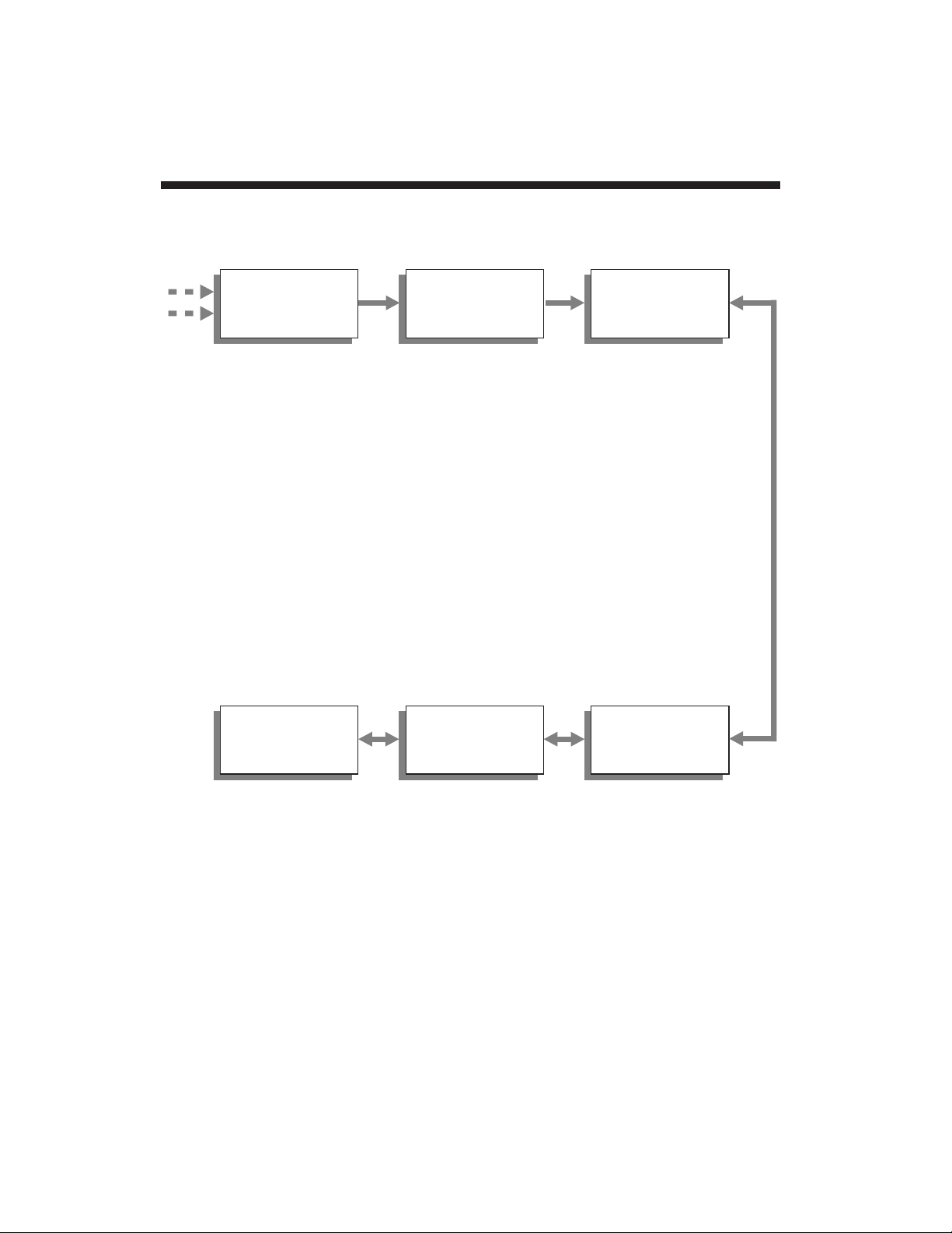
1.a Model 4078 Description and Specifications
1.1
A to D
Conversion
Real-Time
Math
Processing
Signal
Conditioning
Communi-
cations &
Memory
Process
Control
Displays &
Buttons
Transducer
Input(s)
General 4078 Features
• + – x ÷ √
• Digital Max/Min
• Constants
• Limits (7 zones,
including "Safety"; can
be used to generate
logic control outputs or
to trigger predefined
command sequences
automatically)
• Tare offset
• Scalable 51-segment
bargraph with endpoint indication
• Backlit 0.6-inch LCD
with adjustable viewing
angle and limittriggered flashing
• Independently settable
dual-limit displays
• RS-232-C I/O
• Port for optional
keyboard
• Simple step-through
configuration setup
and review via front
panel
• Battery-backed data
and configuration
storage
• Scalable 10-V analog
output for strip-chart
recording, etc.
• 8 TTL-level logic I/O's
for annunciation,
process control, and
automatic command
execution
• 16-bit (±32000 count)
• Optional internal
linearization (up to 15
variable-length
segments)
• Excitation
• "y = mx + b" scaling
• Analog and digital
filtering
Page 7

The Model 4078 is a single-channel conditioner of
phase-sensitive
carrier-amplifier
design (rather than a fully DC instrument). Intended for
applications involving transformer-coupling to the transducer bridge (as
with rotary-transformer torque sensors), it can also be used when high
sensitivity is required or where the electrical environment is especially
noisy. Responding only to the modulated carrier frequency, the 4078
rejects extraneous voltages that can cause errors in DC systems,
particularly when there is a need to "blow up" a portion of the transducer range.
A "tare" function is preprogrammed for the strain gage input, and may
be activated by a front-panel push button. Via front-panel buttons, you
can also display and reset MAXIMUM, MINIMUM, and "MAX minus
MIN" values for the "tared" analog input.
Unless otherwise specified at the time of order, your Model 4078 has
been set, prior to shipment, to a
standard configuration
. THIS
CONFIGURATION IS FULLY ADEQUATE FOR MOST APPLICATIONS, AND LETS YOU CONTROL BASIC INSTRUMENT SETUP
AND OPERATION SOLELY BY MEANS OF THE SIX FRONT-PANEL
PUSH BUTTONS. A full listing of your 4078's standard configuration is
given in Appendix A.
Like all 4000 Series instruments, however, the 4078 can be rapidly and
easily reprogrammed in the field, to provide a variety of unique
application solutions. For such reprogramming you can use either
• an optional Model 10P80D Extended Keyboard that plugs directly
into the rear of the 4078 unit, or
• the optional StartPAC 100 Software (Model GS-SP100).* This
software applies to ALL Daytronic RS-485 networkable instruments, and offers a number of valuable utilities for terminal
emulation, node configuration, network monitoring, data display
and logging, etc. IT IS SUPPLIED FREE OF CHARGE WITH ALL
4000 SERIES MODELS. For details on the installation and
operation of StartPAC 100, see the
StartPAC 100 Instruction
Manual
.
StartPAC 100 lets a connected computer serve as a "dumb" terminal
for entry of the specific MNEMONIC COMMANDS required to repro-
1.2
Model 4078 Description and Specifications 1.a
* Alternatively, you can use any of a number of commercially available
terminal emulation programs
to issue commands directly to the 4078.
Page 8

gram the 4078. These commands may also be issued directly to the
4078 via the optional Extended Keyboard. Commands which are
common to all 4000 Series models are described in detail in the
optional 4000 Series
System Instruction Manual
. IT IS RECOM-
MENDED THAT YOU STUDY THE
SYSTEM INSTRUCTION
MANUAL
BEFORE YOU ATTEMPT ANY RECONFIGURATION OF
YOUR MODEL 4078 BEYOND THAT DISCUSSED IN THE
APPENDICES OF THE PRESENT MANUAL.
See Appendix B of the present manual for direct RS-232-C connections
between the 4078 and a computer or printer.
Unless otherwise specified, every 4078 comes with the standard
engineering-unit legends
and
button-function indicators
shown in Fig. 1.
Different legend/indicator films may be optionally obtained. Via optional
keyboard or computer, you can instruct the 4078 to light any one or a
combination of given legends and indicators. See Appendix C for
"Legend and Indicator Annunciation." Note that under the "standard
configuration," the "F1" indicator will
always
be on when the 4078 is in
"RUN-TIME" mode.
Your 4078 is initially configured for a full-scale transducer range of
3.00 mV/V
(excitation for the 4078 is
fixed
at 3 V-AC RMS). If you
require a range setting of 0.75 or 1.50 mV/V, see Appendix D. Appendix F explains an alternative "simulated calibration" technique that uses
an internal shunt resistor and requires the entry of special mnemonic
commands to open and close the shunt (via computer or keyboard).
NOTE: EXCEPT FOR APPENDICES C, D, AND F—AND ALSO THE
PHASE AND SYMMETRY ADJUSTMENT
PROCEDURES GIVEN IN
SECTION 2.e AND APPENDIX E—THE PRESENT MANUAL WILL
ONLY TREAT PROCEDURES AND CONSIDERATIONS WHICH ARE
RELEVANT TO THE 4078 "STANDARD CONFIGURATION" AND
WHICH DO NOT REQUIRE A CONNECTED COMPUTER OR
KEYBOARD. FOR INFORMATION ON THE FULL FUNCTIONALITY
OF YOUR MODEL 4078, SEE THE OPTIONAL
SYSTEM
INSTRUCTION MANUAL
.
MODEL 4078 SPECIFICATIONS (for general 4000 Series Physical,
Electrical, and Environmental specifications—including Logic
1.a Model 4078 Description and Specifications
1.3
Page 9

I/O—see Appendix A of the 4000 Series
System Instruction
Manual)
:
Transducer Types and Ranges: The 4078 accepts a force-
measurement signal from a conventional strain gage transducer
with 4-arm bridge of nominal 350 ohms or higher, and a full scale
range of 0.75, 1.50, or 3.00 mV/V.
Excitation: Regulated 3 V-AC (rms) at 3280 Hz; 75 mA (rms),
maximum
Amplifier: AC-coupled demodulator with user-settable phase and
symmetry controls
Normal-Mode Range: ±12 mV rms, operating; ±8 V-DC without
instrument damage
Common-Mode Range: ±0.8 V-DC operating; ±8 V-DC without
instrument damage
Common-Mode Rejection Ratio: DC: infinite; at 60 Hz: infinite; at 1
kHz: -80 dB; at 3 kHz: -60 dB
Input Impedance (Differential and Common-Mode): 10 megohms
Offset: Initial: ±3% of full scale; vs. temperature: ±0.005% f.s./°C; vs.
time: ±0.002% f.s./month
Gain Accuracy*: ±0.025% of full scale
typical
, following calibration
Gain Stability: vs. temperature: ±50 ppm/°C; vs. time: ±20
ppm/month
Filter: 3-pole modified Butterworth; 3 dB down at 7.5 Hz; 60 dB down at
60 Hz
Step Response Settling Time (Full-Scale Output):
To 1% of final value: 300 msec
To 0.1% of final value: 450 msec
To 0.02% of final value: 600 msec
Analog Output: ±10 V, microprocessor driven and scaled, ±1 mV
resolution
Accuracy: 0.05% of current voltage reading ± 2 mV
Output Bandwidth: 40 Hz maximum
* Initial (uncalibrated) inaccuracy may be as great as ±3% of full scale.
Maximum error that could occur upon replacement of a Model 4078
not followed by calibration
is ±6% of full scale.
1.4
Model 4078 Description and Specifications 1.a
Page 10
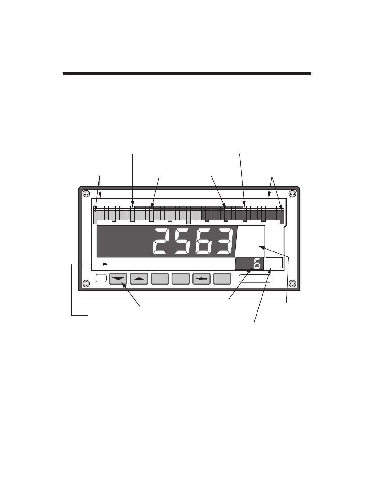
Study the following diagrams to acquaint yourself with your 4078's most
important front and rear elements.
1.b Physical Layout
1.5
psi
lb-ft
Bargraph
Low Endpoint
(LEP)
"Low-Low" Limit
(LLL)
Setup and Special
Function Buttons
Engineering-
Unit Legends*
Channel No.
and
Mnemonic
Display
lbs
SET
UP
Bargraph
High Endpoint
(HEP)
"High-High" Limit
(HHL)
"Low" Limit
(LOL)
"High" Limit
(HIL)
Button
"RUN-TIME
FUNCTION"
Indicators*
Button Activity
Indicator
ON
LINE
F1 F2 F4
SET
UP
F3 F5
* Standard film shown.
(F1 = LIVE DISPLAY
F2 = [NOT USED]
F3 = TARE
F4 = MAX/MIN/MAX-MIN STEP
F5 = MAX/MIN RESET
—see Section 3)
CHAN STEP
44000
Fig. 1 4078 Front Panel
Page 11
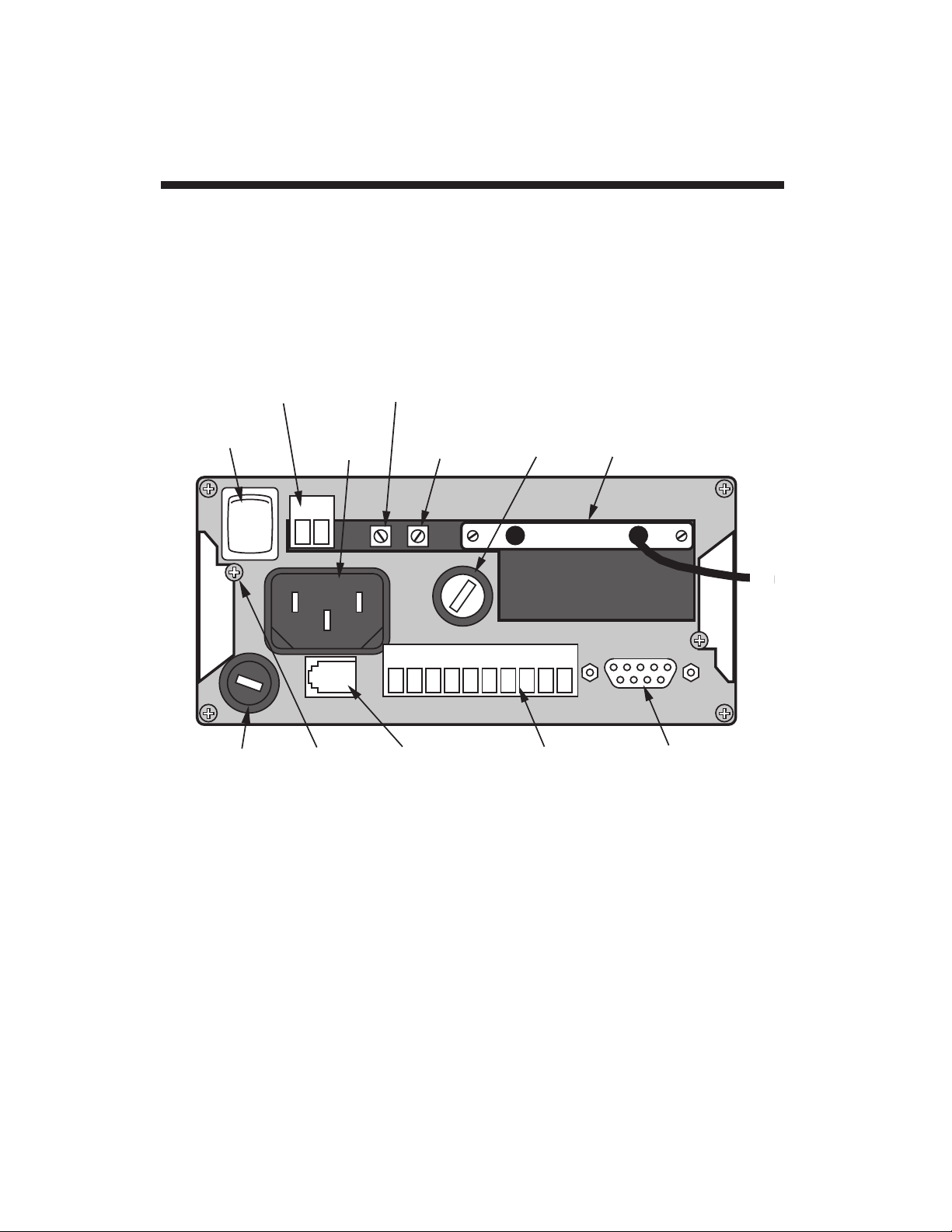
Physical Layout 1.b
1.6
Analog
Output
Connector
(see Fig. 10)
1
O
CONDITIONER
CONNECTOR
—attaches to 4078
Analog Input Board
(see Figs. 5-7)
Logic I/O
Connector
(see Figs. 4, 9)
ON-OFF
Switch
Fuse
AC Power
Connector
Connector
for Optional
Keyboard
Voltage
Selector
Switch
RS-232-C
Interface
Connector
(see App. B)
PanelMount
Clamp
Screw
PHASE
ADJUSTMENT
CONTROL
SYMMETRY
ADJUSTMENT
CONTROL
Fig. 2 4078 Rear Panel
Page 12
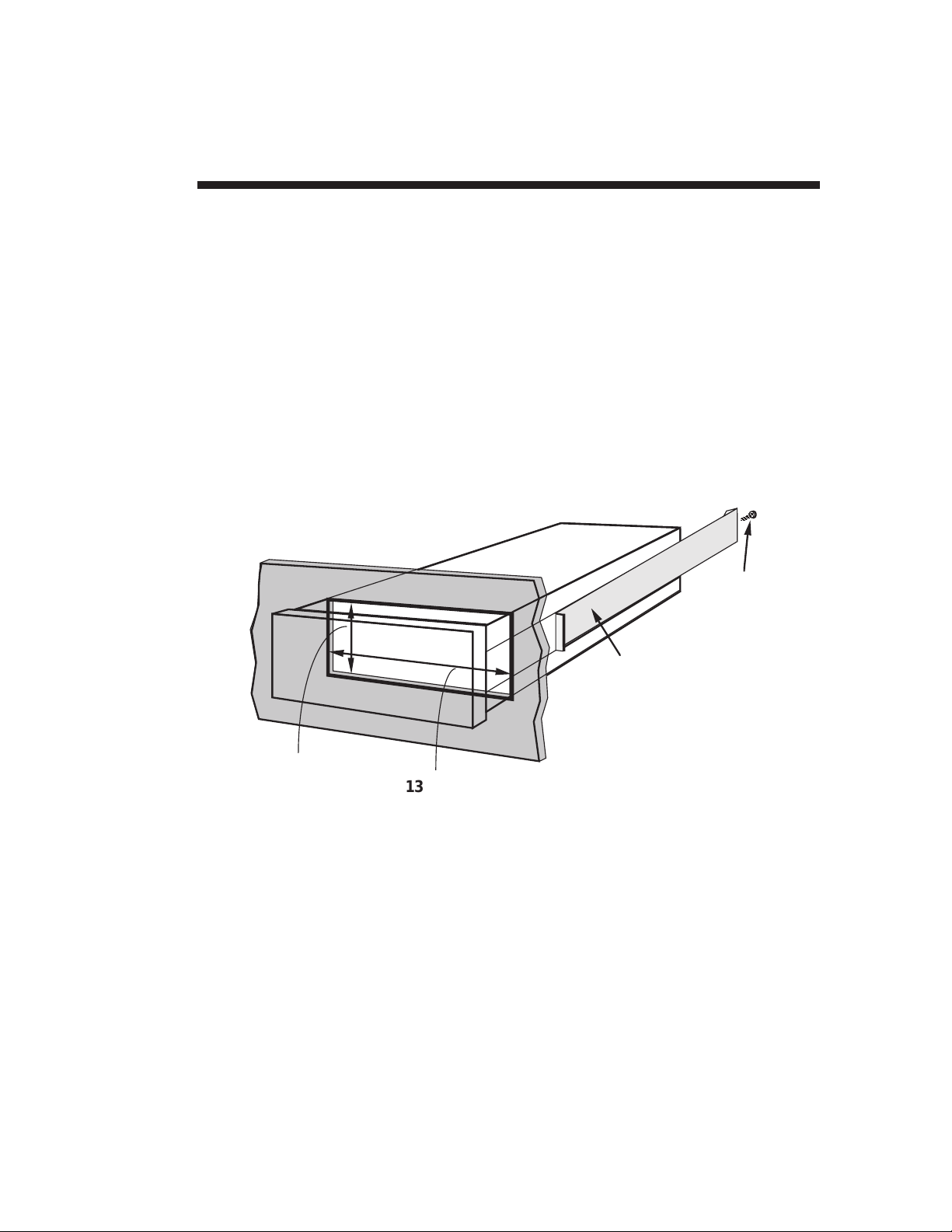
You can easily mount a Model 4078 in your own precut panel. Cutout
dimensions for a
panel-mounted
unit are standard DIN (see Fig. 3);
panel thickness should not exceed 6 mm (0.24 in).
When mounting a 4078,
DO NOT REMOVE THE FRONT BEZEL.
Simply unscrew the two rear-panel CLAMP SCREWS and slide the
CLAMP SLIDES rearwards out of their grooves. Insert the 4078 unit
through the panel cutout,
from the front of the panel
(if the unit has
rubber feet, these will have to be removed). Then reinstall the CLAMP
SLIDES, and tighten the CLAMP SCREWS until the instrument is
securely mounted.
1.7
1.c Panel Mounting
138 ± 1.0 mm
(5.43 ± 0.04 in)
68 ± 0.7 mm
(2.68 ± 0.03 in)
CLAMP SLIDE
CLAMP
SCREW
Fig. 3
4078 Panel Mounting
Page 13

Channel No. Channel Function
1 "LIVE" INPUT CHANNEL
This channel represents the 4078's
conditioned analog
input
. Sensor calibration is performed on this channel, as
explained in Section 2.e and Appendix F.
2 THIS CHANNEL IS NOT T
O BE USED FOR THE 4078
5 "LIVE" INPUT WITH TARE
This channel represents the value of Channel 1
minus
the current "tare" offset for the input
(that is, the value of
Channel 1 that existed when the front-panel "TARE"
button was last pressed). Active control limits will
normally operate on the basis of this channel—see
Section 1.e.
6 "MAXIMUM" VALUE OF CHN. 5
This channel represents the
most positive
value of
Channel 5 since "MAX" measurement was last reset via
the front-panel "MAX/MIN RESET" button.
7 "MINIMUM" VALUE OF CHN. 5
This channel represents the
least positive
value of
Channel 5 since "MIN" measurement was last reset via
the front-panel "MAX/MIN RESET" button.
8 "MAX minus MIN" VALUE OF CHN. 5
This channel represents the existing
net difference
between Channel 6 and Channel 7.
19 ANALOG OUTPUT
This channel represents Channel 5 ("tared" analog input),
scaled to a full range of ± 10 V-DC. It may be used for
strip-chart recording, input to other systems, or generalpurpose signal monitoring. For rescaling and connection
of the analog output, see Section 2.j.
The 4078's Channel Nos. 4 and 14-16 are used as intermediate result
registers or reference channels, and will not normally be displayed.
The remaining scanned channels (Nos. 2, 3, 9-13, 17, and 18) are not
used in the standard 4078 configuration. CHANNEL 2 CANNOT BE
USED IN
ANY
4078 CONFIGURATION.
Standard Channel Configuration 1.d
1.8
Page 14
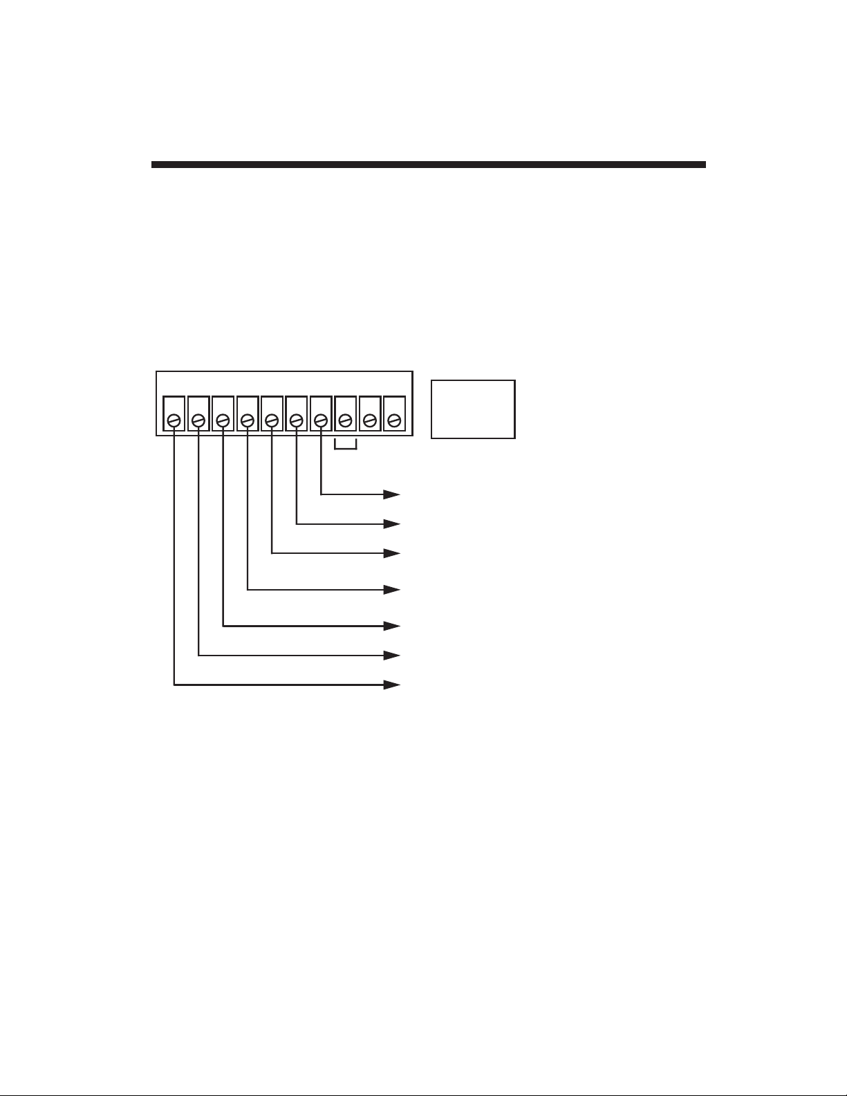
Your 4078 provides eight logic input/output bits in
open-collector,
negative-true
form, where the "Logic 1" state is defined as nominal
0
V-DC
and "Logic 0" as nominal
+5 V-DC.
The standard logic I/O
configuration is shown in Fig. 4, below, with reference to the 10-terminal
Logic I/O Connector on the rear of the 4078. For recommended logic
interconnections, see Section 2.i.
You can use the seven logic control outputs to actuate solenoid valves,
illuminate panel displays, sound alarms, start and stop motors or
pumps, initiate and control safety shut-down sequences, and perform
many other automation tasks that require "intelligent" switching, even of
substantial amounts of power. These are
nonlatching
outputs; each
terminal will return to
Logic 0
as soon as the corresponding limit
violation ceases to occur. For "Defining Limit Zones," see Section 2.h.
1.e Standard Logic Configuration
1.9
0 1 2 3 4 5 6 7 +5 GD
LOGIC LOW
TO ENABLE
(see Fig. 9)
Unassigned
CHN. 5 IN "ABOVE BARGRAPH" ZONE
CHN. 5 IN UPPER "DANGER" ZONE
CHN. 5 IN UPPER "CAUTION" ZONE
Logic Outputs:
CHN. 5 IN SAFETY (NO VIO) ZONE
CHN. 5 IN LOWER "CAUTION" ZONE
CHN. 5 IN LOWER "DANGER" ZONE
CHN. 5 IN "BELOW BARGRAPH" ZONE
Fig. 4 4078 Standard Logic Outputs
Page 15

Bit No. Logic Function
0 "BELOW BARGRAPH" VIOLATION OUTPUT
Terminal 0 will be at a
Logic 1
(0 V-DC) level whenever
the reading of Channel 5 is less than the current "LEP"
value for that channel.
1 "LOW LOW" VIOLATION OUTPUT
Terminal 1 will be at a
Logic 1
(0 V-DC) level whenever
the reading of Channel 5 is less than the current "LLL"
value for that channel and greater than or equal to the
current "LEP" value.
2 "LOW" VIOLATION OUTPUT
Terminal 2 will be at a
Logic 1
(0 V-DC) level whenever
the reading of Channel 5 is less than the current "LOL"
value for that channel and greater than or equal to the
current "LLL" value.
3 "OK" (NO VIOLATION) OUTPUT
Terminal 3 will be at a
Logic 1
(0 V-DC) level whenever
the reading of Channel 5 is greater than or equal to the
current "LOL" limit value and less than or equal to the
current "HIL" limit value for that channel.
4 "HIGH" VIOLATION OUTPUT
Terminal 4 will be at a
Logic 1
(0 V-DC) level whenever
the reading of Channel 5 is greater than the current "HIL"
value for that channel and less than or equal to the
current "HHH" value.
5 "HIGH HIGH" VIOLATION OUTPUT
Terminal 5 will be at a
Logic 1
(0 V-DC) level whenever
the reading of Channel 5 is greater than the current
"HHH" value for that channel and less than or equal to
the current "HEP" value.
6 "ABOVE BARGRAPH" VIOLATION OUTPUT
Terminal 6 will be at a
Logic 1
(0 V-DC) level whenever
the reading of Channel 5 is greater than the current
"HEP" value for that channel.
1.10
Standard Logic Configuration 1.e
Page 16

Study this manual section carefully to familiarize yourself with the
general operation of your 4078's front-panel buttons when they are in
"SETUP" mode. Specific setup parameters—such as "HIGH ENDPOINT (HEP)", "FILTER (FIL)," "LCD," etc.—are explained in detail in
Section 2.
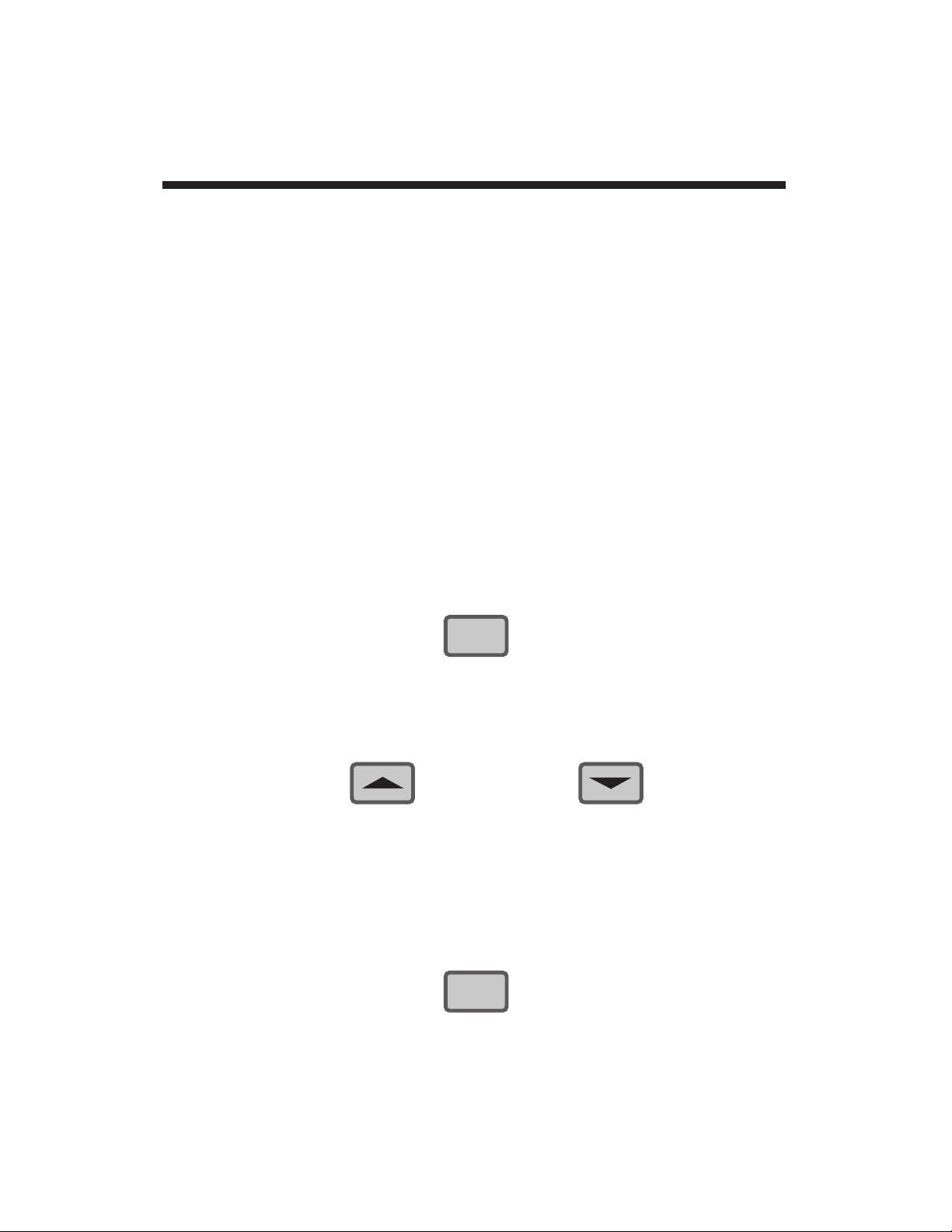
The 4078 provides
instant visual feedback
for its front-panel buttons.
Thus, pressing any button will light the green ON LINE indicator. This
indicator is located in the lower right-hand corner of the 4078 front
panel (see Fig. 1). It will remain lit as long as the button is pressed.
The 4078's six front-panel buttons greatly simplify the basic setup
procedure. With them you can quickly review in sequence the existing
numeric "configuration parameters"
of any selected channel. At the
same time you can easily reset any displayed parameter to any
allowable value. The LEFT ARROW button lets you select a displayed
digit
or
decimal-point location.
The UP ARROW and DOWN ARROW
buttons let you change as desired the numeric value of the parameter,
its polarity, and/or (if it is a calibration value) its decimal-point location.
The new number goes into effect as soon as you exit "SETUP," and is
automatically stored in battery-backed memory.
1. Entering "Setup" Mode
To enter "SETUP" mode,
PRESS THE BUTTON
WARNING!
DO NOT USE A SHARP OR POINTED OBJECT TO
DEPRESS THE FRONT-PANEL BUTTONS.
SERIOUS INSTRUMENT DAMAGE COULD RESULT.
ALSO, DO NOT SPLASH LIQUID ON THE FRONT
OF THE UNIT. THIS CAN CAUSE THE BUTTON
SWITCHES TO SHORT OUT.
1.f Using the Front-Panel Setup Buttons
1.11
SET
UP
Page 17
Each of the six buttons will now assume its "SETUP" function, as
designated by the actual button label (for each button's "RUNTIME" function, see Section 3.) The small mnemonic display under
the 4078's unit legends will alternately read "DIS" and the number
of the channel that was on display when you pushed the SETUP
button. The main LCD display will read the number of the currently
selected channel. The rightmost digit of the main LCD display will
now flash, indicating that it is the "active" digit. NOTE: the smaller
display will continue to read the number of the
initially selected
channel—even though you may call one or more other channels to
the main display during the setup procedure—and will alternate
this number with the
mnemonic
of the parameter presently under
consideration. On exiting "SETUP," the smaller display will show
the number of the channel currently displayed by the main LCD.
2. Selecting a Channel for Setup and/or Review
If, after pressing SETUP, you wish to review and/or reconfigure the
channel whose number is now being displayed,
PRESS THE BUTTON
This will invoke the channel's actual "parameter list," beginning
with "LCT."
If this is
not
the channel you wish to review and/or reconfigure,
PRESS THE BUTTON OR THE BUTTON
one or more times until you arrive at the desired channel. Then
press the STEP button to invoke its parameter list. When you exit
"SETUP" mode, the last channel to have been thus selected will
continue to be displayed.
At any time during the setup procedure, you can move back up to
the "DIS" parameter of the channel currently on display. Simply
PRESS THE BUTTON
1.12
Using the Front-Panel Setup Buttons 1.f
STEP
CHAN
Page 18

—at which point you can, if desired, move to any other channel via
the UP/DOWN ARROW buttons, as above.
3. Stepping Through a Channel's Parameter List
A given channel's configuration sequence includes the parameters
listed on the next page. These will appear as mnemonics under
the unit-legend display. Their respective
numeric values
will
appear on the main LCD digital display. ONLY THE PARAMETERS PRINTED IN BOLDFACE ARE TREATED IN THIS
MANUAL. For the remaining parameters, see the optional
System
Instruction Manual.
Channel Configuration Parameters
DIS (DISPLAY) (Section 2.d)
LCT (LOCATE)
LNS (LINEARIZATION SEGMENTS)
F0 (FIRST CALIBRATION POINT) (Section 2.e)
F1* (SECOND CALIBRATION POINT) (Section 2.e)
LEP (LOW ENDPOINT) (Section 2.g)
LLL (LOW LOW LIMIT) (Section 2.h)
LOL (LOW LIMIT) (Section 2.h)
HIL (HIGH LIMIT) (Section 2.h)
HHL (HIGH HIGH LIMIT) (Section 2.h)
HEP (HIGH ENDPOINT) (Section 2.g)
ASN (ASSIGN SATELLITE NUMBER)
FIL (FILTER) (Section 2.f)
BAU (BAUD RATE)
DBS (DATA BITS)
SBS (STOP BITS)
PAR (PARITY)
LCD (LCD VIEWING ANGLE) (Section 2.c)
REL (4000 SOFTWARE RELEASE DATE)
1.f Using the Front-Panel Setup Buttons
* Applicable only to 4078 Channel 1.
1.13
Page 19

To move to the next parameter in sequence,
PRESS THE BUTTON
As each parameter appears, you have the option of leaving it as it
is and stepping to the next one by again pressing STEP, or of
modifying its value by means of the "ARROW" buttons. You
cannot backstep through the parameter sequence; you can only
start it over again, via the CHAN button, or continue stepping
forward until you come back around to the desired parameter.
4. Moving the "Active" Digit
As each parameter value appears on the LCD display, its least
significant digit will be
flashing
, to signify that this is the currently
"active" (changeable) digit. You have the option of changing the
value of the "active" digit, as explained in Step 5, or of "activating"
the next digit to the left. To move the "active" digit one digit to the
left,
PRESS THE BUTTON
For "activation" of
decimal points
, see Step 7, below.
NOTE: You cannot move the active digit to the right. If you want to
return to a digit you have already passed, you must continue
moving leftward until you come back around to the desired digit.
5. Modifying the "Active" Digit
To increase the value of the active digit by "1"—that is, to add "+1"
to that number, regardless of its algebraic sign—
PRESS THE BUTTON
To decrease the value of the active digit by "1"—that is, to add "-1"
to that number, regardless of its sign—
PRESS THE BUTTON
1.14
Using the Front-Panel Setup Buttons 1.f
STEP
Page 20

In the negative realm
, these buttons seem at first glance to function
backwards. Thus, if the displayed parameter is preceded by a
minus sign, then "increasing" the active digit by "1"—as a result of
pressing the UP ARROW button—means
decreasing
that digit's
absolute value
by "1." Similarly, by pressing the DOWN ARROW
button you will cause the absolute value of a negative active digit
to
increase
by "1." When dealing with negative parameters, just
remember that the UP ARROW button brings you UP the number
scale towards zero, through progressively "lower" (more positive)
negative numbers, while the DOWN ARROW takes you DOWN the
scale through progressively "higher" negative numbers.
You can cycle a given active digit—positive or negative—in either
direction. With the completion of every "upward" cycle (either a
positive
active digit going from"9" back to "0" or a
negative
one
going from "0" back to "9"), "+1" will be added to that digit, with
appropriate adjustment of higher-placed digits. For example, if the
originally displayed number is "99
0" (the active digit being the
second from the right), and the UP ARROW button is pressed
once, the resulting number will be "100
0." Note that the original
active digit will continue to flash until you press the LEFT ARROW
button.
Similarly, after every "downward" cycle (either a
positive
active digit
going from"0" back to "9" or a
negative
one going from "9" back to
"0"), "-1" will be added to that digit, with appropriate adjustment of
higher-placed digits (e.g., "-19
20" becomes "-2020" when the
active digit is the third from the right and the DOWN ARROW is
pressed once).
6. Modifying the Polarity of the Displayed Value
To change the polarity of the presently displayed number, press the
LEFT ARROW button repeatedly until the
leftmost
digit (the "most
significant digit") is active. Cycle this digit once
through zero
and
back to its original numeric value. If you're changing the number
from
positive to negative
, you will cycle "downwards" through zero
via the DOWN ARROW button; if you're changing from
negative
to positive
, you will cycle "upwards" through zero via the UP
ARROW button. The number's sign will change as the most
significant digit passes through zero.
1.f Using the Front-Panel Setup Buttons
1.15
Page 21

NOTE: The above procedure
will change the original values of
one or more digits to the right of the most significant digit
, except in
the case where they are all originally zero. Therefore, you will
most likely have to go back and
reset
these digits, using the LEFT
ARROW and UP/DOWN ARROW buttons as explained in Step 5.
7. Adding a Decimal Point or Modifying the Decimal-Point
Location
NOTE: You can only add or modify a decimal point for an "F0" or
"F1" entry (see Section 2.e). Decimal points may appear in the
limit-zone parameters ("LEP," "LLL," "LOL," etc.) following
calibration, but
these cannot then be modified
.
To add a decimal point to an existing integral "F0" or "F1" value,
press the LEFT ARROW button repeatedly until five flashing
decimal points appear. Then press the UP ARROW button
repeatedly until a single flashing decimal point appears in the
desired position (the DOWN ARROW button can here be used to
move the decimal point to the right, if necessary).
To change the position of an existing decimal point, press the
LEFT ARROW button repeatedly until the present decimal point is
"active." To move it to the left, press the UP ARROW button; to
move it to the right, press the DOWN ARROW button.
NOTE: Decimal-point modification of the "F0" setting will not be
effective until the "F1" setting has been similarly modified. If the
"F1" decimal point is initially in the desired location, it is still
necessary to "relocate" it. Move the "F1" decimal point first to
some other location, and then back to its original location.
8. Exiting "Setup" Mode
To exit "SETUP" mode at any time during the above procedure,
PRESS THE BUTTON
All configuration changes will be saved, and all front-panel buttons
will resume the normal "RUN-TIME" functions described in Section
3.
1.16
Using the Front-Panel Setup Buttons 1.f
SET
UP
Page 22

The 4078 is equipped with an internal 3-V lithium battery. This battery
is necessary to maintain the instrument's DATA RAM and to retain
factory-entered analog alignment values required for accurate
calibration. Data retention is guaranteed down to a battery level of 2.2
V-DC. Under normal usage, the battery should last about five years.
The 4078 will check its battery every time the unit is turned on. If on
powerup, the battery is found to be below 3.0 V-DC, the front-panel
LCD will display a warning of "LO bat." Note that at this level the
battery will still be good for weeks or even months. You are advised,
however, to
change the battery
as soon as possible after the warning
first appears. Detailed instructions for this procedure are given in
Appendix G of this manual.
To acknowledge the "LO bat" warning and resume the normal display,
simply press any one of the front-panel buttons.
1.17
1.g Low Battery Warning
Page 23

The Model 4078's Analog Input Board mates with Daytronic CONDITIONER CONNECTOR No. 60322, which allows direct
solder-terminal
attachment of cable leads. The connector's internal solder terminals
are labelled 1 through 10 and A through L. The connector is "keyed" by
small plastic inserts embedded between certain terminal-pin pairs, each
of which matches a slot in the 4078's rear Analog Input Board. This
prevents the connector from being inadvertently attached upside-down.
Open the connector housing by removing the four screws that hold it
together. Secure all cables by means of the internal clamp bars.
4-wire strain gage cabling (Fig. 5(a)) is to be used when the cable is
under 20 feet in length.
The 4078 is equipped with an internal 59-KΩ, 0.1%
calibration resistor
for the standard "shunt" calibration technique described in Appendix F.
If you wish to use your own external shunt resistor, it should be tied
between Pin 5 of the CONDITIONER CONNECTOR and the transducer's +SIGNAL line, as shown in Fig. 6. In this case, "CAL SENSE"
(Pin 4) is not used.
With cabling under 20 feet in length, the +SENSE and –SENSE lines
are tied to the corresponding EXCITATION lines
at the CONDITIONER
CONNECTOR.
Also, the CALIBRATION SENSE line from Pin 4—or
2.1
Transducer Cabling 2.a
---------- IMPORTANT----------
CABLE SIGNAL WIRES SHOULD ALWAYS BE PROPERLY
SHIELDED
, AS INDICATED IN THE DIAGRAMS BELOW. THIS
WILL MINIMIZE THE PRODUCTION OF UNWANTED ELECTRICAL NOISE FROM CAPACITIVE AND INDUCTIVE EFFECTS.
THE "SHIELD" WIRE OF EACH TRANSDUCER CABLE
SHOULD BE SOLDERED TO THE EXPOSED TERMINAL OF
THE L-SHAPED GROUND LUG LOCATED UNDER THE HEAD
OF ONE OF THE CONNECTOR'S TWO CAPTIVE MOUNTING
SCREWS. THIS WILL ENSURE DIRECT SHIELD CONTACT
WITH THE 4078 CASE.
Page 24

the optional external SHUNT RESISTOR line from Pin 5—is tied to the
+SIGNAL line
at the CONDITIONER CONNECTOR.
8-wire strain gage cabling (Fig. 5(b)) is to be used when the cable is 20
feet or longer.* As before, you can install your own shunt calibration
resistor between Pin 5 and the +SIGNAL line, in which case Pin 4 is not
used.
With cabling of 20 feet or over, the +SENSE and –SENSE lines are tied
to the corresponding EXCITATION lines
at the transducer
. Also, the
CALIBRATION SENSE line from Pin 4—or the optional external
SHUNT RESISTOR line from Pin 5—is tied to the +SIGNAL line
at the
transducer
. Note the wire connected to the –SIGNAL line at the trans-
ducer, but left
unconnected
at the 4078. This wire is to be paired with
the CAL SENSE or SHUNT RESISTOR line for shielding purposes.
Special 8-wire cabling (shown in Fig. 7) is required for connecting a
Model 4078 to a Lebow 1600 Series Transducer. The cable should
2.a Transducer Cabling
* NOTE: This cabling is to be used when connecting a Model 4078 to a Lebow
1800 Series Transducer.
2.2
A
B
C
D
E
F
H
J
K
L
1
2
3
4
5
6
7
8
9
10
+SIGNAL
CONDITIONER CONNECTOR
(No. 60322)
–EXCITATION
+EXCITATION
–SIGNAL
–SENSE
+SENSE
CAL SENSE
SHIELD
Connector pins shown as viewed
from rear (cable) side of connector.
Ground Lug
Fig. 5(a)
Model 4078
Transducer Cabling:
4-Wire Strain Gage Cabling
(under 20 ft. in length)
Page 25

2.3
Transducer Cabling 2.a
A
B
C
D
E
F
H
J
K
L
1
2
3
4
5
6
7
8
9
10
CONDITIONER CONNECTOR
(No. 60322)
–SENSE
+SENSE
SHIELD
External
SHUNT
CALIBRATION
RESISTOR
(UserSupplied)
+SIGNAL
Fig. 6
Model 4078
Transducer Cabling:
Installation of User's
External Shunt
Calibration Resistor
A
B
C
D
E
F
H
J
K
L
1
2
3
4
5
6
7
8
9
10
CONDITIONER CONNECTOR
(No. 60322)
+EXCITATION
+SENSE
SHIELD
Connector pins shown as viewed
from rear (cable) side of connector.
Ground Lug
+SIGNAL
–EXCITATION
–SIGNAL
–SENSE
CAL SENSE
Unconnected wire
(Paired with "CAL SENSE")
Fig. 5(b)
Model 4078 Transducer
Cabling: 8-Wire Strain
Gage Cabling (20 ft. or
longer)
Page 26

be shielded in four pairs, as shown in the figure, with the shield open at
the transducer end. Also note that
• SENSE and EXCITATION lines should be tied
at the transducer
.
• The 4078's Pin 5 ("LEBOW CAL") is to be connected to the "CAL"
pin on the Lebow sensor (Pin 4 is not used in this case).
• Leave the last (extra) wire unconnected at both ends, and pair it
with the "LEBOW CAL" line for the fourth shield.
• THE MODEL 4078 MUST BE INTERNALLY SET TO "SIGNAL
COMMON" MODE. CONTACT THE FACTORY FOR PRECISE
INSTRUCTIONS.
2.a Transducer Cabling
2.4
A
B
C
D
E
F
H
J
K
L
1
2
3
4
5
6
7
8
9
10
CONDITIONER CONNECTOR
(No. 60322)
+EXCITATION
+SENSE
SHIELD
Connector pins shown as viewed
from rear (cable) side of connector.
Ground Lug
+SIGNAL
–EXCITATION
–SIGNAL
–SENSE
A
D
C
B
CAL
(E)
Unconnected wire
(Paired with "LEBOW CAL")
LEBOW CAL
Fig. 7
Model 4078 Transducer Cabling:
8-Wire Cabling to LEBOW 1600 SERIES TRANSDUCER (ONLY)
Page 27

A 4078 can operate from a line voltage of either 90-135 or 180-270 VAC (47-63 Hz; 35 W maximum). The VOLTAGE SELECTOR SWITCH
is located on the rear panel (see Fig. 2).
If you change the voltage-level setting, YOU MUST ALSO CHANGE
THE 4078'S BUSS FUSE (again, see Fig. 2): nominal 110 V-AC takes a
0.5-amp fuse; nominal 220 V-AC takes a 0.25-amp fuse.
To change the fuse after changing the voltage setting—or after the
existing fuse has "blown" for some reason—use a screwdriver to turn
the fuse slot counterclockwise, and the fuse will spring out.
IN THE EVENT OF AN APPARENT POWER-SUPPLY FAILURE,
FIRST CHECK THE FUSE. WHEN REPLACING A "BLOWN" FUSE,
ALWAYS INVESTIGATE THE CAUSE OF OVERLOAD BEFORE
REACTIVATING THE INSTRUMENT.
The 7.5-foot, three-conductor power cord supplied with the 4078 plugs
into the rear AC POWER CONNECTOR. The offset pin on the power
Powerup 2.b
2.5
---------- PLEASE NOTE ----------
EVERY TIME YOU POWERUP YOUR MODEL 4078, ALLOW A
NOMINAL 15 SECONDS FOR VALID DATA AND SETUP
VALUES TO BE ESTABLISHED.
ALSO NOTE: Since setup entries are automatically saved to
nonvolatile memory, your 4078 will always powerup to the
same setup and display configuration that existed when it was
last powered down.
---------- IMPORTANT ----------
Before powering up your 4078, make sure that the VOLTAGE
SELECTOR SWITCH is set to the proper nominal AC line
voltage (110 or 220).
Page 28

connector is ground. THE INSTRUMENT MUST BE PROPERLY
GROUNDED. To safely operate from a
two-contact
outlet, use a 3prong-to-2-prong adaptor and connect the green pigtail on the adaptor
to earth ground.
Since the presence of
electrical noise
can affect the ultimate integrity of
your data, the noise level should be suppressed as much as possible.
In particular, care should be taken to avoid utility-line problems that can
interfere with or possibly even damage sensitive microprocessor-based
equipment. Such noise can also be generated by electrical motors,
relays, and motor control devices.
While your 4078 has internal circuitry to protect it from overvoltage
transients and mild EMI, a clean line is still very desirable. No
protection is provided against dropout longer than 8 milliseconds or
brownout below 90 volts. Depending on your line conditions, a number
of protective devices are available (isolators, regulators, uninterruptible
power supplies, etc.).
2.6
2.b Powerup
Page 29

You can easily optimize your 4078's LCD DIGITAL DISPLAY for your
particular
viewing angle
.
1. Following the procedure given in Section 1.f, above, press the
instrument's front-panel SETUP key, and then "step" to the "LCD"
parameter (the letters "LCd" should appear in the digital display, to
indicate that the instrument is in "LCD adjustment" mode).
2. If you wish to
raise
the viewing angle—that is, to make the display
more readable from
above
the instrument—press the "UP
ARROW" key until the desired display of the word "LCd" is produced (note that the extreme setting in this direction will cause the
display to disappear, and you will then have to lower the angle
somewhat (Step 3)). Also note that it usually takes about three
seconds before you see any real change in the display.
3. If you wish to
lower
the viewing angle—that is, to make the display
more readable from
below
the instrument—press the "DOWN
ARROW" key until the desired display of the word "LCd" is
produced (note that the extreme setting in this direction will cause
all segments of the display to be clearly visible when the instrument is viewed from any angle except approximately 30% below
the level of the display).
4. To return the display to "normal" mode, press the SETUP key once
again. The 4078 should subsequently powerup with the LCD angle
to which you have just set it.
2.7
Adjusting LCD Viewing Angle 2.c
Page 30

Your 4078's "Standard Channel Configuration" was given in Section
1.d, above. To cause the current "live" reading of any channel—either
"scanned" or "unscanned"—to be displayed on both the DIGITAL and
BARGRAPH displays, you need only
1.
PRESS THE BUTTON
2.
PRESS THE BUTTON OR THE BUTTON
repeatedly until the number of the desired channel appears in the
main
LCD display (the original channel number will continue to
flash in the small mnemonic display under the engineering
legends).
3. Again
PRESS THE BUTTON
The number of the displayed channel should now appear in the
mnemonic display, with the "live" reading of this channel in the
main LCD display.
NOTE: As explained in Section 3, you can always use the LIVE
DISPLAY button—when not in "SETUP MODE"—to call to display your
4078's Channel 5 ("tared" analog input). You can also use the
MAX/MIN/MAX-MIN STEP button to cycle sequentially through
Channel 5 through 8.
2.d Selecting a Channel for Display
2.8
SET
UP
SET
UP
Page 31

IMPORTANT: FOR THE MOST ACCURATE CALIBRATION, YOU
SHOULD ALLOW THE 4078 TO WARM UP FOR AT LEAST 30
MINUTES BEFORE CALIBRATING.
Under "standard" 4078 operating conditions, the only channel you need
to calibrate is Channel 1 ("LIVE" ANALOG INPUT). All other channels
derive their readings from Channel 1.
Of the two calibration methods possible with the 4078, the "TWOPOINT (DEADWEIGHT)" method described in this section can be
accomplished solely via the front-panel buttons. For "SIMULATED
(SHUNT)" calibration, see Appendix F. For use of the 4078's internal
LINEARIZATION TABLES (for a
nonlinear
input), and for a discussion
of "y = mx + b" calibration theory, see the optional 4000 Series
System
Instruction Manual
.
Before you calibrate your 4078 for the first time, you should perform the
following PHASE AND SYMMETRY ADJUSTMENT procedure.* Once
set for your transducer, this adjustment need not be repeated unless a
significant change in cable length or capacitance is required. NOTE:
THIS PROCEDURE REQUIRES THAT A MODEL 10P80D EXTENDED
KEYBOARD BE PLUGGED INTO THE REAR OF YOUR 4078.
1. Display the 4078's Channel No. 1 (this is the "live" input
channel—see Section 2.d for "Selecting a Channel for Display").
2. Load the transducer in the positive direction with a convenient
"deadweight" value which is greater than one-half of full scale.
Adjust the rear-panel PHASE control until a
maximum reading
is
obtained for Channel 1.
3. Remove the transducer load.
4. To zero the reading of Channel 1, use the keyboard to enter a
command of
ZRO 1 = 0 [CR]
2.9
Channel Calibration 2.e
* NOTE: WHEN USING THE MODEL 4078 WITH A LEBOW 1800 SERIES
TRANSDUCER, YOU SHOULD FOLLOW THE SPECIAL PHASE/
SYMMETRY ADJUSTMENT PROCEDURE OUTLINED IN APPENDIX E.
Page 32

(where [CR] is the CARRIAGE RETURN that terminates the
command).
5. Now switch in the internal shunt resistor for a
positive
up-scale
reading of Channel 1 by entering a SHUNT CALIBRATE—
POSITIVE command of
SHP 1 = ON [CR]
6. Record the reading you get.
7. Disconnect the positive shunt and switch in the resistor for a
negative
reading by entering a SHUNT CALIBRATE—NEGATIVE
command of
SHN 1 = ON [CR]
8. Now adjust the SYMMETRY control until the
negative
value of the
reading you recorded in Step 6 appears.
9. Disconnect the negative shunt by entering a command of
SHN 1 = OFF [CR]
You are now ready to calibrate Channel No. 1. In general terms, you
will do so by commanding the 4078's microprocessor to compute and
store two constant values: a ZERO OFFSET (based on setup entry
"F0") and a SCALING FACTOR (based on entry "F1").
10. Display Channel 1 (see Section 2.d).
11. Following the general procedure explained in Section 1.f, enter
"SETUP" mode and step to Channel 1's "F0" parameter.
12. Apply an
accurately known
value of input loading to the source
transducer—a value (positive or negative) less than 50% of the
nominal full-scale rating. If it is possible to remove all load from the
transducer, thus establishing a true
zero input
for Channel 1, you
should do so.
13. Using the "ARROW" buttons, enter the numerical value of the
known input, with appropriate polarity (in the "zero input" case, of
course, you will enter "0"). Then press the STEP button to display
Channel 1's "F1" parameter.
2.10
2.e Channel Calibration
Page 33

Channel Calibration 2.e
14. Apply a second
accurately known
value of input loading—a value
(positive or negative) from 80% to 100% of the transducer's
nominal full-scale rating.
15. Now enter the numerical value of the second known input, with
appropriate polarity. This "forces" the channel's data reading to
equal this value, thereby determining the SCALING FACTOR to be
applied to all subsequent channel readings.
NOTE: This entry also sets the desired
precision
for Channel 1. If,
for example, you're measuring "pounds," and enter an "F1" of
"100," then all subsequent readings will be rounded to the nearest
pound. If "F1" is "100.0," then all readings will be rounded to the
nearest
tenth
of a pound. This same precision will be automatically reflected in Channel 1's "limit-zone" parameters: "LEP,"
"LLL," "LOL," "HIL", "HHL," and "HEP" (see Section 2.h).
16. Now Exit "SETUP" mode by pressing the SETUP button.
2.11
Page 34

2.12
2.f Setting Channel Filter
In addition to the normal-mode analog filtering applied to the Model
4078's "live" input channel (No. 2),
digital filtering
is also provided, with
smoothing constants selectable via the front panel. The effect of the
digital filter is to remove small unwanted dynamic signal components,
while allowing large-scale fluctuations to pass unaffected.
To set the digital filter for Channel 1,
1. Display the channel (see Section 2.d).
2. Following the general procedure explained in Section 1.f, enter
"SETUP" mode and step to the "FIL" parameter.
3. Enter a number from 0 through 10. These "filter constants" signify
increasing amounts of automatic digital filtering. Channel 1 is
normally preset to a filter setting of "4."
4. Exit "SETUP" mode by pressing the SETUP button.
Page 35

After calibrating your 4078's "live" input channel (No. 2), you should set
the high and low endpoints for the individual BARGRAPH display of
Channel 5 ("LIVE" INPUT WITH TARE), using the procedure given
below. This same procedure may be used to scale the bargraph display of any of the other 4078 data channels listed in Section 1.d. For
the relation of BARGRAPH endpoint values to the other four limit-zonedefining parameters, see Fig. 8 in the next section.
1. Display Channel 5 (see Section 2.d).
2. Following the general procedure explained in Section 1.f, enter
"SETUP" mode and step to the "LEP" (LOW ENDPOINT)
parameter.
The initial "LEP" setting for Channel 5 is normally "-20000." THIS
WILL HAVE BEEN AUTOMATICALLY SCALED, HOWEVER, SO
THAT ITS DECIMAL-POINT LOCATION MATCHES THAT OF THE
SCALING FACTOR ("F1") YOU ENTERED WHEN YOU CALIBRATED CHANNEL 1 IN SECTION 2.e. If, for example, your "F1"
value for Channel 1 was "XXX.X" (where "X" is any number), the
displayed "LEP" value for Channel 5 will be "-2000.0." The
decimal-point position will always be the same for all six limit-zone
parameters ("LEP," "LLL," "LOL," "HIL," "HHL," and "HEP").
As mentioned in Section 1.f,
this position cannot be changed
, since
it depends directly on the precision of the last "F1" entry.
3. Using the "ARROW" buttons as explained in Section 1.f, enter the
desired LOW ENDPOINT value for the bargraph display of Channel 5, as expressed in the engineering units selected for that
channel.
4. Press the STEP button five times. The "HEP" parameter should
now be displayed. Enter the desired HIGH ENDPOINT value for
the bargraph display of Channel 5 (again, as expressed in the
engineering units selected for that channel). The initial "HEP"
setting for Channel 5 is normally "20000."
The "LEP" and "HEP" values for a given channel may be any numeric
constants from -32768 through 32767, provided that the "LEP" value is
Scaling the Bargraph Display 2.g
2.13
Page 36

less than the "HEP" value. At least 51 units (absolute count) must
separate the HEP and LEP values.
NOTE, however, that the 4078's front panel furnishes a "truncated"
numeric display of the two endpoint values of the currently displayed
bargraph (see Fig. 1). That is, the endpoint numbers will appear with
all but the first two significant digits converted to "0."
THE RESULTING
PRECISION OF THE DISPLAYED "LEP" AND "HEP" VALUES DOES
NOT REFLECT THE PRECISION OF THE ACTUAL BARGRAPH
ENDPOINTS CURRENTLY IN EFFECT. If, for example, a "HEP" of
"3495.0" is entered, this value is still in effect,
to that precision
, even
though it is displayed as "3400." In order to update the decimal-point
position in the numeric HEP and LEP displays after rescaling the bargraph, it is necessary to "recall" the channel— i.e., to display another
channel and then return to the original one.
2.g Scaling the Bargraph Display
2.14
Page 37

Once you have set the endpoints of the respective bargraph display for
Channel 5, you can define seven discrete
limit zones
for the bargraph,
as shown in Fig. 8: "BELOW BARGRAPH" ZONE (less than LEP);
LOWER "DANGER" ZONE (LEP to LLL); LOWER "CAUTION" ZONE
(LLL to LOL); SAFETY (NO VIOLATION) ZONE (LOL to HIL); UPPER
"CAUTION" ZONE (HIL to HHL); UPPER "DANGER" ZONE (HHL to
HEP); and "ABOVE BARGRAPH" ZONE (greater than HEP). These
limit zones are represented by pairs of smaller bars that light up above
the main bargraph. The upper and lower "CAUTION" ZONES are
indicated by the YELLOW bars; and the upper and lower "DANGER"
ZONES by the RED ones.
Using the same "SETUP" button techniques as before, enter desired
values for these parameters for Channel 5:
"LLL" ("LOW LOW LIMIT")—initially set to "-10000"
"LOL" ("LOW LIMIT")—initially set to "-5000"
"HIL" ("HIGH LIMIT")—initially set to "5000"
"HHL" ("HIGH HIGH LIMIT")—initially set to "10000"
As with the "LEP" and "HEP" entries (Section 2.g), each value should
be expressed in the engineering units selected for the channel, and
each can be any constant from -32768 through 32767, provided that
"LLL" is less than "HHL" and that "LOL" is less than "HIL."
As mentioned in Section 1.e, a separate TTL-level
control output
will be
automatically issued from Terminal 0 of the 4078's rear Logic I/O
Connector whenever the "live" reading of Channel 5 lies
below
the
current "LEP" value for that channel (i.e., within the "BELOW BAR-
Defining Limit Zones 2.h
2.15
"BELOW
BARGRAPH"
ZONE
LOWER
"DANGER"
ZONE
LOWER
"CAUTION"
ZONE
SAFETY
(NO VIOLATION)
ZONE
UPPER
"CAUTION"
ZONE
UPPER
"DANGER"
ZONE
"ABOVE
BARGRAPH"
ZONE
RED LIMIT BARS
YELLOW LIMIT BARS
LEP LLL LOL HIL HHL HEP
Fig. 8 Per-Channel Limit Zones
Page 38

2.16
2.h Defining Limit Zones
GRAPH" ZONE). Similarly, a logic output will be issued from Terminal 1
when Channel 5 is in the current LOWER "DANGER" ZONE; from
Terminal 2 when it is in the current LOWER "CAUTION" ZONE; from
Terminal 3 when it is in the current SAFETY (NO VIOLATION) ZONE;
from Terminal 4 when it is in the current UPPER "CAUTION" ZONE;
from Terminal 5 when it is in the current UPPER "DANGER" ZONE; and
from Terminal 6 when it is in the current "ABOVE BARGRAPH" ZONE.
2.i Logic I/O Connections
As shown in Fig. 4, the 4078's rear Logic I/O Connector has eight
numbered LOGIC I/O terminals, plus a +5-V (LOGIC REFERENCE)
terminal and a "GD" (GROUND) terminal. The "standard" 4078
configuration calls for logic OUTPUTS from Terminals 0 through 6. It
does not call for any logic INPUTS, but the initially unassigned Terminal
7 can be used for this purpose, if the application requires. Fig. 9 shows
how to wire
1. negative-true logic INPUT to a given terminal ("N") from an active
TTL logic system;
2. negative-true logic INPUT to Terminal "N" from external switch
contacts;
3. open-collector logic OUTPUT from Terminal "N" to an active TTL
logic system; and
4. open-collector logic OUTPUT from Terminal "N" to drive an external
relay or TRIAC controller (including the Model 9398 and 9399
Solid State Relays).
Page 39

For full LOGIC I/O SPECIFICATIONS, see the optional 4000 Series
System Instruction Manual
.
2.17
Logic I/O Connections 2.i
Fig. 9 (a) Input from External TTL Logic
+ 5
TTL
Logic I/O
Connector
N
+ 5
GD
(0-7)
Logic I/O Connector
OPEN = LOGIC 0
CLOSED = LOGIC 1
N
+ 5
GD
(0-7)
4
3
2
1
Model 9398/9399
Coil Resistance > 500
N
+ 5
GD
(0-7)
Logic I/O Connector
Fig. 9(c) Output to
External TTL Logic
Fig. 9(d) Output to
External Relay
+ 5
TTL
Logic I/O
Connector
N
+ 5
GD
(0-7)
Fig. 9(b) Input from
External Switch
Page 40

Under the "standard" configuration, the 4078's Channel 19 is an analog
output that corresponds to the "LIVE" INPUT WITH TARE (Channel 5)
with a full range of ±10 V-DC and a maximum resolution of ±1 mV. This
output is initially scaled for
1 mV of output per count for the current
reading of Channel 5
.
It can be rescaled by entering a new value for the scaling factor "m" of
the ANALOG OUTPUT (ANO) expression that defines Channel 19:
ANO 19 = m(CHN5) + 0 [CR]
An appropriate "m" can be determined by dividing the desired full-scale
analog output range in
millivolts
(up to the allowable maximum of 10000
mV) by the actual force reading (in lbs, kg, ft-lbs, etc.) which you want
the full-scale output to represent. The "m" value should reflect the
precision that currently applies to Channel 5 (this is initially the nearest
integral unit
).
For example, if you want a reading of 500 lbs to output the full +10000
mV, you need only enter a command of
ANO19 = 20(CHN5) + 0 [CR]
since (10000/500) = 20. If, however, you want 500 lbs to produce an
output of +5000 mV, you would enter
ANO19 = 10(CHN5) + 0 [CR]
since (5000/500) = 10.
Fig. 10 shows how an
external device connects to
the two-terminal Analog
Output Connector on the rear
of the 4078. The output is
single-ended, and returns to
"SIGNAL COMMON" (this is
the negative Analog Output
terminal).
2.j Analog Output Connections
–+
EXTERNAL
DEVICE
+
–
Signal
Common
Signal
Shield
ANALOG
OUTPUT
Fig. 10
Analog Output
Connections
2.18
Page 41

The "SETUP" functions of the 4078's six front panel buttons have been
described in Section 1.f. These are the functions labelled on the
buttons themselves. The "RUN-TIME" button functions are as follows:
BUTTON No. 1 ("LIVE DISPLAY"):
Each Push
: Calls Channel 5 ("LIVE" INPUT WITH TARE) to digital
and bargraph display. Under the "standard configuration," the "F1"
indicator will
always
be on when the 4078 is in "RUN-TIME" mode.
BUTTON No. 2 [NOT ASSIGNED]:
This button has no assigned "run-time" function in the "standard"
4078 configuration.
BUTTON No. 3 ("TARE"):
Each Push
: Zeroes Channel 5 ("LIVE" INPUT WITH TARE) so that
subsequent readings of Channel 5 will represent the value of
Channel 1 ("LIVE" INPUT)
minus the existing value of Channel 1
(now stored as a constant "tare" offset).
BUTTON No. 4 ("MAX/MIN/MAX-MIN STEP"):
Each Push
:
If Channel 5 is currently on display, displays Channel 6 ("MAXI-
MUM" VALUE OF CHANNEL 5) and lights the "F3" indicator.
If Channel 6 is currently on display, displays Channel 7 ("MINI-
MUM" VALUE OF CHANNEL 5) and lights the "F4" indicator.
If Channel 7 is currently on display, displays Channel 8 ("MAX
minus MIN" VALUE OF CHANNEL 5) and lights the "F5" indicator.
If Channel 8 is currently on display, displays Channel 5 ("LIVE"
INPUT WITH TARE) and lights the "F2" indicator.
BUTTON No. 5 ("MAX/MIN RESET"):
Each Push
: Resets the "MAX"- and "MIN-" measuring functions of
Channels 6 and 7, respectively, momentarily setting each of these
channels equal to the current "live" reading of Channel 5.
BUTTON No. 6 ("SETUP")
First Push
: Enables "SETUP MODE" for the selected channel (see
Section 1.f). Causes the "SETUP" indicator to light.
Second Push
: Disables "SETUP MODE" for the selected channel
(see Section 1.f). Turns off the "SETUP" indicator.
3.1
Use of Front-Panel Buttons 3
Page 42

Page 43

For a full explanation of the parameters listed in this section, see the
optional 4000 Series
System Instruction Manual
.
CHANNEL CONFIGURATION
Channel
No. TYP LCT EMM BEE FIL RNG LNS
1 00* 1* 20000 0 4 3M [mV/V] 1
2 00* 2* 32000 0 4 32000 [Hz] 1
3 00 1 20000 0 N/A N/A N/A
4 F6 1 1 0 N/A N/A N/A
5 F1 1 1 0 N/A N/A N/A
6 FA 1 1 0 N/A N/A N/A
7 FB 1 1 0 N/A N/A N/A
8 F1 1 1 0 N/A N/A N/A
9 00 1 20000 0 N/A N/A N/A
10 00 1 20000 0 N/A N/A N/A
11 00 1 20000 0 N/A N/A N/A
12 00 1 20000 0 N/A N/A N/A
13 00 1 20000 0 N/A N/A N/A
14 F6 1 1 0 N/A N/A N/A
15 F6 1 1 0 N/A N/A N/A
16 F6 1 1 0 N/A N/A N/A
17 00 1 1 0 N/A N/A N/A
18 00 1 1 0 N/A N/A N/A
19 E0 1 1 0 N/A N/A N/A
CHANNEL LIMIT VALUES
Channel
No. LEP LLL LOL HIL HHL HEP
1 - 13 -20000 -10000 -5000 5000 10000 20000
14 001122
15 002233
16 003344
17 -20000 -10000 -5000 5000 10000 20000
18 - 19 -10000 -7500 -5000 5000 7500 10000
A.1
Complete Standard Configuration App. A
* IMPORTANT: NEVER CHANGE THESE INITIAL TYP AND
LCT SETTINGS FOR THE 4078'S CHANNELS 1 AND 2.
Page 44

CHANNEL LIMIT LOGIC
Channel
No. BLE BLL LLT LBT LGT BHH BHE
1 - 4 N/A N/A N/A N/A N/A N/A N/A
50123456
6 - 13 N/A N/A N/A N/A N/A N/A N/A
14 N/A N/A N/A 13 N/A N/A N/A
15 N/A N/A N/A 14 N/A N/A N/A
16 N/A N/A N/A N/A 15 N/A N/A
17 - 19 N/A N/A N/A N/A N/A N/A N/A
CALCULATION CHANNELS
Channel
No. CLC
4 1(CHN4)+0
5 1(CHN1-CHN4)+0
6 1(MAX CHN5)+0
7 1(MIN CHN5)+0
8 1(CHN6–CHN7)+0
14 1(CHN14)+0
15 1(CHN14)+0
16 1(CHN14)+0
ANALOG OUTPUT
Channel
No. ANO
19 1(CHN5)+0
EXECUTES
Bit
Number EXU EXU/
0 - 12 N/A N/A
13 ANN3=1 ANN3=0:ANN4=1
14 N/A ANN4=0:ANN5=1
15 CHN14=0:ANN1TO5=0: ANN1TO5=0:
ANN1=1:DIS=5 ANN1=1:DIS=5
App. A Complete Standard Configuration
A.2
Page 45

BUTTON EXECUTES
Button
Number EXB and EXB/
1 CHN14=0:ANN1TO5=0:ANN1=1:DIS=5
2 N/A
3 CHN4=CHN2
4 INC14:SDI
5 CHN6TO7=CHN5
ANNUNCIATION
Annunciator
Number ANN
11
2 - 6 0
71
80
LOGIC I/O
Bit
Number LIO
0 - 7 OUT
LOGIC SOURCES
Bit
Number SRC
0 - 6 LIM,NON
7 - 10 EXT,NON
11 LIM,NON
12 EXT,NON
13 - 15 LIM,NON
16 - 31 EXT,NON
A.3
Complete Standard Configuration App. A
Page 46

COMMUNICATIONS
PROTOCOL
BAU = 5,7,2,0
DBS = 7
SBS = 2
PAR = 0
DLY = 0
CMT = [0D]
OPT = [00,0D]
EOT = [00,0D]
OTHER GENERAL
SETUP PARAMETERS
SCN = 1,19
TER = 19
EXC = 10
SBC = 1
ASN = 0
LGO = 4078 STANDARD
EDT = Y
DIS = 5
BAR = DIS
BEP = LEP
FLA = 1000
CPC = 9
CLM = 1
PKN = HLD
PKP = HLD
XBG1 = 1
XBG2 = 2
SHP1 = OFF
SHN1 = OFF
RNG1 = 3M
App. A Complete Standard Configuration
A.4
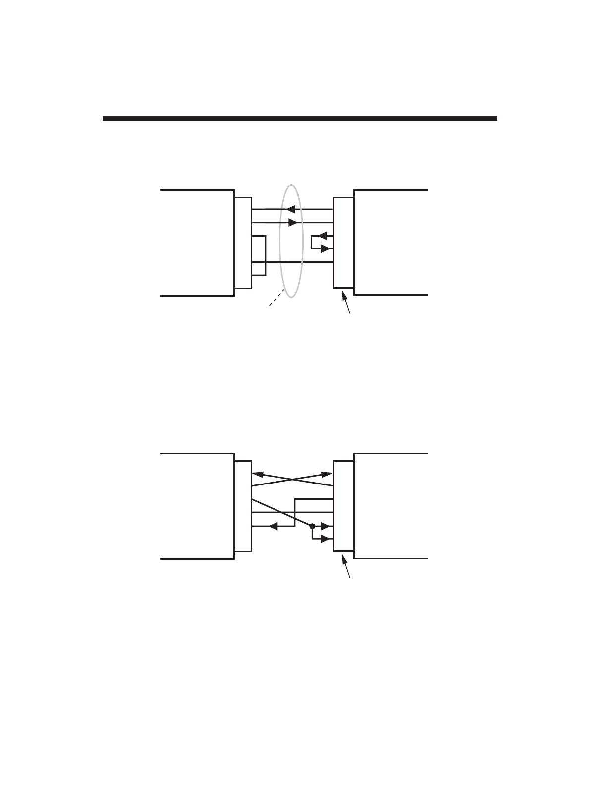
Page 47

If you did not order a specific
RS-232-C Interface Cable
with your 4078,
you will have to provide your own connection. Fig. 11 shows suggested
cabling between a 4078 and a computer, terminal, buffered printer, etc.,
that uses a
25-Pin RS-232-C Connector
. FOR MAXIMUM DATATRANSFER SPEED AND ACCURACY, A "FULL HANDSHAKE"
INTERCONNECTION IS GENERALLY RECOMMENDED (Fig. 11(a)).
However, cabling is also given for "INCOMING HANDSHAKE ONLY"
and "NO HANDSHAKE" situations (Figs. 11(b) and 11(c), respectively).
Following RS-232-C conventions, the device at each end of the
interface is seen as "DATA TERMINAL EQUIPMENT (DTE)."
Fig. 12 shows suggested cabling between a 4078 and a computer,
terminal, printer, etc., that uses a
9-Pin D-Subminiature Connector
for
its RS-232-C interface (such as an IBM PC/AT).
Please note that the cabling in Figs. 11 and 12 is by no means
definitive. In all cases, you should carefully study the literature
accompanying the specific RS-232-C device you wish to connect to
your 4078, to determine the cable arrangement that will create the
"handshake" you need (if any). On some devices, for example, the
DATA TERMINAL READY (DTR) signal may have a different name
(such as NOT BUSY) and may even appear on a pin other than No. 20
or No. 4.
NOTE: OPTIONAL IEEE-488 INTERFACING REQUIRES AN
EXTERNAL MODEL 10CIF488A IEEE Interface Adaptor. Complete
instructions will be supplied with this equipment.
B.1
4078/Computer RS-232-C Connections App. B
Page 48

App. B 4078/Computer RS-232-C Connections
B.2
25-Pin RS-232-C
Connector**
2
3
4
5
8
2
3
5
6
7
20
RECEIVE
TRANSMIT
DTR
COMMON
CTS
TRANSMIT
RECEIVE
CTS
DSR
COMMON
DTR
COMPUTER
FULL HANDSHAKE
(RECOMMENDED)
RS-232-C Interface
Connector—Male
(see Fig. 2)
*
1
2345
6
789
4000 Instrument
Required for connection of the 4000 instrument to an IBM or IBMcompatible computer, but not to a Daytronic Model PC-HSICA.
Male connector required for Model PC-HSICA.
*
**
Fig. 11 Suggested RS-232-C Interface Connections
(to 25-Pin RS-232-C Connector)
11(a)
25-Pin RS-232-C
Connector
RECEIVE
TRANSMIT
DTR
COMMON
CTS
TRANSMIT
RECEIVE
CTS
COMMON
DTR
INCOMING HAND-
SHAKE ONLY
2
3
4
5
8
2
3
5
7
20
COMPUTER
4000
Instrument
11(b)
Page 49
B.3
4078/Computer RS-232-C Connections App. B
25-Pin RS-232-C
Connector
2
3
4
5
8
2
3
4
5
7
20
RECEIVE
TRANSMIT
DTR
COMMON
CTS
TRANSMIT
RECEIVE
RTS
CTS
COMMON
DTR
COMPUTER
NO HANDSHAKE
4000 Instrument
11(c)
9-Pin RS-232-C
Connector
2
3
4
5
8
2
3
4
5
6
8
RECEIVE
TRANSMIT
DTR
COMMON
CTS
RECEIVE
TRANSMIT
DTR
COMMON
DSR
CTS
COMPUTER
4000
Instrument
Fig. 12 Suggested RS-232-C Interface Connections
(to 9-Pin RS-232-C Connector)
Page 50

Every Model 4078 will normally come with the UNIT LEGENDS and
BUTTON FUNCTION INDICATORS shown in Fig. 1, with the legend/
indicator negative already fitted in the 4078's front-panel "FRAME"
LABEL. Customized negatives are available as an option. Contact the
factory for precise installation instructions; IMPROPER INSTALLATION
CAN DAMAGE THE 4078 DISPLAY PANEL.
Unless other specified, the 4078 comes with only the front-panel "F1"
and "psi" indicators lit. To cause one or more legends and/or indicators to light up whenever instrument power is on, you must use the
ANNUNCIATOR (ANN) command. The front-panel "annunciators"
consist of the indicators that correspond to the
first five
buttons, plus
the three engineering-unit legends.* Thus, to turn ON Annunciator
Number n, where 1 ≤ n ≤ 8 (see Fig. 13 for the precise numbering), you
need only command
ANN n = 1 [CR]
To turn OFF Annunciator No. n, command
ANN n = 0 [CR]
* The SETUP indicator cannot be affected by the ANNUNCIATOR (ANN)
command. It will only be on when the 4078 is in "SETUP" mode.
C.1
App. C Legend and Indicator Annunciation
F2 F5F4 SETUP
1
8
6
7
F3
2345
F1
psi
lbs
lb-ft
Fig. 13 Front-Panel
"Annunciators"
Page 51

Under the "standard configuration," your 4078 is initially set for a fullscale transducer range of 3.00 mV/V. If your transducer's full scale is
0.75 or 1.5 mV/V, you need only enter the corresponding RANGE
(RNG) command to set the 4078 accordingly:
RNG 1 = .75M or RNG 1 = 1.5M [CR]
To reset the 4078 to the 3-mV/V range, command
RNG 1 = 3M [CR]
IF YOU NEED TO RESET THE 4078's INPUT RANGE, IT
SHOULD BE DONE BEFORE THE TRANSDUCER IS
CONNECTED.
Modifying the Input Range App. D
D.1
Page 52

E.1
App. E for a Lebow 1800 Series Transducer
Phase/Symmetry Adjustment
NOTE: WHEN USING THE 4078 WITH A LEBOW 1800 SERIES
TRANSDUCER, YOU SHOULD FIRST REPLACE THE 4078'S
INTERNAL 59K SHUNT RESISTOR WITH THE CALIBRATION
RESISTOR SUPPLIED WITH THE TRANSDUCER.
1. Locate the "CAL/RUN" Switch in the cable harness of the 1800
Series transducer. Place this switch in the "CAL" position.
2. Display the 4078's Channel No. 1 (see Section 2.d for "Selecting a
Channel for Display").
3. Establish a
zero input
for Channel 1 by removing all load from the
1800 Series transducer.
4. Switch in the shunt resistor for a positive up-scale reading of
Channel 1 by entering a command of
SHP 1 = ON [CR]
5. Adjust the rear-panel PHASE CONTROL until a
maximum reading
is obtained for Channel 1.
6. Disconnect the positive shunt by entering a command of
SHP 1 = OFF [CR]
7. Now zero the reading of Channel 1 by entering a command of
ZRO 1 = 0 [CR]
8. Enter once again a command of
SHP 1 = ON [CR]
9. Now "force" Channel 1 to read the "EQUIVALENT INPUT" VALUE
GIVEN BY THE TRANSDUCER MANUFACTURER FOR THE
CALIBRATION RESISTOR YOU INSTALLED IN THE 4078 (for a
discussion of EQUIVALENT INPUT, see Appendix F, below). If this
EQUIVALENT INPUT—
expressed in the desired engineering
units
—is "z," then command
FRC 1 = z [CR]
10. Disconnect the positive shunt and switch in the resistor for a
negative
reading by entering a command of
Page 53

SHN 1 = ON [CR]
11. Now adjust the 4078's SYMMETRY CONTROL to produce a
reading equal to the
negative
value of the same EQUIVALENT
INPUT "z" (or some other specific negative engineering-unit value,
if such a value is given by the transducer manufacturer for the
calibration resistor
).
12. Command
SHN 1 = OFF [CR]
13. Move the transducer's "CAL/RUN" Switch to the "RUN" position.
14. With the transducer load still at zero, again command
ZRO 1 = 0 [CR]
THE LEBOW 1800 / DAYTRONIC 4078 SYSTEM IS NOW FULLY
CALIBRATED. YOU NEED NOT PERFORM A SUBSEQUENT
"DEADWEIGHT" OR "SIMULATED" CALIBRATION.
E.2
for a Lebow 1800 Series Transducer App. E
Phase/Symmetry Adjustment
Page 54

This is an easier through generally less accurate technique than the
"TWO-POINT (DEADWEIGHT)" CALIBRATION discussed in Section
2.e. It is useful, however, when overall "deadweighting" is impossible or
inconvenient, and is good for an accuracy of about 0.2% (depending, of
course, on the accuracy of the specified EQUIVALENT INPUT, and on
the resistor/bridge tolerance and temperature). The known calibration
input is not produced by loading the transducer, as in the "deadweight"
method, but by shunting a resistor of known magnitude across one arm
of the strain-gage bridge, thereby "simulating" a particular up-scale
value of mechanical input. This known EQUIVALENT INPUT then
serves to determine the SCALING FACTOR for the channel.
The 4078 is equipped with a 59-kΩ, 0.1%
calibration resistor
which you
may, if you wish, replace with a resistor of some other value (straingage transducer manufacturers often supply such resistors with their
instruments, along with the exact values of EQUIVALENT INPUT
thereby produced—contact the factory for installation instructions).
EQUIVALENT INPUT can be approximated from a knowledge of the
Shunt Calibration Resistance (R
); the transducer's
Bridge Resistance
(B)
; and the transducer's
Full-Scale Sensitivity (K, in mV/V, full scale).
To determine the EQUIVALENT INPUT (X) as an approximate
percentage of full-scale output, you may use the following equation:
1. Apply an
accurately known
value of input loading to the source
transducer—a value (positive or negative) less than 50% of the
nominal full-scale rating. If it is possible to remove all load from the
transducer, thus establishing a true
zero input
for the 4078's
Channel 1, you should do so.
2. Enter a command of
ZRO 1 = z[CR]
where "z" is the numerical value of the known input, with appropriate polarity (in the "zero input" case, z = 0). This command
X
=
%
25000(mV/V)B
KR
App. F "Simulated" Calibration
F.1
Page 55

establishes the channel's ZERO OFFSET (i.e., the "b" term of its "y
= mx + b" equation).
3. To switch in the shunt resistor for a
positive
up-scale reading, enter
a SHUNT CALIBRATE—POSITIVE (SHP) command of
SHP 1 = ON [CR]
To switch in the resistor for a
negative
reading, enter a SHUNT
CALIBRATE—NEGATIVE (SHN) command of
SHN 1 = ON [CR]
4. Now command
FRC 1 = X [CR]
where "X" is the known EQUIVALENT INPUT produced by the
shunt, with appropriate polarity.
5. Before Channel 1 can resume normal measurement, its shuntcalibration switch must be opened. If it has been closed for a
positive up-scale reading, command
SHP 1 = OFF [CR]
—and if for a negative reading, command
SHN 1 = OFF [CR]
---------- NOTE ----------
Like all 4000 Series instruments, the 4078 permits calibration of
a relatively
nonlinear
input by setting up an internal LINEARIZATION TABLE of up to 15 "segments." The procedure is given in
the optional
System Instruction Manual.
F.2
"Simulated" Calibration App. F
Page 56

If, on powerup, your 4078 displays the "LO bat" warning, you should
take the following steps to replace the battery (READ ALL OF THESE
DIRECTIONS COMPLETELY BEFORE YOU BEGIN):
1. If possible, offload your 4078's present configuration data to disk
by means of the Upload Node Configuration routine in the
StartPAC 100 Software (you can use Download Node Configu-
ration to reload the configuration at a later time, if necessary).
2. Turn off the 4078 and disconnect the power cord and any other
cables attached to the rear panel.
IMPORTANT: YOU SHOULD
TAKE PRECAUTIONS TO AVOID
ELECTROSTATIC DISCHARGE
THAT MIGHT HARM THE 4078'S
MICROPROCESSOR. IF POSSIBLE, WORK ON AN ANTISTATIC SURFACE AND WEAR A
GROUNDING STRAP AROUND
YOUR WRIST. THE STRAP
SHOULD BE CONNECTED TO
EARTH GROUND.
3. Unscrew the two rear-panel
CLAMP SCREWS and slide
the CLAMP SLIDES rearwards out of their grooves
(see Fig. 3, Section 1.c).
4. Now remove the four screws
in the corners of the rear
panel (see Fig. 2).
5. Holding the 4078 with the rear panel upward, use a flat-tipped
screwdriver to gently pry up the rear panel from the instrument
case until you feel it loosen. The internal board connectors are
now disengaged from the front display assembly, and you can
easily pull the entire dual-board assembly out of the case.
G.1
App. G Changing the Battery
Battery
(CR-1/3N)
Rear Panel
Board Connector
+
–
Fig. 14 Location of Battery
Page 57

6. Locate the battery in the corner of the top board (see Fig. 14). It is
held in by two plastic clips. NOTE THE POLARITY OF THE
BATTERY TERMINALS, AS SHOWN IN THE FIGURE.
VERY IMPORTANT: YOU MUST USE A CR-1/3N 3-V LITHIUM
BATTERY IN THE 4078. YOU SHOULD HAVE THE REPLACEMENT
BATTERY READY TO INSTALL AS SOON AS YOU REMOVE THE
EXISTING (LOW) BATTERY. ONCE THE EXISTING BATTERY HAS
BEEN REMOVED FROM THE 4078, YOU WILL HAVE ONLY
ONE
MINUTE
TO REPLACE IT BEFORE CALIBRATION AND RUN-TIME
DATA ARE IRRETRIEVABLY LOST.
IF THIS DATA SHOULD BE LOST, YOU WILL NOT BE ABLE TO
RECALIBRATE THE 4078 IN THE FIELD, BUT MUST SEND IT BACK
TO THE FACTORY FOR RELOADING OF THE APPROPRIATE
ANALOG ALIGNMENT VALUES.
7. Using a small flat-tipped screwdriver, pry the existing battery out of
its clip socket. IMMEDIATELY INSERT THE NEW BATTERY INTO
THE SOCKET, BEING CAREFUL TO OBSERVE THE CORRECT
POLARITY OF THE TERMINALS. A backwards battery won't
damage the 4078, but it won't work either. Remember: you have
one minute
to replace the battery before calibration and run-time
data are lost.
8. Align the dual-board assembly with the guide slots on the inside of
the 4078 case and reinsert the assembly all the way (if it is wrongside-up, you won't be able to insert it).
9. Replace the four rear-panel corner screws. As you screw down
the rear panel, the internal board connectors will automatically
engage with the front display assembly.
10. Reinstall the CLAMP SLIDES.
11. Reattach the rear-panel cables and power connector. Then
reactivate the 4078. YOU WILL HAVE TO CYCLE POWER
TWICE. The first time you turn on the 4078, the "LO bat" warning
will reappear. Simply turn the unit off and on once again.
Changing the Battery App. G
G.2
Page 58

Daytronic Corporation
Dayton, OH • (800) 668-4745
www.daytronic.com
 Loading...