

Page 1
3500
INSTRUMENT SERIES
SB.3
INSTRUCTION MANUAL
Page 2

Copyright © 1997, Daytronic Corporation. All rights reserved.
No part of this document may be reprinted, reproduced, or used in any form or by
any electronic, mechanical, or other means, including photocopying and recording,
or in any information storage and retrieval system, without permission in writing from
Daytronic Corporation. All specifications are subject to change without notice.
Page 3

3500 Series Instruction Manual, v. SB.3
Pub. No. 3500M.3, Issued 1/97
3500
INSTRUMENT
SERIES
Part No. 91668
INSTRUCTION MANUAL
Daytronic Corporation
2211 Arbor Blvd. • Dayton, OH 45439-1521 • Tel (937) 293-2566 • Fax (937) 293-2586
www.daytronic.com
Page 4

C
ONTENTS
1INTRODUCTION
a. Using This Manual ........................................................................................................ 1.1
b. General Instrument Descriptions
1. Introduction ....................................................................................................................... 1.1
2. The Model 3510 Thermocouple Conditioner ....................................................... 1.2
3. The Model 3530 LVDT Conditioner .......................................................................... 1.2
4. The Model 3540 Frequency Input Conditioner .................................................... 1.2
5. The Model 3560 Voltage Conditioner ..................................................................... 1.3
6. The Model 3570 DC Strain Gage Conditioner ...................................................... 1.3
7. The Model 3578 AC Strain Gage Conditioner ...................................................... 1.3
c. Physical Layout .............................................................................................................. 1.4
d. Panel Mounting ...............................................................................................................1.6
e. Summary of Setup Button Functions ............................................................ 1.7
f. Summary of Logic I/O Functions ..................................................................... 1.8
g. Mnemonic Commands ............................................................................................. 1.9
2SETUP: CONNECTIONS AND POWER
a. Transducer Connections
1. The “Standard” Analog Input Connector ............................................................... 2.1
2. Connecting a Thermocouple to the Model 3510 ................................................ 2.1
3. Connecting an LVDT or Variable Reluctance Transducer
to the Model 3530 .......................................................................................................... 2.2
4. Connecting a Frequency Source to the Model 3540 ........................................ 2.4
5. Connecting a Voltage Source to the Model 3560 .............................................. 2.6
6. Connecting a DC Strain Gage Transducer to the Model 3570 ...................... 2.7
7. Connecting an AC Strain Gage Transducer to the Model 3578 .................... 2.8
b. RS-232 (“Single-Node”) Connections .......................................................... 2.10
c. RS-485 (“Multinode Network”) Connections ......................................... 2.12
d. Analog Output Connections .............................................................................. 2.15
e. Logic Input/Output Connections ................................................................... 2.16
f. Powerup ............................................................................................................................ 2.18
3SETUP: INSTRUMENT CONFIGURATION
a. Configuring Through the Front Panel
1. Entering and Exiting SETUP MODE .......................................................................... 3.1
2. Security Code .................................................................................................................. 3.2
3. RS-232 Communications Parameters: COM Key .............................................. 3.3
4. RS-485 Communications Parameters: COM Key .............................................. 3.7
5. Input Range: RANGE Key ........................................................................................... 3.8
a. Setting the Model 3510’s TC Type and Scale ................................................ 3.8
b. Setting the Model 3530’s LVDT Input Range .................................................. 3.9
c. Setting the Model 3540’s Frequency Input Range and Sensitivity ...... 3.10
d. Setting the Model 3560’s Voltage Input Range .......................................... 3.10
e. Setting the Model 3570’s DC Strain Gage Input Range
and Excitation .......................................................................................................... 3.11
f. Setting the Model 3578’s AC Strain Gage Input Range ........................... 3.11
iv
Page 5

C
ONTENTS
6. Filter: FILTER Key ......................................................................................................... 3.12
7. Analog Output: ANO Key .......................................................................................... 3.13
8. Limits: LIMIT Key .......................................................................................................... 3.14
9. Tare Offset: TARE Key ................................................................................................ 3.17
10. Print and Output Parameters: PRINT Key ........................................................... 3.18
b. Configuring Through the RS-232/485 Interface .................................. 3.20
1. Security Code ............................................................................................................... 3.20
2. Communications Parameters ................................................................................. 3.20
3. Thermocouple Type (Model 3510 ONLY) ........................................................... 3.21
4. Input Range or Scale .................................................................................................. 3.21
5. Excitation (Models 3570 and 3578 ONLY) .......................................................... 3.22
6. Sensitivity (Model 3540 ONLY) ............................................................................... 3.22
7. Filter .................................................................................................................................. 3.22
8. Analog Output .............................................................................................................. 3.23
9. Limits ................................................................................................................................ 3.23
10. Tare Offset ...................................................................................................................... 3.23
11. Print and Output Parameters ................................................................................... 3.23
4SETUP: INSTRUMENT CALIBRATION
a. Introduction: Calibration Techniques ............................................................ 4.1
1. Absolute Calibration ...................................................................................................... 4.1
2. “Actual” Two-Point (Deadweight) Calibration ....................................................... 4.2
3. “Simulated” Two-Point (Deadweight) Calibration ............................................... 4.2
4. Internal 15-Segment Linearization ........................................................................... 4.3
5. Calculated Calibration .................................................................................................. 4.3
6. Calculated Calibration Via Mnemonic Command .............................................. 4.3
b. Phase and Symmetry Adjustment of the
Model 3578 AC Strain Gage Conditioner .................................................... 4.4
c. Calibrating Through the Front Panel
1. Using the CAL Key ......................................................................................................... 4.8
2. “Actual” Two-Point (Deadweight) Calibration ....................................................... 4.8
3. “Simulated” (Shunt) Calibration for a Strain Gage Conditioner
(Model 3570 or 3578) ................................................................................................. 4.10
4. 15-Segment Linearization
a. Introduction .............................................................................................................. 4.12
b. By “TABLE” ............................................................................................................... 4.13
c. By “FORCE” .............................................................................................................. 4.15
5. “Calculated” Calibration
a. For the Models 3510, 3530, 3540, and 3560 ............................................... 4.16
b. For the Model 3570 (ONLY) ............................................................................... 4.17
d. Calibrating Through the RS-232/485 Interface .................................... 4.18
1. Setting the Active Calibration Method .................................................................. 4.18
2. “Two-Point” Calibration .............................................................................................. 4.19
3. 15-Segment Linearization ........................................................................................ 4.19
4. “Calculated” Calibration ............................................................................................ 4.20
v
Page 6

C
ONTENTS
5RUN-TIME OPERATION
a. RS-232/485 Communications
1. RS-232/485 Outputs: CHN and DMP Commands ............................................ 5.1
2. Data-Transmission Format ......................................................................................... 5.1
3. “Opening” a Node to Receive Commands from the Computer ................... 5.2
b. Peak Capture ................................................................................................................... 5.3
c. Tare and Reset ................................................................................................................ 5.5
d. Initiating Hard-Copy Printouts ............................................................................. 5.6
e. Track/Hold Function .................................................................................................. 5.7
Appendix A 3500 SERIES SPECIFICATIONS
1. General Specifications ........................................................................................... A.1
2. Individual Conditioner Specifications
a. Model 3510 Thermocouple Conditioner .............................................................. A.2
b. Model 3530 LVDT Conditioner ................................................................................. A.3
c. Model 3540 Frequency Input Conditioner ........................................................... A.4
d. Model 3560 Voltage Conditioner ............................................................................. A.5
e. Model 3570 DC Strain Gage Conditioner ............................................................. A.6
f. Model 3578 AC Strain Gage Conditioner ............................................................. A.7
Appendix B COMMAND AND RESPONSE SYNTAX
1. Introduction: RS-232 and RS-485 Modes .................................................... B.1
2. The OPEN (OPN) Command ................................................................................ B.1
3. Response to “Invalid” Commands ................................................................. B.1
4. Setup Commands ....................................................................................................... B.2
5. Interrogation Commands ...................................................................................... B.2
6. Imperative Commands ............................................................................................ B.2
7. Commands That Initiate Data Transmissions ....................................... B.3
8. Table of Mnemonic Commands ....................................................................... B.3
Appendix C TABLE OF ERROR NUMBERS ...................................... C.1
Appendix D NETWORKING GUIDELINES ........................................... D.1
Appendix E RUN-TIME BUTTON FUNCTIONS ............................. E.1
Appendix F STANDARD LOGIC CONFIGURATION ................... F.1
vi
Page 7

C
ONTENTS
Illustrations
1(a) Typical “Run-Time” Display ........................................................................................... 1.4
1(b) Typical “Setup” Display .................................................................................................. 1.4
2(a) Rear Panel for the Model 3510 Thermocouple Conditioner
and the Model 3578 AC Strain Gage Conditioner ................................................ 1.5
2(b) Rear Panel for All Other 3500 Models ...................................................................... 1.6
3 Panel Mounting ................................................................................................................. 1.6
4 Use of NUMERIC BUTTONS in SETUP MODE ...................................................... 1.8
5(a) Standard Logic INputs and Outputs ......................................................................... 1.8
5(b) Shunt-Control Logic Inputs for the Model 3570 DC Strain Gage
Conditioner (ONLY) ..........................................................................................................1.9
6 Model 3510 Transducer Cabling ............................................................................... 2.2
7(a) Model 3530 Transducer Cabling: 5-Wire LVDT Cabling
(under 20 ft. in length) .................................................................................................... 2.3
7(b) Model 3530 Transducer Cabling: 7-Wire LVDT Cabling (20 ft. or longer) ... 2.3
7(c) Model 3530 Transducer Cabling: 3-Wire Variable Reluctance Cabling
(under 20 ft. in length) .................................................................................................... 2.3
7(d) Model 3530 Transducer Cabling: 5-Wire Variable Reluctance Cabling
(20 ft. or longer) ................................................................................................................ 2.4
8(a) Model 3540 Transducer Cabling: Differential (Floating) Frequency Input .. 2.5
8(b) Model 3540 Transducer Cabling: Single-Ended (Grounded) Frequency
Input ...................................................................................................................................... 2.5
8(c) Model 3540 Transducer Cabling: Input from a Zero-Velocity Sensor .......... 2.5
8(d) Model 3540 Transducer Cabling for Elimination of DC Offset ........................ 2.5
8(e) Model 3540 Transducer Cabling for Suppression of High-Frequency
Noise .................................................................................................................................... 2.5
9(a) Model 3560 Transducer Cabling: General Voltage Source ............................. 2.6
9(b) Model 3560 Transducer Cabling: External Potentiometer ............................... 2.6
9(c) Model 3560 Transducer Cabling: External DC-to-DC LVDT ............................. 2.6
10(a) Model 3570 Transducer Cabling: 4-Wire Cabling (under 20 ft. in length) ... 2.7
10(b) Model 3570 Transducer Cabling: 8-Wire Cabling (20 ft. or longer) .............. 2.7
11(a) Model 3578 Transducer Cabling: 4-Wire Cabling (under 20 ft. in length) ... 2.8
11(b) Model 3578 Transducer Cabling: 8-Wire Cabling (20 ft. or longer) .............. 2.8
11(c) Model 3578 Transducer Cabling: Installation of User’s External Shunt
Calibration Resistor ......................................................................................................... 2.9
11(d) Model 3578 Transducer Cabling: 8-Wire Cabling to LEBOW 1600
SERIES TRANSDUCER (ONLY) ................................................................................... 2.9
12 Suggested RS-232-C Interface Connections (to 25-Pin RS-232-C
Connector) ....................................................................................................................... 2.11
13 Suggested RS-232-C Interface Connections (to 9-Pin RS-232-C
Connector) ....................................................................................................................... 2.12
14(a) Connections for a Network of Three Instrument Nodes
(where the first is a 3500 Series Instrument) ...................................................... 2.13
14(b) RS-485 Cabling Between the Model 5E485 and the FIRST Network
Node (if it is a 3500 Series Instrument) ................................................................. 2.14
14(c) RS-485 Cabling Between Successive 3500 or 4000 Instrument Nodes .. 2.14
14(d) RS-485 Cabling Between a 3500 or 4000 Instrument Node and a
5000 Instrument Node ................................................................................................ 2.14
15 Analog Output Programming Pins .......................................................................... 2.15
16 Analog Output Connections (ALL Conditioners) ............................................... 2.16
(cont’d)
vii
Page 8

C
ONTENTS
17(a) Logic I/O Connections: Input from External Switch .......................................... 2.17
17(b) Logic I/O Connections: External TTL Logic ......................................................... 2.17
17(c) Logic I/O Connections: External Controller ......................................................... 2.17
17(d) Logic I/O Connections: Output to External Relay .............................................. 2.18
18 Limit Zones ...................................................................................................................... 3.15
19 High and Low Hysteresis Windows ........................................................................ 3.16
20 Symmetry and Phase Adjustment Controls for the Model 3578 ................... 4.4
21 Typical Linearization Curve with Seven Segments .......................................... 4.12
22 Capture and Hold of Successively Higher-Valued Maxima ............................ 5.4
23 Capture and Hold of Successively Lower-Valued Maxima Using
Peak Reset ......................................................................................................................... 5.4
24 Tare Offset Operation .................................................................................................... 5.5
25 3500 Physical Dimensions .......................................................................................... A.1
viii
Page 9

INTRODUCTION
1.a USING THIS MANUAL
THIS MANUAL TREATS ALL SIX STANDARD MODELS BELONGING TO THE
DAYTRONIC 3500 INSTRUMENT SERIES. THESE MODELS ARE AS FOLLOWS:
• the Model 3510 Thermocouple Conditioner
• the Model 3530 AC LVDT Conditioner
• the Model 3540 Frequency Input Conditioner
• the Model 3560 Voltage Conditioner
• the Model 3570 DC Strain Gage Conditioner
• the Model 3578 AC Strain Gage Conditioner
EXCEPT WHERE OTHERWISE STATED, THE INFORMATION IN THIS MANUAL
APPLIES EQUALLY TO ALL SIX MODELS.
DESCRIPTIONS, PROCEDURES, AND OPERATIONS SPECIFIC TO A GIVEN
MODEL OR MODELS WILL BE CLEARLY IDENTIFIED AS SUCH.
1.b GENERAL INSTRUMENT DESCRIPTIONS
1
1.b.1 INTRODUCTION
Every 3500 Series instrument can be completely set up and operated either
through the front-panel keypad or via simple mnemonic commands received
from an external computer or terminal through its RS-232/485 Interface Port.
The instrument can transmit data from this port in response to an interrogation
from an external computer, or can send it to an RS-232 serial printer when the
PRINT button is pressed (assuming that it is set to RS-232 mode). When in RS485 mode, a given 3500 instrument can represent one of up to 99 data-collection
"nodes" of a high-speed multidrop network.
Features common to all models include
• continuous dual-limit monitoring with front-panel annunciation, programmable
hysteresis windows, and TTL-level logic control outputs
• front-panel security code
• real-time positive peak capture or track/hold operation
• user-settable automatic tare offset
• internal 15-segment linearization for calibration of nonlinear inputs (except for
the Model 3510 Thermocouple Conditioner)
• selectable digital filtering
• selectable analog filtering (except for the Model 3510 Thermocouple Condi-
tioner)
• scalable analog output to drive strip-chart recorders or other devices (it may
also be used as feedback for a PID control loop)
• data-transmission formatting options, including "header" and "tailer" character
strings, node-number "echo," and limit-status indication
1.a USING THIS MANUAL 1.b GENERAL INSTRUMENT DESCRIPTIONS
1.1
Page 10

1
INTRODUCTION
• logic-input control of peak capture, unlatching of latched limit conditions,
application of tare offset, and initiation of hard-copy printout
For complete specifications, see Appendix A.
1.b.2 THE MODEL 3510 THERMOCOUPLE CONDITIONER
This instrument accepts a temperature signal from a Type B, E, J, K, R, S, or T
Thermocouple. The sensor may be grounded or ungrounded. The conditioner
employs "absolute" calibration, which means that no calibration is required by the
user, once the proper "TC Type" is entered. During operation, appropriate reference-junction compensation, digital linearization, and engineering-unit scaling are
automatically applied. Detection of "open" thermocouples is also provided.
The 3510’s special rear connector assembly contains a thermistor for precise
measurement of the reference-junction temperature. Therefore, no external cold
junction is required—although the user may supply his own Controlled Ambient
Temperature Zone for reference-junction purposes, if desired.
1.b.3 THE MODEL 3530 LVDT CONDITIONER
This instrument measures displacement, force, pressure, and other parameters
obtained with a 5- or 7-wire linear variable differential transformer (LVDT)
capable of 3280-Hz operation and having primary impedance of 80 Ω or greater.
It can also be used with a 3- or 5-wire variable reluctance transducer. The
"normal" input range can be 0-150, 0-300, or 0-600 mV/V, full scale. Input provisions also exist for "long-stroke" LVDT's (0-1, 0-2, or 0-4 V/V, full scale). Nominal 3
V-AC (rms) excitation is supplied.
1.b.4 THE MODEL 3540 FREQUENCY INPUT CONDITIONER
This instrument is used for measurement of flow, rpm, and other phenomena that
can be sensed by pulse transformer transducers with two-wire isolated windings
(tachometer pickups, turbine flowmeters, etc.), transistor or logic-circuit drivers,
"zero-velocity" (true digital output) sensors, and similar frequency-generating
transducers. It will accept any AC or unipolar pulse signal, floating or grounded,
irrespective of waveform. Input range is from 10% to 100% of 250, 500, 1000,
2000, 4000, 8000, 16000, or 32000 Hz.
The 3540’s analog-input threshold level is selectable to accommodate signals
from 100 mV to 100 V, thus guaranteeing reliable triggering when the input is at
the low end of the frequency range. Capacitive coupling of 0.1 µF is provided for
low-frequency inputs, to eliminate false triggering by signal noise or any DC offset
that exists for the frequency signal. For "zero-velocity" sensors, an excitation of
nominal ±5 V-DC ± 5% is supplied.
When you know the manufacturer-supplied full-scale rating of the frequency
source (or the highest frequency expected to be measured), the Model 3540’s
measurement channel can be quickly calibrated by issuing an "FRQ" command
through the RS-232/485 Interface Port.
1.2
1.b GENERAL INSTRUMENT DESCRIPTIONS
Page 11

INTRODUCTION
1.b.5 THE MODEL 3560 VOLTAGE CONDITIONER
This is a general-purpose instrument for conditioning, displaying, and monitoring
the signal received from a DC-to-DC LVDT, potentiometer-type sensor, or other
external two-wire voltage source, either floating (differential) or grounded (single-ended). The input signal may also represent output from some other instrument system. Allowable full-scale voltage ranges are ±0.5, ±1.0, ±2.0, ±5.0, ±10.0,
and ±20.0 V-DC (up to ±100 V without damage). A ±12-V excitation is supplied for
sources that require it.
1.b.6 THE MODEL 3570 DC STRAIN GAGE CONDITIONER
This is a general-purpose instrument for input of pressure, force, torque, weight,
and other variables measured by conventional DC-excited strain gage trans-
ducers. It accepts a single input from any conventional 4-arm strain gage bridge,
nominal 120 ohms or higher, with a full-scale range of 0.75, 1.5, or 3.0 mV/V.
(User-supplied bridge-completion circuitry allows input from a 2-wire 1/4-bridge,
3-wire 1/4-bridge, or 1/2-bridge gage configuration.) The user may select a nominal excitation level of 2, 5, or 10 V-DC. Remote sensing of bridge voltage yields
consistently stable ratiometric measurement, unaffected by possible power-supply drift.
1
Simple two-point "zero and span" calibration is provided for the 3570’s input
channel. In addition, a 100-kΩ, 0.1% shunt resistor is supplied. You can use this
resistor—or one of your own—to apply an "equivalent input" for calibration purposes, when the transducer's full-scale mV/V sensitivity is accurately known. The calibration shunt may be switched in and out for either a positive or negative
up-scale reading via simple commands issued to the RS-232/485 port or by
means of logic-level command signals through the rear Analog Input Connector.
A third calibration technique for the Model 3570 involves application of an "MVV"
command through the RS-232/485 Interface Port when both "mV/V" sensitivity
and corresponding full-scale rating of the transducer are known.
1.b.7 THE MODEL 3578 AC STRAIN GAGE CONDITIONER
This instrument is similar to the Model 3570 DC Strain Gage Conditioner, above,
but is of phase-sensitive carrier-amplifier design. Intended for applications involv-
ing transformer-coupling to the transducer bridge (as with rotary-transformer
torque sensors), it can also be used when high sensitivity is required or where
the electrical environment is especially noisy. Responding only to the modulated
carrier frequency, the 3578 rejects extraneous voltages that can cause errors in
DC systems, particularly when there is a need to "blow up" a portion of the transducer range.
The Model 3578 accepts input from a 4-arm bridge of nominal 90 ohms or higher,
and a full-scale range of 0.75, 1.50, or 3.00 mV/V. Excitation is fixed at 3 V-AC
(rms) at 3280 Hz. There are user-settable phase and symmetry controls. This
conditioner also offers the same shunt calibration provisions as the 3570, except
that shunt calibration of the AC Strain Gage Conditioner cannot be controlled via
logic-input commands.
1.b GENERAL INSTRUMENT DESCRIPTIONS
1.3
Page 12
1
INTRODUCTION
1.c PHYSICAL LAYOUT
Study the following diagrams to acquaint yourself with the most important front
and rear elements.
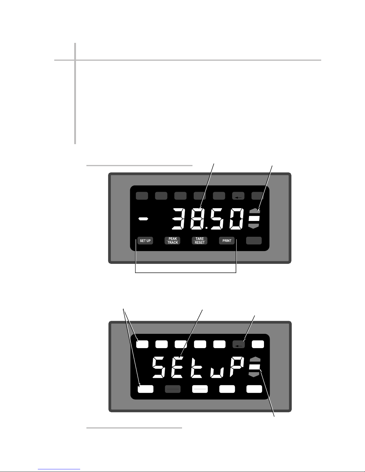
Fig. 1(a) shows a typical "RUN-TIME" display, with "live" data and limit-status
annunciation. Note the four front-panel buttons that are active (but not necessarily lit) during normal run-time operation. For a full description of run-time button
functions, see Appendix E.
Fig. 1(b) shows a typical SETUP display—specifically, the display that appears
after the security code has been entered and the unit is ready for any of the frontpanel setup procedures given in Sections 3.a and 4.a.
Fig. 1(a) Typical “Run-Time” Display
RANGE
COM
CAL FILTER ANO
Active Run-Time Buttons
Active Setup
Buttons are lit
Setup message or
parameter value
"Live" Data
Display
"Live" Limit
Status Indicators
DEC
LIMIT
HI
OK
LO
ENTER
"DEC" button lights when
decimal-point location of
setup parameter can be
changed
Fig. 1(b) Typical “Setup” Display
1.4
1.c PHYSICAL LAYOUT
COM
SET UP
RANGE
CAL FILTER ANO
PEAK
TRACK
TARE
RESET
DEC
PRINT ENTER
LIMIT
HI
OK
LO
Limit Status Indicators
updated with every change
of the display
Page 13
INTRODUCTION
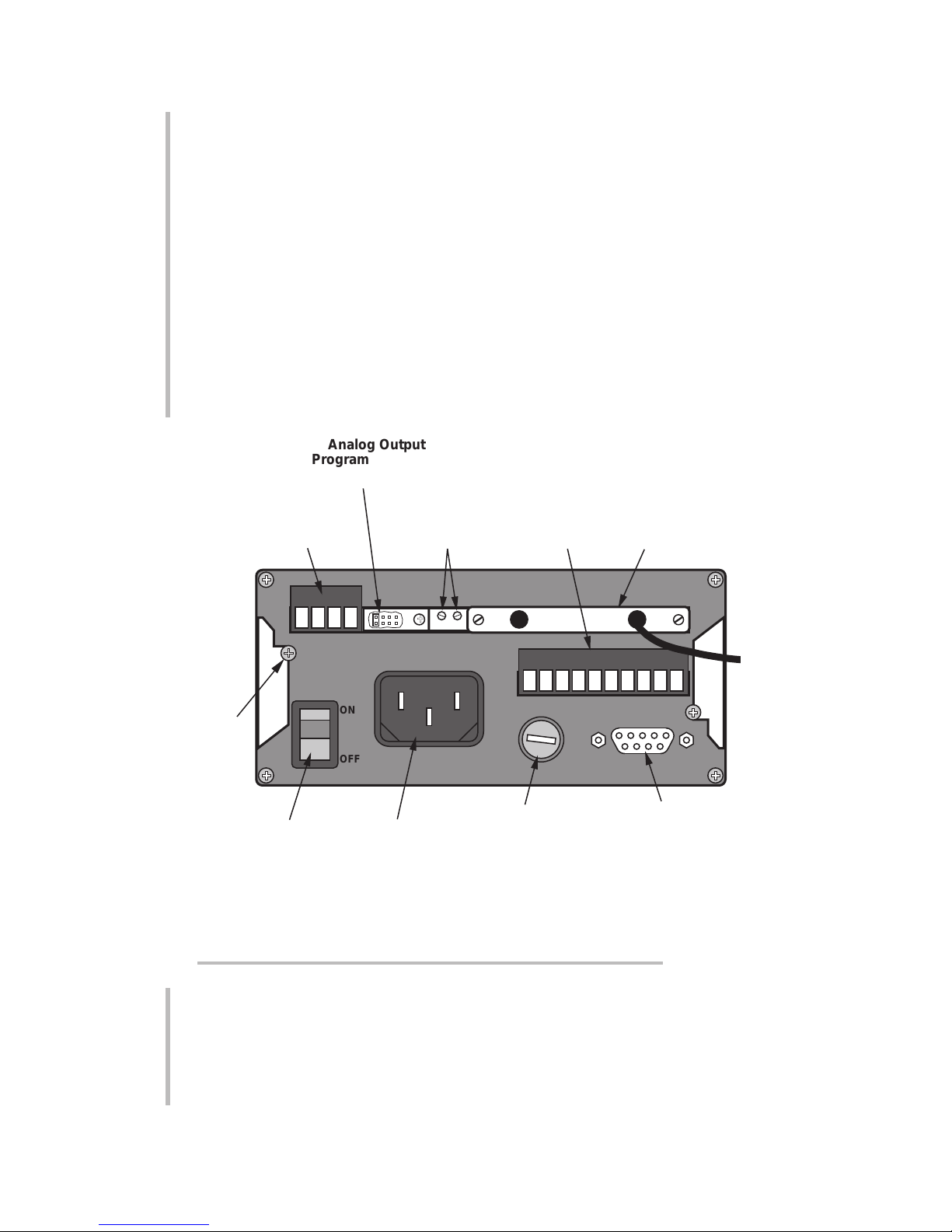
Analog Output
Connector
(see Fig. 16)
Conditioner Connector
—attaches to Analog
Input Board
(see Fig. 6 or 11)
Logic I/O
Connector
(see Figs. 5, 17)
Fuse
(0.5-amp SLO-
BLO)
ON-OFF
Switch
AC Power
Connector
RS-232/485 Inter-
face Connector
(see Figs. 12 - 14)
PanelMount
Clamp
Screw
ON
OFF
+
+
Analog Output
Programming Pins*
(behind cover plate—see Fig. 15)
Symmetry and
Phase Controls*
(see Fig. 20)
* Not present on the Thermocouple Conditioner.
NOTE: Your instrument is supplied with a large assortment of standard engineering unit legends on a 4" x 5 1/2" dry transfer sheet. The selected legend may be
rubbed directly onto the instrument's front-panel frame using the tip of a ball-point
pen or the blunt end of a stylus or other burnishing tool. DO NOT PRESS TOO
HARD. You can easily make up your own legends, since the sheet includes individual numerals, upper- and lower-case letters, ampersand ("&"), and Greek "∆,"
"ø," "µ," and "π."
The two rear panel types are shown below. The Model 3510 Thermocouple
Conditioner and the Model 3578 AC Strain Gage Conditioner have the rear
panel illustrated in Fig. 2(a). Each of these instruments employs a special CONDITIONER CONNECTOR that attaches directly to the rear edge of the unit's internal
Analog Input Board. In addition, the 3578 (only) has rear-panel Symmetry and
Phase Controls. All other models use a standard "clip-on" Analog Input Connector like that shown in Fig. 2(b).
1
Fig. 2(a) Rear Panel for the Model 3510 Thermocouple
Conditioner and the Model 3578 AC Strain Gage Conditioner
1.c PHYSICAL LAYOUT
1.5
Page 14
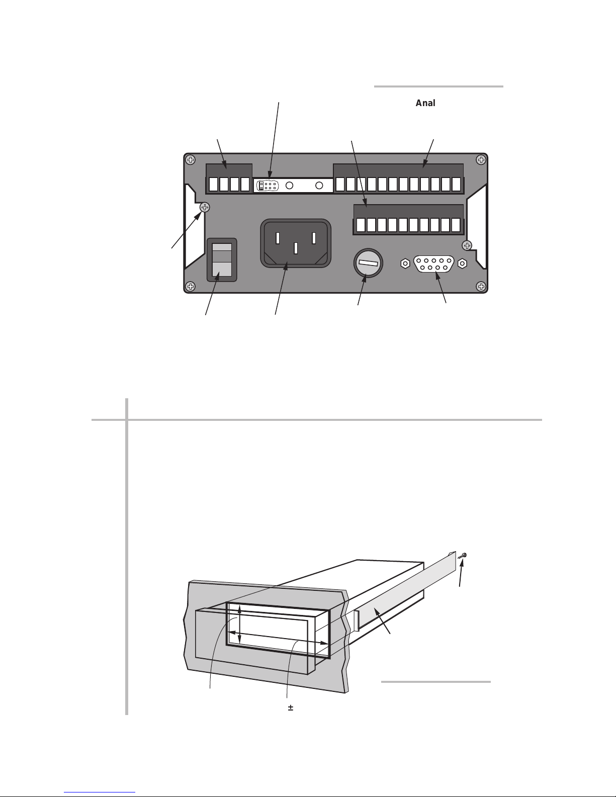
1
Analog Output
Connector
(see Fig. 16)
Analog Input
Connector**
(see Fig. 7, 8, 9,
or 10)
Logic I/O
Connector
(see Figs. 5, 17)
Fuse
(0.5-amp SLO-
BLO)
ON-OFF
Switch
AC Power
Connector
RS-232/485 Inter-
face Connector
(see Figs. 12 - 14)
PanelMount
Clamp
Screw
ON
OFF
+
+
Analog Output
Programming Pins*
(behind cover plate—see Fig. 15)
+
Not present on the Frequency Conditioner.
The number of connector terminals will vary with the conditioner type.
*
**
138 ± 1.0 mm
(5.43 ± 0.04 in)
68 ± 0.7 mm
(2.68 ± 0.03 in)
CLAMP SLIDE
CLAMP
SCREW
INTRODUCTION
Fig. 2(b) Rear Panel for All
Other 3500 Series Models
1.d PANEL MOUNTING
You can easily mount the instrument in your own precut panel. Cutout dimensions for a panel-mounted unit are standard DIN (see Fig. 3); panel thickness
should not exceed 6 mm (0.24 in).
Simply unscrew the two rear-panel CLAMP SCREWS and slide the CLAMP
SLIDES rearwards out of their grooves (THE FRONT BEZEL NEED NOT BE
REMOVED). Insert the unit through the panel cutout, from the front of the panel (if
the unit has rubber feet, these will have to be removed). Then reinstall the
CLAMP SLIDES, and tighten the CLAMP SCREWS until the instrument is securely
mounted.
Fig. 3 Panel Mounting
1.6
1.d PANEL MOUNTING
Page 15

INTRODUCTION
1.e SUMMARY OF SETUP BUTTON FUNCTIONS
The use of the SETUP buttons is explained in detail in Sections 3.a and 4.a. The
following table summarizes the relevant functions:
Button Button Function (in SETUP MODE):
1
SET UP
TARE
RESET
PRINT
COM
RANGE
CAL
FILTER
ANO
Used to exit current setup procedure ("COM," "RANGE," "CAL,"
etc.) or to exit SETUP MODE.
Used to enter a value into the TARE REGISTER.
Used to enter desired PRINT AND OUTPUT PARAMETERS:
printing interval; node-number "echo" (ON/OFF); and limit-status indication (ON/OFF).
Used to enter desired COMMUNICATIONS PARAMETERS:
baud rate; number of data bits; number of stop bits; parity;
node number; INPUT TERMINATOR character; and OUTPUT
TERMINATOR character(s).
Used to enter desired INPUT RANGE or SCALE, plus other
parameters, where applicable (EXCITATION, SENSITIVITY, etc.)
Used for CALIBRATION of the analog input ("Two-Point," "Linearization," or "Calculated").
Used to set the ANALOG and DIGITAL FILTERS.
Used to scale the ANALOG OUTPUT.
DEC
LIMIT
ENTER
In addition to the above SETUP buttons, the instrument provides two NUMERIC
BUTTONS for each displayed character of the LCD display, plus a polarity "sign"
button. These buttons let you change the value of a displayed number or step
forwards or backwards through a displayed series of allowed setup values. In
general, to increase by "1" the numeric value of a displayed digit (up to a maximum of "9"), press the TOP LCD SEGMENT of that digit, whether or not it is lit. To
decrease by "1" the numeric value of a displayed digit (down to a minimum of "0"),
press the BOTTOM LCD SEGMENT of that digit, whether or not it is lit. To change
the polarity of the displayed number, press the "minus-sign" segment at the
extreme left of the display (whether or not it is lit). The NUMERIC BUTTONS are
only active when the instrument is in SETUP MODE.
Used to change DECIMAL-POINT LOCATION for certain setup
values.
Used to enter LIMIT PARAMETERS: high limit; high hysteresis;
high latch (ON/OFF); low limit; low hysteresis; low latch
(ON/OFF).
Used to display the "existing value" of a setup parameter and
to finalize entry of a modified value.
1.e SUMMARY OF SETUP BUTTON FUNCTIONS
1.7
Page 16
1
SET UP
TARE
RESET
PRINT ENTER
HI
OK
LO
COM
RAN
FILTER ANO
DEC
LIMIT
Press top segment to
increment digit (up to "9")
Press bottom segment to
decrement digit (down to "0")
Press "–"
segment to
change polarity
INTRODUCTION
Fig. 4 Use of
NUMERIC
BUTTONS in
SETUP MODE
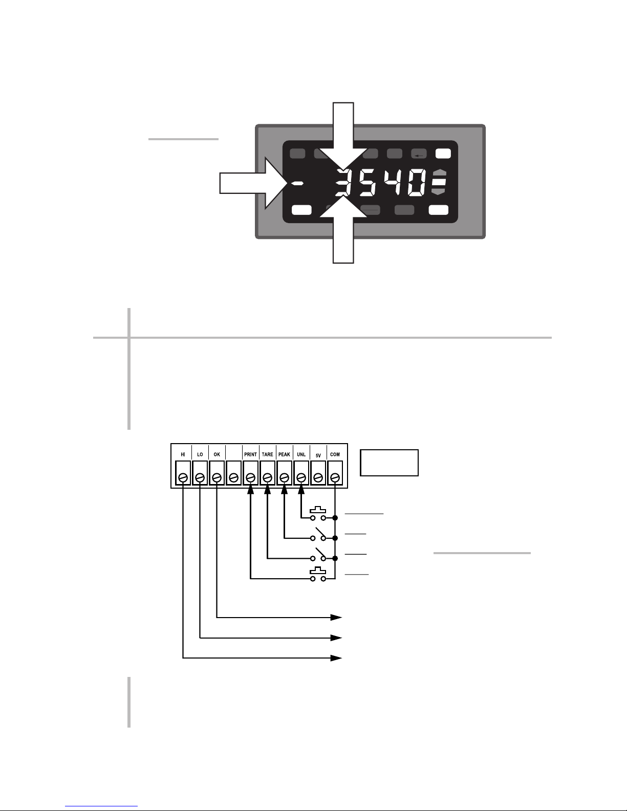
1.f SUMMARY OF LOGIC I/O FUNCTIONS
The rear-panel LOGIC I/O CONNECTOR provides seven active logic input/output
bits in open-collector, negative-true form, where the "Logic 1" state is defined as
nominal 0 V-DC and "Logic 0" as nominal +5 V-DC. The standard logic I/O configuration is shown in Fig. 5(a), below, with reference to the 10-terminal Logic I/O
Connector on the rear of the unit. For recommended logic interconnections, see
Section 2.e. Each I/O function is fully described in Appendix F.
+
*
PLEASE NOTE: THE MINIMUM TIME ALLOWED BETWEEN ACTIVATION AND
REACTIVATION OF ANY OF THE FOUR LOGIC CONTROL INPUTS IS 100 MILLISECONDS.
*
Ground connections to
be provided by user.
See also Fig. 17(a).
LOGIC LOW
TO ENABLE
Logic Inputs:
UNLATCH
PEAK
TARE
PRINT
Logic Outputs:
"LIVE" DATA IN
"OK" ZONE
"LIVE" DATA IN
"LESS THAN" ZONE
"LIVE" DATA IN
"GREATER THAN" ZONE
Fig. 5(a)
Standard Logic
Inputs and Outputs
1.8
1.f SUMMARY OF LOGIC I/O FUNCTIONS
Page 17

INTRODUCTION
ANALOG INPUT CONNECTOR
–
SHLD
SHUNT CAL
CONTROL
COM
SIG
+
–
SIGCOM
PWR
*
Ground
connections to
be provided by
user. See also
Fig. 17(a).
*
LOGIC LOW
TO ENABLE
Logic Inputs:
+ CALIBRATE
– CALIBRATE
You can use the three logic control outputs to actuate solenoid valves, illuminate
panel displays, sound alarms, start and stop motors or pumps, initiate and control
safety shut-down sequences, and perform many other automation tasks that
require "intelligent" switching, even of substantial amounts of power.
In addition to the standard logic inputs and outputs provided by the LOGIC I/O
CONNECTOR, the Model 3570 DC Strain Gage Conditioner (ONLY) also
accepts two negative-true logic inputs at its rear-panel ANALOG INPUT CONNECTOR. These two inputs, shown in Fig. 5(b), let the operator directly control the
SHUNT CALIBRATION process, which is explained in detail in Section 4. Again,
see Appendix F for a full description of these logic functions.
Fig. 5(b)
Shunt-Control Logic
Inputs for the Model
3570 DC Strain Gage
Conditioner (ONLY)
1
1.g MNEMONIC COMMANDS
There are two ways to issue commands to a 3500 Series instrument. One way is
through the front-panel push buttons. These buttons allow you
• to enter all necessary SETUP COMMANDS, as explained in Sections 3.a and
4.a*; and also
• to enter RUN-TIME COMMANDS for control of positive peak capture, application of tare offset, and initiation and halting of hard-copy transmissions (see
Sections 5.b, 5.c, and 5.d).
The second way to issue commands to the instrument is via the RS-232/485
Computer/Network Communications Interface. When set to the RS-232 (SINGLENODE) mode, this interface will accept commands from a connected computer,
terminal, or other RS-232-C device. When the unit is used in the RS-485 (MULTINODE) mode, commands will normally originate from an application program in the
network's supervisory computer.
In either RS-232 or RS-485 mode, commands to the instrument must be transmitted in a standard ASCII Command Syntax. This syntax uses simple three-letter
* As explained in Section 3.a.2, if a nonzero SECURITY CODE has been specified, the operator will
have to enter that code before any SETUP COMMANDS can be applied via the front-panel buttons.
1.g MNEMONIC COMMANDS
1.9
Page 18

1
INTRODUCTION
English mnemonics, and includes SETUP ("WRITE"), INTERROGATION ("READ"),
and TRANSMISSION-INITIATING commands. In RS-485 (MULTINODE) operation,
every command received at the RS-232/485 Interface Port will evoke a response
from that port (either "ACKNOWLEDGED," "NOT ACKNOWLEDGED," or the requested PARAMETER or DATA VALUE(S)). For a complete listing of mnemonic
commands and responses, see Appendix B.
1.10
1.g MNEMONIC COMMANDS
Page 19

SETUP: CONNECTIONS AND POWERUP
2.a TRANSDUCER CONNECTIONS
2.a.1 THE “STANDARD” ANALOG INPUT CONNECTOR
All 3500 Series instruments except the Model 3510 Thermocouple Conditioner
and the Model 3578 AC Strain Gage Conditioner use the "standard" Analog
Input Connector. Shown in Fig. 2(b), this connector is located on the rear of the
unit. The number of terminals and the specific terminal assignments will depend
on the model itself.
Referring to the appropriate cabling diagram below, connect the wires of your
transducer cable to the corresponding screw terminals of the Analog Input Connector. To facilitate cable connection, the front (screw-terminal) portion of the
connector may be removed from the rear (pin) portion, which is mounted on the
internal Analog Input Board. Press hard when reinserting the front portion, to
make sure it is fully engaged (the small clips should snap into place on the rear
portion).
The special CONDITIONER CONNECTORS used by the Model 3510 Thermocouple Conditioner and the Model 3578 AC Strain Gage Conditioner are described in
the respective sections below.
2
PLEASE NOTE: CABLE SIGNAL WIRES OR TWISTED WIRE PAIRS SHOULD
ALWAYS BE PROPERLY SHIELDED, AS INDICATED IN THE CABLING DIAGRAMS.
THIS WILL MINIMIZE THE PRODUCTION OF UNWANTED ELECTRICAL NOISE
FROM CAPACITIVE AND INDUCTIVE EFFECTS.
2.a.2 CONNECTING A THERMOCOUPLE TO THE MODEL 3510
The Model 3510 Thermocouple Conditioner's rear Analog Input Board mates
with a special CONDITIONER CONNECTOR (shown in Fig. 2(a) and in Fig. 6,
below), which provides a precision thermistor for reference-junction compensation. This connector contains a screw-terminal pair labelled "+" and "–." The other
two terminals are not used.
Each TC lead should be directly attached to its corresponding screw terminal (it
should never be soldered). The connector itself is "keyed" by a small plastic
insert embedded between a certain terminal-pin pair, which matches a slot in the
rear Analog Input Board. This prevents the connector from being inadvertently
attached upside-down.
Open the connector housing by removing the four screws that hold it together
(two on each side). Be sure to put back the insulating foam block before
reassembling the connector. It's also a good idea to wrap each cable wire
around the respective strain-relief post.
The "shield" wire of the transducer cable should be soldered to the exposed terminal of the L-shaped GROUND LUG located under the head of one of the connector's two captive screws. This will ensure direct shield contact with the 3510’s
metal case.
Open Thermocouple Detection—In the event of a broken thermocouple wire or
other "open TC" condition, the 3510 will automatically report an indeterminate off-
scale reading—that is, a value well outside the normal range of the TC type for
which it has been set.
2.a TRANSDUCER CONNECTIONS: MODEL 3510
2.1
Page 20

2
+–
To
Thermocouple
Conditioner
Analog Input
Board
– SIGNAL
+ SIGNAL
SHIELD
Ground
Lug
LOW HI
Strain
Relief
Post
Open TC Detection
Programming Jumpers
This terminal
NOT USED
This terminal
NOT USED
+ +
+ +
SETUP: CONNECTIONS AND POWERUP
Fig. 6 Model 3510
Transducer Cabling
The Model 3510 is normally preset at the factory for positive off-scale "open TC"
indication. However, you may easily reset it for negative indication. Open the
connector housing and locate the "Open TC Detection Programming Jumpers"
(see Fig. 6). You will have to remove the solder drop connecting the middle terminal pad to the "HI" (positive) pad, and to place a solder drop between the middle
pad and the "LOW" (negative) pad. Use a fine-point solder gun to heat the solder
drop to be removed, until it has melted sufficiently for you to wipe it off with a
clean rag. Make sure you remove all traces of solder from the jumper pads you
wish to disconnect.
2.2
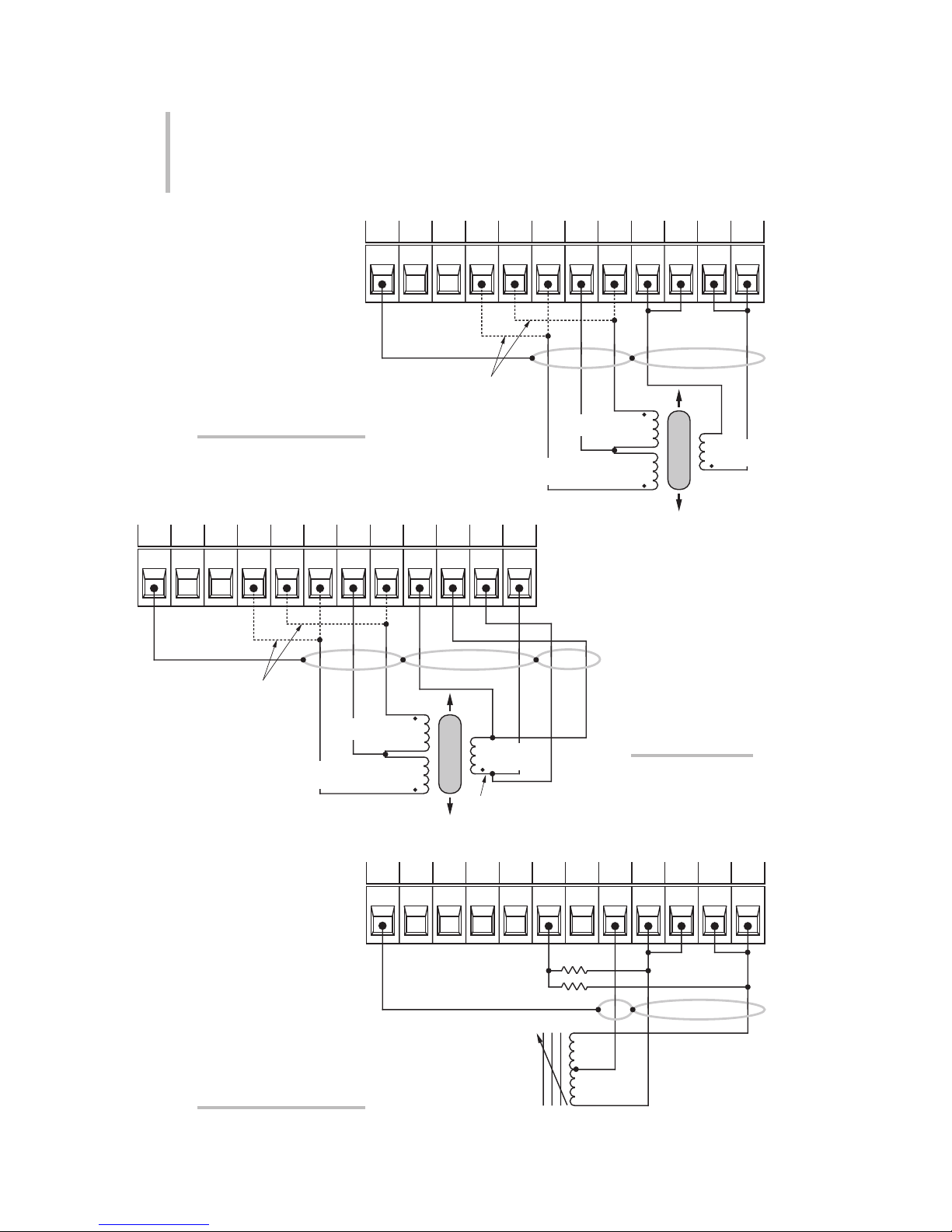
2.a.3 CONNECTING AN LVDT OR VARIABLE
RELUCTANCE TRANSDUCER TO THE MODEL 3530
With regard to transducer cabling for the Model 3530 LVDT Conditioner, please
note the following:
a. 5-wire LVDT cabling (Fig. 7(a)) or 3-wire variable reluctance transducer
cabling (Fig. 7(c)) is to be used when the cable is under 20 feet in length. In
this case, the +SENSE and –SENSE lines are tied to the corresponding EXCITATION lines at the CONDITIONER CONNECTOR.
7-wire LVDT cabling (Fig. 7(b)) or 5-wire variable reluctance transducer
cabling (Fig. 7(d)) is to be used when the cable is 20 feet or longer. In this
case, the +SENSE and –SENSE lines are tied to the corresponding EXCITATION lines at the transducer.
b. When wiring an LVDT transducer to the 3530, you should connect both series-
opposed secondary coils to the terminal labelled "CENTER WIRE," as shown
in Figs. 7(a) and 7(b).
c. NOTE THAT THERE ARE SPECIAL +SIGNAL AND –SIGNAL CONNECTIONS
FOR USE WITH LONG-STROKE LVDT'S (FULL-SCALE INPUT OF 0-1, 0-2, OR
0-4 VOLTS/VOLT).
Thus, to allow for the larger input voltages produced by such a sensor, you
would connect its +SIGNAL line to the terminal labelled "HI +SIG," instead of to
the "+SIG" terminal. Similarly, you would connect the –SIGNAL line to the terminal labelled "HI –SIG" instead of to the "–SIG" terminal.
2.a TRANSDUCER CONNECTIONS: MODEL 3530
Page 21
SETUP: CONNECTIONS AND POWERUP
–
SIG
+
SIG
CNTR
WIRE
+
SENS+EX
LVDT INPUT
–EX–
SENS
HI –
SIG
HI +
SIG
–SENSE
+SENSE
+EXCITATION
+SIGNAL
–EXCITATION
–SIGNAL
10K
10K
N/C
SHIELD
SHLD N/C
–
SIG
+
SIG
CNTR
WIRE
+
SENS+EX
LVDT INPUT
–EX–
SENS
HI +
SIG
–SENSE
+SENSE
–EXCITATION
+EXCITATION
+SIGNAL
–SIGNAL
PRIMARY
COIL
SECONDARY
COILS
Sec. 1
Sec. 2
CENTER
WIRE
HI –
SIG
N/C
SHIELD
SHLD N/C
For
Long-Stroke
LVDT's
–
SIG
+
SIG
CNTR
WIRE
+
SENS+EX
LVDT INPUT
–EX–
SENS
HI –
SIG
HI +
SIG
–SENSE
+SENSE
–EXCITATION
+EXCITATION
–SIGNAL
PRIMARY
COIL
Sec. 1
Sec. 2
CENTER
WIRE
For
Long-Stroke
LVDT's
SECONDARY
COILS
+SIGNAL
N/C
SHIELD
SHLD N/C
d. When wiring a variable reluctance transducer to the 3530, you must install a
10-kilohm "half-bridge completion" resistor between the –SIGNAL line and
each of the two EXCITATION lines, as shown in Figs. 7(c) and 7(d).
Fig. 7(a) Model 3530
Transducer Cabling:
5-Wire LVDT Cabling
(under 20 ft. in length)
2
Fig. 7(c) Model 3530
Transducer Cabling:
3-Wire Variable
Reluctance Cabling
(under 20 ft. in length)
Fig. 7(b) Model 3530
Transducer Cabling:
7-Wire LVDT Cabling
(20 ft. or longer)
2.a TRANSDUCER CONNECTIONS: MODEL 3530
2.3
Page 22
2
–
SIG
+
SIG
CNTR
WIRE
+
SENS+EX
LVDT INPUT
–EX–
SENS
HI –
SIG
HI +
SIG
–SENSE
+SENSE
+EXCITATION
+SIGNAL
–EXCITATION
SHIELD
–SIGNAL
10K
10K
N/CSHLD N/C
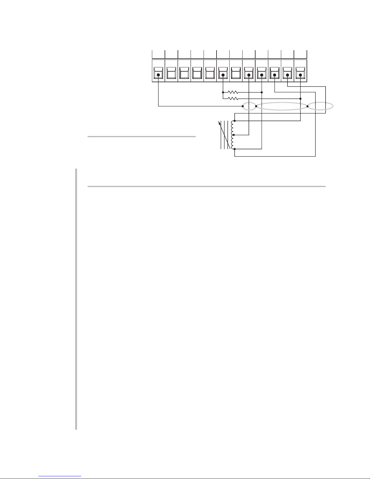
SETUP: CONNECTIONS AND POWERUP
Fig. 7(d) Model 3530
Transducer Cabling: 5-Wire Variable
Reluctance Cabling (20 ft. or longer)
2.a.4 CONNECTING A FREQUENCY
SOURCE TO THE MODEL 3540
Fig. 8(a) shows recommended cabling for connecting the Model 3540 Frequency Conditioner to a pulse transformer transducer with two-wire isolated wind-
ings (tachometer, turbine flowmeter, etc.). Fig. 8(b) shows the connection to a
transistor or logic-circuit driver, while Fig. 8(c) shows the connection to a "zero-
velocity" (i.e., true digital output) sensor. For a single-ended input, note that the
–SIG terminal should be tied to the SIG COM terminal, as shown in Fig. 8(b).
Note too that, when used with an open-collector type sensor—such as a zerovelocity sensor—a pull-up resistor of typically 10 kilohms is required between the
terminal to which the +SIGNAL line is tied and the +5V terminal, as shown in Fig.
8(c). For a zero-velocity sensor, the +SIGNAL line is to be tied to the +SIGA terminal to eliminate any DC offset (see below).
The Model 3540’s input channel is equipped with a capacitive-coupled input (0.1
µF). This special input may be used with either floating or grounded configurations if you require elimination of DC offset or suppression of high-frequency
noise. Figs. 8(d) and 8(e) show how these effects can be achieved.
Elimination of DC Offset—The 0.1-µF capacitive coupling can be used to eliminate any positive or negative DC offset that exists for the frequency signal. Simply connect the +SIGNAL line from the frequency source to the +SIGA terminal,
instead of to the normal +SIG terminal (see Fig. 8(d)). The capacitor is here in
series with the +SIGNAL input and allows only AC to pass.
Suppression of High-Frequency Noise—False triggering can sometimes occur,
especially at the low-frequency input range, because of stray pickup of frequencies outside the common-mode range. Capacitive coupling of the frequency
input to ground can in such cases serve to suppress unwanted signal noise.
Thus, if you find your frequency reading to be unacceptably unstable or "noisy,"
you should tie the +SIGA terminal to the SIG COM terminal, while maintaining the
normal +SIGNAL connection to the +SIG terminal (see Fig. 8(e)). With reference to
the suppression of high-frequency noise by grounding +SIGA, note that
• it is always recommended for magnetic-pickup sensors; and
• in general, it is NOT to be used with transducers that produce
active output (e.g., TTL logic drivers).
2.4
2.a TRANSDUCER CONNECTIONS: MODEL 3540
Page 23
SETUP: CONNECTIONS AND POWERUP
SHIELD
SHLD
–SIGNAL
+SIGNAL
–
+
EXCITATION
COM
SIG
SIG
–
SIG
+
FREQUENCY
SOURCE
SIGNAL INPUTS
SIGA
+
5V
–
COM
PWR
5V
+
SHIELD
SHLD
–SIGNAL
+SIGNAL
–
+
EXCITATION
COM
SIG
SIG
–
SIG
+
FREQUENCY
SOURCE
SIGNAL INPUTS
SIGA
+
5V
–
COM
PWR
5V
+
SHLD
EXCITATION
COM
SIG
SIG
–
SIG
+
SIGNAL INPUTS
SIGA
+
5V
–
COM
PWR
5V
+
+SIGNAL
SHLD
EXCITATION
COM
SIG
SIG
–
SIG
+
SIGNAL INPUTS
SIGA
+
5V
–
COM
PWR
5V
+
ZERO-VELOCITY SENSOR
+EXCITATION
+SIGNAL
–EXCITATION
SHIELD
10K
10K Pull-up Resistor (for
use with open-collector
sensor)
SHLD
EXCITATION
COM
SIG
SIG
–
SIG
+
SIGNAL INPUTS
SIGA
+
5V
–
COM
PWR
5V
+
+SIGNAL
2
Fig. 8(a) Model 3540 Transducer
Cabling: Differential (Floating)
Frequency Input
Fig. 8(b) Model 3540 Transducer
Cabling: Single-Ended (Grounded)
Frequency Input
Fig. 8(c) Model 3540
Transducer Cabling:
Input from a ZeroVelocity Sensor
Fig. 8(d) Model 3540 Transducer
Cabling for Elimination of DC Offset
Fig. 8(e) Model 3540 Transducer
Cabling for Suppression of HighFrequency Noise
2.a TRANSDUCER CONNECTIONS: MODEL 3540
2.5
Page 24
2
SHIELD
N/CSHLD
–SIGNAL
+SIGNAL
Reg. Power
Supply
(if required)
–
+
ANALOG
SIGNAL
SOURCE
Add wire for
floating input
POWER
OUT
SIGNAL
INPUT
± 40 MA MAX
COM
SIG
SIG
–
SIG
+
–12VCOM+12V
N/CSHLD
POWER
OUT
SIGNAL
INPUT
± 40 MA MAX
COM
SIG
SIG
–
SIG
+
–12VCOM+12V
SHIELD
+SIGNAL
–EXCITATION
2K to
10K
+EXCITATION
N/CSHLD
POWER
OUT
SIGNAL
INPUT
± 40 MA MAX
COM
SIG
SIG
–
SIG
+
–12VCOM+12V
SHIELD
+SIGNAL
–EXCITATION
+EXCITATION
DC-to-DC
LVDT
–SIGNAL
Tie the –SIG and SIG COM
terminals if a –SIGNAL wire from
the transducer is not available
SETUP: CONNECTIONS AND POWERUP
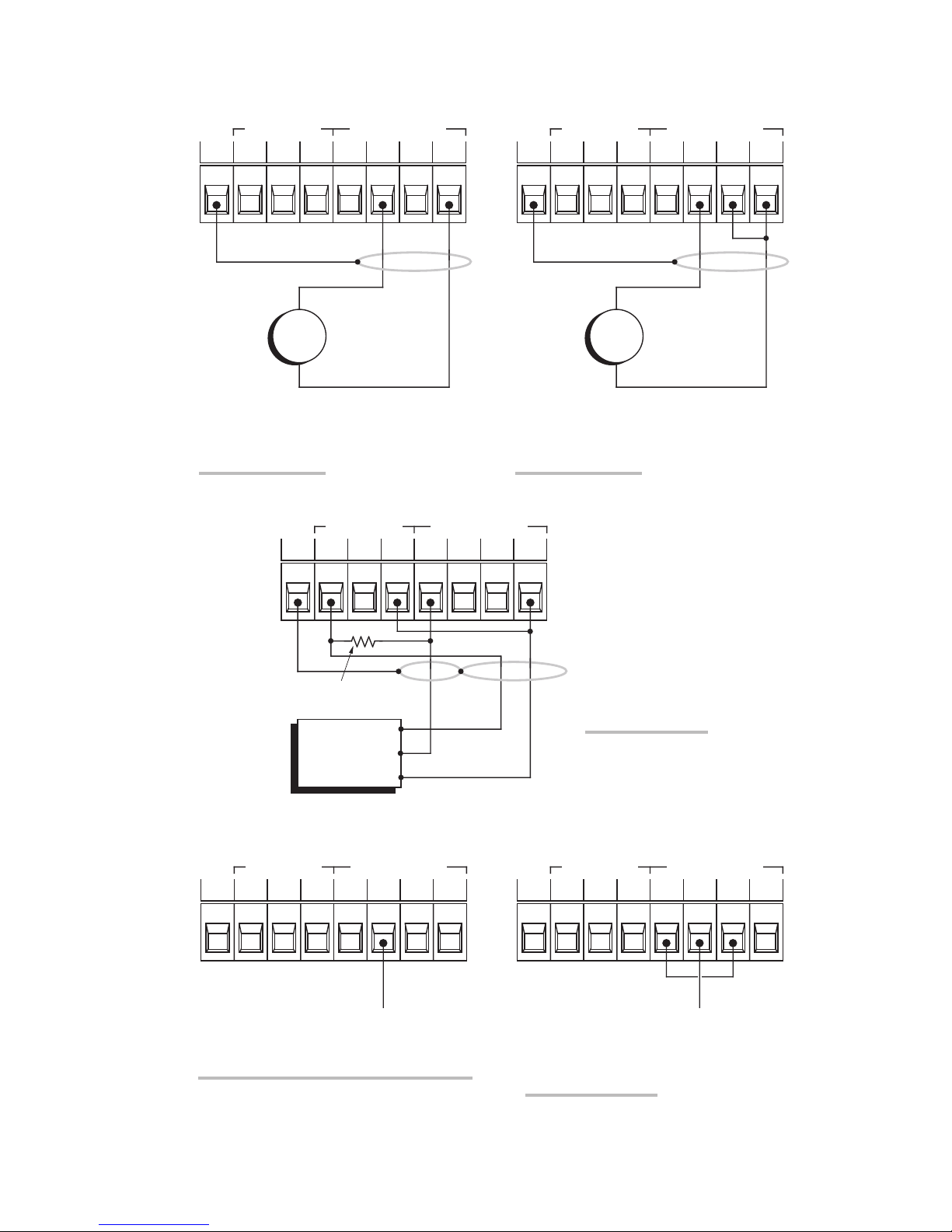
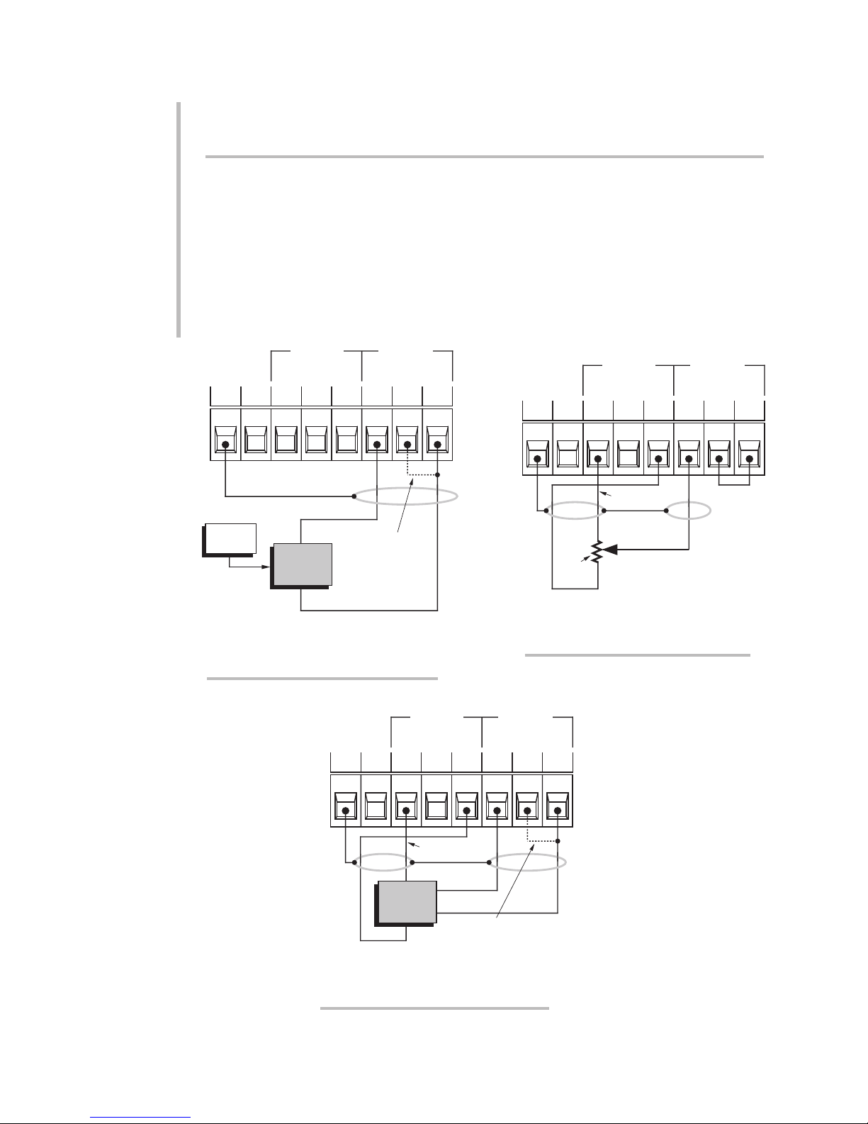
2.a.5 CONNECTING A VOLTAGE
SOURCE TO THE MODEL 3560
Fig. 9(a) gives standard cabling for connecting to the Model 3560 Voltage Conditioner a general ANALOG SIGNAL SOURCE, floating or grounded, with its own
power supply (if required); Fig. 9(b), for connecting an EXTERNAL ZERO-TO-FULLSCALE POTENTIOMETER with a resistance from 2 to 10 kilohms, using the instru-
ment's ±12-V excitation; and Fig. 9(c), for connecting an EXTERNAL DC-TO-DC
LVDT, again using the ±12-V excitation. As shown in Fig. 9(a), a floating input is to
be grounded by tying the transducer's –SIGNAL line to the SIG COM terminal.
When a –SIGNAL line from the transducer is not available, the –SIG and SIG COM
terminals should be connected by a jumper wire (as in Figs. 9(b) and 9(c)).
Fig. 9(a) Model 3560 Transducer
Cabling: General Voltage Source
2.6
2.a TRANSDUCER CONNECTIONS:MODEL 3560
Fig. 9(b) Model 3560 Transducer
Cabling: External Potentiometer
Fig. 9(c) Model 3560 Transducer
Cabling: External DC-to-DC LVDT
Page 25
SETUP: CONNECTIONS AND POWERUP
See Fig. 5(b)
–
SHLD
SHUNT CAL
CONTROL
STRAIN GAGE INPUT
SIG
+–
COM
SIG
+
EX
+
SENS
+
SENS
–
EXSENS
CAL–
SIGCOM
PWR
SHIELD
+SENSE
+EXCITATION
–EXCITATION
–SIGNAL
+SIGNAL
–SENSE
CAL
SENSE
See Fig. 5(b)
–
SHLD
SHUNT CAL
CONTROL
STRAIN GAGE INPUT
SIG
+–
COM
SIG
+
EX
+
SENS
+
SENS
–
EXSENS
CAL–
SIGCOM
PWR
SHIELD
+SENSE
+EXCITATION
–EXCITATION
–SIGNAL
+SIGNAL
–SENSE
CAL SENSE
UNCONNECTED WIRE
(PAIRED WITH "CAL SENSE")
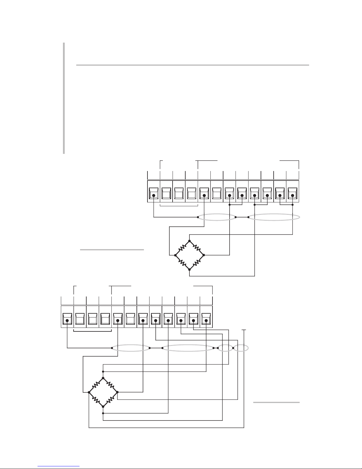
2.a.6 CONNECTING A DC STRAIN GAGE
TRANSDUCER TO THE MODEL 3570
Four-wire strain gage cabling (Fig. 10(a)) is to be used with the Model 3570 DC
Strain Gage Conditioner when the cable is under 20 feet in length. In this case,
the +SENSE and –SENSE lines are tied to the corresponding EXCITATION lines,
and also the CALIBRATION SENSE line to the +SIGNAL line, at the CONDITIONER
CONNECTOR.
Eight-wire strain gage cabling (Fig. 10(b)) is to used when the cable is 20 feet or
longer. In this case, the +SENSE and –SENSE lines are tied to the corresponding
EXCITATION lines, and the CALIBRATION SENSE line to the +SIGNAL line, at the
transducer. Note also the wire connected to the –SIGNAL line at the transducer,
but left unconnected at the instrument. This wire is to be paired with the CAL
SENSE line, as shown, for shielding purposes.
2
Fig. 10(a) Model 3570
Transducer Cabling:
4-Wire Cabling
(under 20 ft. in length)
Fig. 10(b) Model 3570
Transducer Cabling:
8-Wire Cabling
(20 ft. or longer)
2.a TRANSDUCER CONNECTIONS: MODEL 3570
2.7
Page 26
2
A
B
C
D
E
F
H
J
K
L
1
2
3
4
5
6
7
8
9
10
+SIGNAL
CONDITIONER CONNECTOR
–EXCITATION
+EXCITATION
–SIGNAL
–SENSE
+SENSE
CAL SENSE
SHIELD
Connector pins shown as viewed
from rear (cable) side of
connector.
Ground Lug
A
B
C
D
E
F
H
J
K
L
1
2
3
4
5
6
7
8
9
10
CONDITIONER CONNECTOR
+EXCITATION
+SENSE
SHIELD
Connector pins shown as viewed
from rear (cable) side of
connector.
Ground Lug
+SIGNAL
–EXCITATION
–SIGNAL
–SENSE
CAL SENSE
Unconnected wire
(Paired with "CAL SENSE")
SETUP: CONNECTIONS AND POWERUP
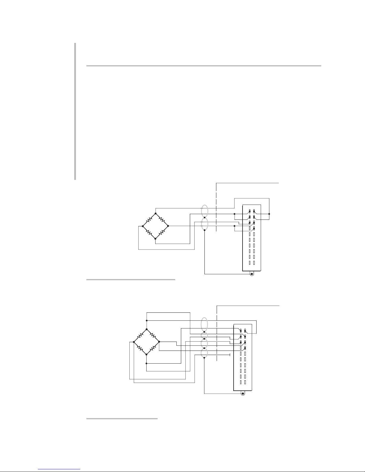
2.a.7 CONNECTING AN AC STRAIN GAGE
TRANSDUCER TO THE MODEL 3578
As shown in Fig. 2(a), the Model 3578 AC Strain Gage Conditioner's Analog
Input Board mates with a special CONDITIONER CONNECTOR. This connector
allows direct solder-terminal attachment of cable leads. The connector's internal
solder terminals are labelled 1 through 10 and A through L. The connector is
"keyed" by small plastic inserts embedded between certain terminal-pin pairs,
each of which matches a slot in the conditioner's Analog Input Board. This prevents the connector from being inadvertently attached upside-down.
Open the connector housing by removing the four screws that hold it together.
Secure the cable by means of one of the internal clamp bars.
The "shield" wire of the transducer cable should be soldered to the exposed terminal of the L-shaped GROUND LUG located under the head of one of the connector's two captive screws. This will ensure direct shield contact with the 3578’s
metal case.
Fig. 11(a) Model 3578
Transducer Cabling: 4-Wire
Cabling (under 20 ft. in length)
2.8
2.a TRANSDUCER CONNECTIONS: MODEL 3578
Fig. 11(b) Model 3578
Transducer Cabling: 8-Wire
Cabling (20 ft. or longer)
Page 27
SETUP: CONNECTIONS AND POWERUP
A
B
C
D
E
F
H
J
K
L
1
2
3
4
5
6
7
8
9
10
CONDITIONER CONNECTOR
–SENSE
+SENSE
SHIELD
External
SHUNT
CALIBRATION
RESISTOR
(UserSupplied)
+SIGNAL
A
B
C
D
E
F
H
J
K
L
1
2
3
4
5
6
7
8
9
10
CONDITIONER CONNECTOR
+EXCITATION
+SENSE
SHIELD
Connector pins shown as viewed
from rear (cable) side of
connector.
Ground Lug
+SIGNAL
–EXCITATION
–SIGNAL
–SENSE
A
D
C
B
CAL
(E)
Unconnected wire
(Paired with "LEBOW CAL")
LEBOW CAL
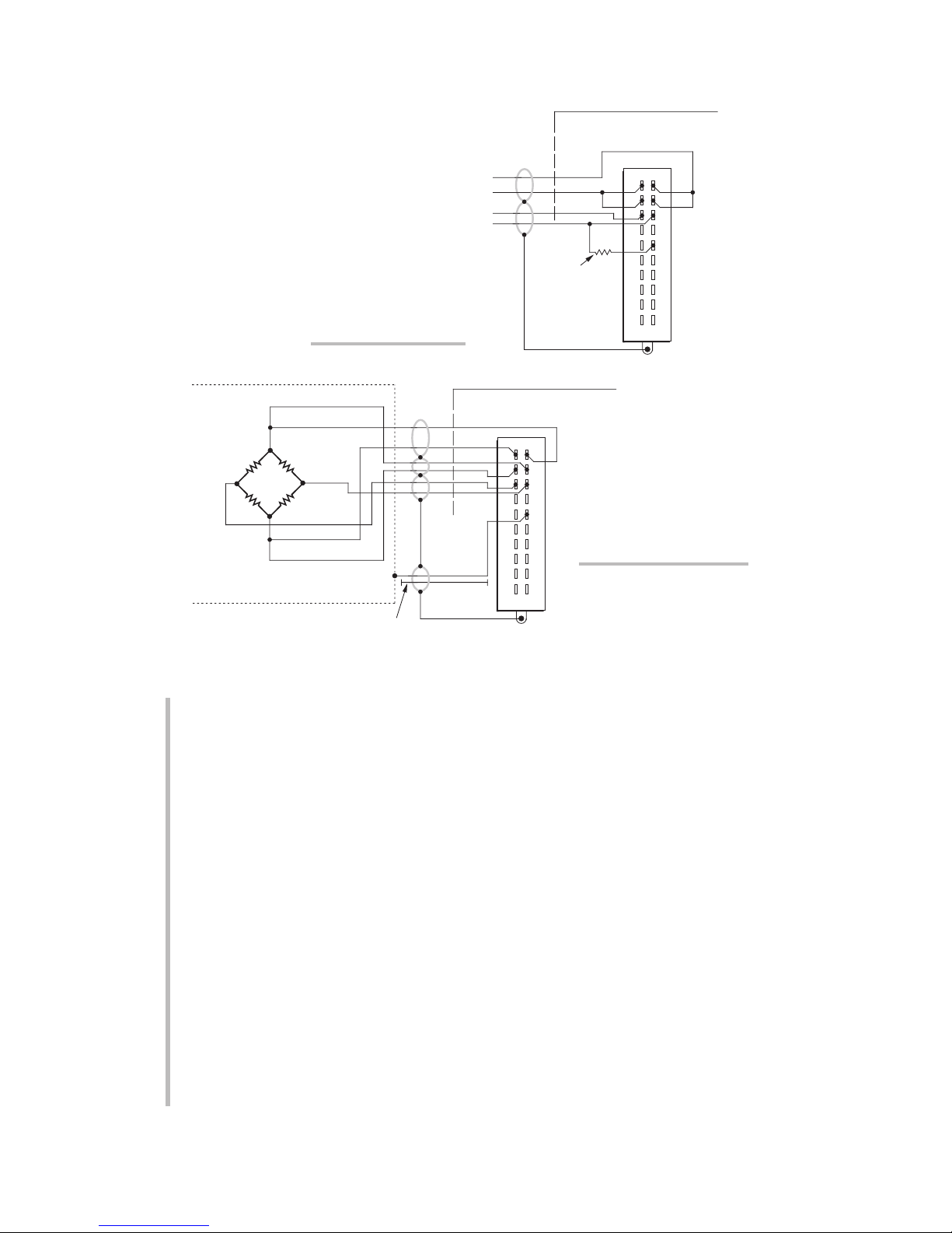
Fig. 11(c) Model 3578
Transducer Cabling:
Installation of User’s
External Shunt
Calibration Resistor
Fig. 11(d) Model 3578
Transducer Cabling: 8-Wire
Cabling to LEBOW 1600 SERIES
TRANSDUCER (ONLY)
2
Four-wire strain gage cabling (Fig. 11(a)) is to be used when the cable is under 20
feet in length.
The Model 3578 is equipped with an internal 59-KΩ, 0.1% calibration resistor for
the standard "shunt" calibration technique described in Section 4. If you wish to
use your own external shunt resistor, it should be tied between Pin 5 of the CONDITIONER CONNECTOR and the transducer's +SIGNAL line, as shown in Fig.
11(c). In this case, "CAL SENSE" (Pin 4) is not used.
With cabling under 20 feet in length, the +SENSE and –SENSE lines are tied to the
corresponding EXCITATION lines at the CONDITIONER CONNECTOR. Also, the
CALIBRATION SENSE line from Pin 4—or the optional external SHUNT RESISTOR
line from Pin 5—is tied to the +SIGNAL line at the CONDITIONER CONNECTOR.
Eight-wire strain gage cabling (Fig. 11(b)) is to used when the cable is 20 feet or
longer.* As before, you can install your own shunt calibration resistor between
Pin 5 and the +SIGNAL line, in which case Pin 4 is not used.
With cabling of 20 feet or over, the +SENSE and –SENSE lines are tied to the corresponding EXCITATION lines at the transducer. Also, the CALIBRATION SENSE
* NOTE: This cabling is to be used when connecting the Model 3578 to a Lebow 1800 Series
Transducer, regardless of cable length.
2.a TRANSDUCER CONNECTIONS: MODEL 3578
2.9
Page 28

2
SETUP: CONNECTIONS AND POWERUP
line from Pin 4—or the optional external SHUNT RESISTOR line from Pin 5—is tied
to the +SIGNAL line at the transducer. Note the wire connected to the –SIGNAL
line at the transducer, but left unconnected at the instrument. This wire is to be
paired with the CAL SENSE or SHUNT RESISTOR line for shielding purposes.
Special 8-wire cabling (shown in Fig. 11(d)) is required for connecting the 3578 to
a Lebow 1600 Series Transducer. The cable should be shielded in four pairs,
as shown in the figure, with the shield open at the transducer end. Also note that
• SENSE and EXCITATION lines should be tied at the transducer.
• The conditioner's Pin 5 ("LEBOW CAL") is to be connected to the "CAL" pin on
the Lebow sensor (Pin 4 is not used in this case).
• You should leave the last (extra) wire unconnected at both ends, and pair it
with the "LEBOW CAL" line for the fourth shield.
• THE MODEL 3578 MUST BE INTERNALLY SET TO "SIGNAL COMMON"
MODE. CONTACT THE FACTORY FOR PRECISE INSTRUCTIONS.
2.b RS-232 (“SINGLE-NODE”) CONNECTIONS
You should set the RS-232/485 Interface Port for RS-232 operation when you
want your 3500 Series instrument to communicate with a single computer, terminal, buffered printer, or other RS-232-C device. To do so, you need only MAKE
SURE THAT THE INSTRUMENT'S CURRENT NODE NUMBER IS "0" (ZERO). You
will be shown in Section 3.a.3 how to set the node number and other necessary
RS-232 communications parameters via the front-panel buttons.
If you did not order a specific RS-232-C Interface Cable with your 3500 Series
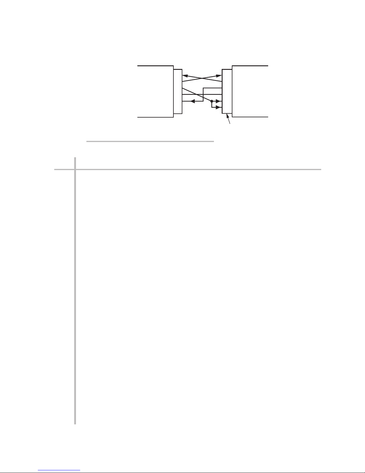
instrument, you will have to provide your own connection. Fig. 12 shows suggested cabling between the instrument and a computer, terminal, printer, etc., that
uses a 25-Pin RS-232-C Connector. FOR MAXIMUM DATA-TRANSFER SPEED
AND ACCURACY, A "FULL HANDSHAKE" INTERCONNECTION IS GENERALLY
RECOMMENDED (Fig. 12(a)). However, cabling is also given for "INCOMING
HANDSHAKE ONLY" and "NO HANDSHAKE" situations (Figs. 12(b) and 12(c),
respectively). Following RS-232-C conventions, the device at each end of the
interface is seen as "DATA TERMINAL EQUIPMENT (DTE)."
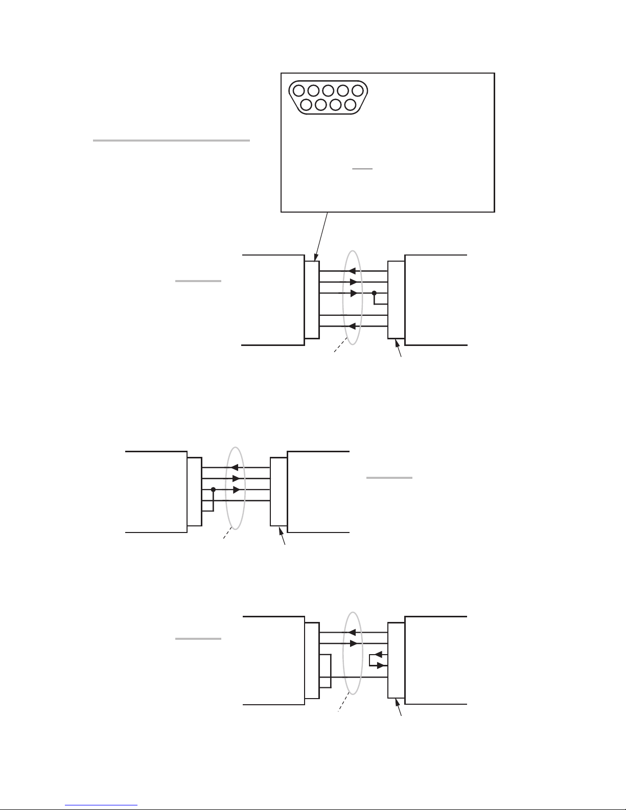
Fig. 13 shows suggested cabling between a 3500 Series instrument and a computer, terminal, printer, etc., that uses a 9-Pin D-Subminiature Connector for its RS232-C interface (such as an IBM PC/AT).
Please note that the cabling in Figs. 12 and 13 is by no means definitive. In all
cases, you should carefully study the literature accompanying the specific RS232-C device you wish to connect to your instrument, to determine the cable
arrangement that will create the "handshake" you need (if any). On some devices,
for example, the DATA TERMINAL READY (DTR) signal may have a different
name (such as NOT BUSY) and may even appear on a pin other than No. 20 or
No. 4.
2.10
2.b RS-232 (“SINGLE-NODE”) CONNECTIONS
Page 29
SETUP: CONNECTIONS AND POWERUP
Computer
or other RS-232-C Device
25-Pin RS-232-C
Connector
2
3
4
5
8
2
3
5
6
7
20
RECEIVE
TRANSMIT
DTR
COMMON
CTS
TRANSMIT
RECEIVE
CTS
DSR
COMMON
DTR
FULL HANDSHAKE
(RECOMMENDED)
*
* Required for IBM and IBM-compatible computers.
DATA (RS-485)
RECEIVE (RS-232)
TRANSMIT (RS-232)
DATA TERMINAL READY (RS-232)
COMMON
DATA (RS-485)
+12 V (RS-485)
CLEAR TO SEND (RS-232)
SHIELD
RS-232/485 Interface
Connector—Male
(see Fig. 2)
1
2345
6
789
1
2
3
4
5
6
7
8
9
Pin No. Function
3500 Series
Instrument
25-Pin RS-232-C
Connector
2
3
4
5
8
2
3
5
7
20
RECEIVE
TRANSMIT
DTR
COMMON
CTS
TRANSMIT
RECEIVE
CTS
COMMON
DTR
INCOMING HAND-
SHAKE ONLY
Computer
or other RS-232-C Device
3500 Series
Instrument
25-Pin RS-232-C
Connector
2
3
4
5
8
2
3
4
5
7
20
RECEIVE
TRANSMIT
DTR
COMMON
CTS
TRANSMIT
RECEIVE
RTS
CTS
COMMON
DTR
NO HANDSHAKE
Computer
or other RS-232-C Device
3500 Series
Instrument
Fig. 12 Suggested RS-232-C
Interface Connections
(to 25-Pin RS-232-C Connector)
Fig. 12(a)
2
Fig. 12(c)
Fig. 12(b)
2.b RS-232 (“SINGLE-NODE”) CONNECTIONS
2.11
Page 30
2
9-Pin RS-232-C
Connector
2
3
4
5
8
2
3
4
5
6
8
RECEIVE
TRANSMIT
DTR
COMMON
CTS
RECEIVE
TRANSMIT
DTR
COMMON
DSR
CTS
Computer
or other RS-232-C Device
SETUP: CONNECTIONS AND POWERUP
Fig. 13 Suggested RS-232-C Interface
Connections (to 9-Pin RS-232-C Connector)
2.c RS-485 (“MULTINODE NETWORK”) CONNECTIONS
You can also set a 3500 Series instrument's RS-232/485 Interface Port for RS-485
intercommunications with a multidrop network of up to 99 independent Daytronic
signal conditioning instruments (3500 Series, 4000 Series with “N” Option, and/or
5000 Series)—all controlled by a supervisory computer with RS-232-C I/O. To do
so, YOU MUST ASSIGN THE 3500 INSTRUMENT A UNIQUE NONZERO NODE
NUMBER. You will be shown in Section 3.a.4 how to set the node number and
other necessary RS-485 communications parameters via the front-panel buttons.
IMPORTANT: BEFORE NETWORK INTERCONNECTIONS ARE ESTABLISHED,
YOU SHOULD SET UP EACH 3500 SERIES NETWORK "NODE" INDIVIDUALLY, BY
MEANS OF THE SETUP PROCEDURES GIVEN IN SECTIONS 3 AND 4.
While it is possible to make separate network "branches" issue from a single
node, such an arrangement can lead to less than optimum signal-to-noise ratio
because of unwanted reflections over interface lines. A strictly linear configuration like that shown in Fig. 14(a) is therefore highly recommended.
For proper conversion of interface levels, you must attach a Model 5E485
RS232-to-RS485 Adaptor to the computer's RS-232-C port, via the Model 5E25
DB25 Male-to-Female Converter, as shown in Fig. 14(a).* The adaptor’s RS-
485 Interface Port should then connect directly to the RS-232/485 Interface Port
of the first network node—which should be a 3500 Series instrument—via the
cabling given in Fig. 14(b). Note that the +12-V supply of the first node (when it is
a 3500 instrument) is used to power the Model 5E485, as shown in Fig. 14(b).**
Fig. 14(c) shows the pin-to-pin cabling to be used between each pair of adjacent
3500 instrument nodes, or between a 3500 node and an adjacent 4000 Series
node. Interconnections between a 3500 or 4000 node and a separately powered
5000 node are shown in Fig. 14(d).
* The Model 5E25 is not necessary when the computer is equipped with a Model PC-HSICA
High-Speed Serial Interface Card. Also, you may use your own RS-232-to-RS-485 converter
in place of the Model 5E485, if desired. Converter connections will depend on whether there
are separate "XMIT" and "RCV" pairs or a single "485 DATA" pair. Contact the factory for
instructions.
** If the network contains one or more 5000 Series instrument nodes, a separate power source
of 10 to 40 V-DC (nominal 24 V-DC recommended) is required to power both the 5E485 and
the 5000 nodes—in which case the +12-V pin on every 3500 node should not be used. See any
5000 instrument instruction manual for details.
2.12
2.c RS-485 (“MULTINODE NETWORK”) CONNECTIONS
Page 31

SETUP: CONNECTIONS AND POWERUP
100 Ω
0.0047 µf
RS-485 Terminator
(for chains over 500 ft.)
Computer 25-Pin
RS-232-C Port
Model 5E485
RS232-to-RS485
Adaptor
Model 5E25
Male-to-Female
Converter*
Not required with
Model PC-HSICA
High-Speed Serial
Interface Card.
Node 1
COMMON
485 DATA
485 DATA
SHIELD
4-pin RS-485 Interface
& DC Power Port
Node RS-485 Interface
Port or Computer
Interface Port in RS-485
Communications Mode
For cabling,
see Fig. 14(b)
For cabling,
see Fig. 14(c)
Node 2
Node 3
*
3500 Series
Instrument
2
Fig. 14(a) Connections for a Network of Three Instrument Nodes (where the first is a 3500 Series instrument)
For RS-485 communications, the relevant pins of the RS-232/485 Interface Port
are as follows:
Pin No. Function
1 485 DATA
5 COMMON (GND)
6 485 DATA
7 +12 V
9 SHIELD
RS-485 interconnections require Belden 8162 Datalene 100-Ω shielded cable (or
equivalent). THE INDICATED SHIELDING IS VERY IMPORTANT AND SHOULD BE
FOLLOWED CLOSELY.
For network chains of over 500 feet, the RS-232/485 Interface Port of the last
node in the sequence should be "terminated" by means of a 0.0047-µf capacitor
and a 100-Ω resistor across the two "DATA" terminals (again, see Fig. 14(a)).
2.c RS-485 (“MULTINODE NETWORK”) CONNECTIONS
2.13
Page 32

2
+10 to 40 V
PWR COM
485 DATA
485 DATA
COMMON
485 DATA
485 DATA
Shield
For RS-485, use Belden 8162 Datalene
100- Shielded Twisted Pairs or other
cable intended for EIA RS-422/485
SHIELD
RS-485 Interface Port
(Model 5E485)
RS-232/485 Interface Port
(3500 Series Instrument)
+12 V
COMMON
485 DATA
485 DATA
COMMON
485 DATA
485 DATA
Shield
For RS-485, use Belden 8162 Datalene
100- Shielded Twisted Pairs or other
cable intended for EIA RS-422/485
SHIELD SHIELD
RS-232/485 Interface Port
(3500 or 4000 Series Instrument)
RS-232/485 Interface Port
(3500 or 4000 Series Instrument)
COMMON
485 DATA
485 DATA
+10 to 40 V
PWR COM
485 DATA
485 DATA
Shield
For RS-485, use Belden 8162
Datalene 100- Shielded
Twisted Pairs or other cable
intended for EIA RS-422/485
SHIELD
+
–
Power
Supply
See 5000 Instrument
Instruction Manual
RS-232/485 Interface Port
(3500 or 4000 Series Instrument)
RS-485 Interface Port
(5000 Series Instrument)
SETUP: CONNECTIONS AND POWERUP
Fig. 14(b) RS-485 Cabling Between the Model 5E485 and
the FIRST Network Node (if it is a 3500 Series instrument)
Fig. 14(c) RS-485 Cabling Between
Successive 3500 or 4000 Instrument Nodes
2.14
2.c RS-485 (“MULTINODE NETWORK”) CONNECTIONS
Fig. 14(d) RS-485 Cabling Between a 3500 or
4000 Instrument Node and a 5000 Instrument Node
Page 33

SETUP: CONNECTIONS AND POWERUP
Analog Output
Analog Input
+PEAK A/D
Analog Output
Programming Pins
(see Fig. 2)
A
Berg-Pin Jumper
(connect one pair only)
BCD
ABC
Fixed Analog Filter:
Model 3530 LVDT Conditioner: 100 Hz
Model 3560 Voltage Conditioner: 2000 Hz
Model 3570 DC Strain Gage Conditioner: 2000 Hz
Model 3578 AC Strain Gage Conditioner: 20 Hz
Selectable Analog Filter:
5/10/20 Hz
This diagram does not apply to the Models
3510 and 3540, which do not have Analog
Output Programming Pins.
2.d ANALOG OUTPUT CONNECTIONS
As indicated in Fig. 15, the ±5-V analog output signal of the Model 3530 LVDT
Conditioner, Model 3560 Voltage Conditioner, Model 3570 DC Strain Gage
Conditioner, or Model 3578 AC Strain Gage Conditioner may represent the
state of the conditioned input (A) after the FIXED ANALOG FILTER; (B) after analog
peak capture; or (C) after the SELECTABLE ANALOG FILTER (5/10/20 Hz for each
of these conditioners).* Each unit is initially set at the factory to source the analog
output after the FIXED ANALOG FILTER (Point A). To select a different source
point for any of these conditioners, you should
1. First turn OFF the unit and disconnect the power cord.
2. Remove the screw(s) holding the rear plate that covers the ANALOG OUTPUT
PROGRAMMING PINS (see Fig. 2(a) or 2(b)).**
3. Using needle-nose pliers, pull out the single Berg-Pin jumper and reposition it
on the pair of pins corresponding to the desired source (A, B, or C—again, see
Fig. 15). The pins labelled D are not currently used.
4. Replace the cover and reactivate the unit.
2
Fig. 15 Analog Output Programming Pins
* For the Model 3540 Frequency Conditioner, the SELECTABLE ANALOG FILTER is 2.5/5/10 Hz;
for the Model 3510 Thermocouple Conditioner, there is no SELECTABLE ANALOG FILTER. The
3510’s ANALOG OUTPUT is taken directly from the DIGITAL/ANALOG CONVERTER; the 3540’s
ANALOG OUTPUT is always taken from souce "C" in the figure.
** The Model 3578 AC Strain Gage Conditioner has only one screw; the others have two.
2.d ANALOG OUTPUT CONNECTIONS
2.15
Page 34

2
EXTERNAL
DEVICE
+
–
Signal
Common
Signal
Shield
GND OUT
ANALOG
+5V
PWR
COM
This terminal not
currently used
SETUP: CONNECTIONS AND POWERUP
Fig. 16 shows how an external device connects to the ANALOG OUTPUT CONNECTOR on the rear of the conditioner, including the Models 3510 and 3540. The
output is single-ended, and returns to "SIGNAL COMMON" (i.e., GROUND).
For offsetting and scaling of the ANALOG OUTPUT, see Section 3.a.7. The fre-
quency characteristics and step-response settling time of the output will depend
on which pair of programming pins are jumpered. For details, see Appendix A.
Fig. 16 Analog Output
Connections
(ALL Conditioners)
2.e LOGIC INPUT/OUTPUT CONNECTIONS
The rear LOGIC I/O CONNECTOR is shown in Figs. 2 and 5(a). It has eight
labelled TTL/CMOS-compatible I/O terminals (one of which is normally unused),
plus a LOGIC REFERENCE terminal (+5 V) and a GROUND terminal (COM). In the
standard logic configuration described in Section 1.f and Appendix F, the first
three I/O terminals (left to right) are logic outputs, while the last four are logic
inputs. For the Model 3570 DC Strain Gage Conditioner (only), two logic inputs
("+" and "–") are also provided on the Analog Input Connector, for control of shunt
calibration—see Fig. 5(b). For complete logic-signal specifications, see Appendix
A.
Fig. 17 shows how to wire
a. negative-true logic INPUT to a given terminal from external switch contacts;
b. negative-true logic INPUT to a given terminal from an active TTL logic system
and open-collector logic OUTPUT from a given terminal to an active TTL logic
system;
c. negative-true logic INPUT to a given terminal from an INPUT CONTROL
BLOCK and open-collector logic OUTPUT from a given terminal to an isolated
POWER CONTROL BLOCK.
d. open-collector logic OUTPUT from a given terminal to drive an external relay
or TRIAC controller.
2.16
2.e LOGIC INPUT/OUTPUT CONNECTIONS
Page 35

SETUP: CONNECTIONS AND POWERUP
Logic I/O Connector
COM
+5 V
Logic Input*
. . .
. . .
OPEN = LOGIC 0
CLOSED = LOGIC 1
Also includes "+" and "–" Calibration
Inputs for the Model 3570 DC Strain Gage
Conditioner (ONLY)—see Fig. 5(b).
*
COM
+5 V
Logic Input*
. . .
. . .
Logic Output
. . .
TTL or CMOS
+5
+5
Logic I/O Connector
Also includes "+" and "–" Calibration
Inputs for the Model 3570 DC Strain Gage
Conditioner (ONLY)—see Fig. 5(b).
*
Input
Control
Block
+
–
Logic I/O Connector
COM
+5 V
Logic Input*
. . .
. . .
Logic Output
. . .
Power
Control
Block
+
–
NOTE THAT THE
POWER CONTROL
BLOCK IS ENERGIZED
IN THE
TRUE
STATE
Also includes "+" and "–" Calibration
Inputs for the Model 3570 DC Strain Gage
Conditioner (ONLY)—see Fig. 5(b).
*
Fig. 17(a) Logic I/O
Connections: Input
from External Switch
Fig. 17(b) Logic I/O
Connections:
External TTL Logic
2
Fig. 17(c) Logic I/O
Connections:
External Controller
* Also includes "+" and "–" Calibration Inputs for the Model
3570 DC Strain Gage Conditioner (ONLY)—see Fig. 5(b).
2.e LOGIC INPUT/OUTPUT CONNECTIONS
2.17
Page 36

2
Logic I/O Connector
COM
+5 V
. . .
Logic Output
. . .
Coil
Resistance
> 500
SETUP: CONNECTIONS AND POWERUP
Fig. 17(d) Logic
I/O Connections:
Output to
External Relay
2.f POWERUP
Accepting a line voltage from 90 to 265 V-AC (50-400 Hz; 10 W max), your 3500
Series instrument will automatically sense the power input level and adjust its
internal regulator accordingly. THEREFORE, YOU NEED NOT SET THE INSTRUMENT FOR NOMINAL 110-V OR 220-V OPERATION.
IN THE EVENT OF AN APPARENT POWER-SUPPLY FAILURE, FIRST CHECK THE
0.5-AMP (250-V) BUSS FUSE LOCATED ON THE REAR PANEL (see Fig. 2). WHEN
REPLACING A "BLOWN" FUSE, ALWAYS INVESTIGATE THE CAUSE OF OVERLOAD BEFORE REACTIVATING THE INSTRUMENT.
To change the fuse, use a screwdriver to turn the fuse slot counterclockwise, and
the fuse holder will spring out.
The 6-foot, three-conductor power cord supplied with the unit plugs into the rear
AC POWER CONNECTOR. The offset pin on the power connector is ground.
THE INSTRUMENT MUST BE PROPERLY GROUNDED. To safely operate from
a two-contact outlet, use a 3-prong-to-2-prong adaptor and connect the green
pigtail on the adaptor to earth ground.
Since the presence of electrical noise can affect the ultimate integrity of your
data, the noise level should be suppressed as much as possible. In particular,
care should be taken to avoid utility-line problems that can interfere with or possibly even damage sensitive microprocessor-based equipment. Such noise can
also be generated by electrical motors, relays, and motor control devices.
While your instrument has internal circuitry to protect it from overvoltage transients and mild EMI, a clean line is still very desirable. No protection is provided
against dropout longer than 8 milliseconds or brownout below 90 volts. Depending on your line conditions, a number of protective devices are available (isolators, regulators, uninterruptible power supplies, etc.).
The ON/OFF switch is also located on the rear panel (see Fig. 2). When you
powerup the unit, you will observe the following sequence of events:
2.18
2.f POWERUP
Page 37

SETUP: CONNECTIONS AND POWERUP
• The entire LCD (buttons and digital display) will be turned momentarily ON
and OFF.
• The number "88888" will be displayed.
• The display will show either EPASS or EFAIL, following a checksum per-
formed on the EEPROM where program parameters are stored. If EFAIL
appears, it means that there is a difference between the calculated checksum
and the stored checksum. IN THE EVENT OF AN "EFAIL" MESSAGE, CONTACT THE FACTORY CUSTOMER SERVICE DEPARTMENT FOR INSTRUCTIONS.
• The display will show either rPASS or rFAIL, following a modified "walking bit"
test performed on the RAM chip. If rFAIL appears, it probably means either
that a RAM write did not take or that a write to one location affected another
byte of the RAM. IN THE EVENT OF AN "rFAIL" MESSAGE, CONTACT THE
FACTORY CUSTOMER SERVICE DEPARTMENT FOR INSTRUCTIONS.
• The display will show either cPASS or cFAIL, following a checksum per-
formed on the code PROM. If cFAIL appears, it means that the calculated
checksum was different from the stored checksum. IN THE EVENT OF A
"cFAIL" MESSAGE, CONTACT THE FACTORY CUSTOMER SERVICE DEPARTMENT FOR INSTRUCTIONS.
• The instrument model number will be displayed.
2
• The instrument software version will be displayed.
• "Live" numeric data will be displayed.
2.f POWERUP
2.19
Page 38

2.20
This page intentionally blank.
Page 39

SETUP: INSTRUMENT CONFIGURATION
3.a CONFIGURING THROUGH THE FRONT PANEL
3.a.1 ENTERING AND EXITING SETUP MODE
Your 3500 Series instrument's "setup configuration" can be fully established via
the front-panel push buttons—including the NUMERIC BUTTONS described in
Section 1.e. For configuration setup by means of MNEMONIC COMMANDS
issued to the instrument through its RS-232/485 Interface, see Section 3.b, below.
When you press
SET UP
you will first be asked for the current SECURITY CODE if a nonzero code has
already been specified. If it has not, you will be given a chance to enter one (see
below for the full procedure).
Once the correct nonzero security code has been entered (if called for) and you
have either changed the code or kept it as it is, the "Setup" display shown in Fig.
1(b) will appear. Note that the limit status indicators are no longer "live." They will
be updated, however, each time the LCD display changes.
Once in the "Setup" display, you can press any of the illuminated buttons and follow the steps given below to define the pertinent setup parameter(s). There is no
necessary setup sequence.
3
To exit SETUP MODE while the "Setup" display (Fig. 1(b)) appears, just press the
SETUP button again. If no setup parameters have been changed since you last
entered SETUP MODE, you will return immediately to the RUN-TIME ("live" data)
MODE. If, however, one or more setup parameters have been changed, the new
parameter value(s) will now be automatically saved. The unit will tell you this by
displaying the word "SAVING" for a few seconds:
You will then be returned to RUN-TIME ("live" data) mode with the
new setup configuration fully in effect.
If you press SETUP while within a given setup-button sequence ("COM,"
"RANGE," "CAL," etc.), you will return to the "Setup" display (Fig. 1(b)). You can
now either choose another setup button or exit SETUP MODE altogether by
pressing SETUP once again. If you haven't changed any setup values since you
last entered SETUP MODE, you will immediately return to a "live" data display. If
you have made changes, these will be saved before you return to "live" data.
In general, keeping your finger on a given setup button (COM, RANGE, CAL, FIL-
TER, etc.) will cycle you through all pertinent setup parameters. When you come
to the one you want to view and edit, just press ENTER to see that parameter's
existing value.
REMEMBER: AFTER CHANGING THE DISPLAYED VALUE OF A GIVEN SETUP
PARAMETER, YOU MUST PRESS
ENTER
3.a CONFIGURING THROUGH THE FRONT PANEL
3.1
Page 40

3
SETUP: INSTRUMENT CONFIGURATION
IN ORDER TO REGISTER THE CHANGE. IF YOU ONLY PRESS SETUP AFTER
CHANGING A SETUP VALUE, YOU WILL RETURN TO THE "SETUP" DISPLAY
WITHOUT HAVING ACTUALLY "ENTERED" THE CHANGE.
ALSO PLEASE NOTE: IF YOU ATTEMPT TO ENTER AN OUT-OF-RANGE OR OTHERWISE UNACCEPTABLE VALUE FOR A GIVEN SETUP PARAMETER, THE UNIT
WILL DISPLAY AN ERROR NUMBER, SUCH AS
If this occurs, refer to the ERROR-CODE TABLE in Appendix C. Note that the
ERROR-NUMBER will remain on display until you press the ENTER or SETUP button.
3.a.2 SECURITY CODE
If a nonzero SECURITY CODE has not already been entered, the operator will be
given the chance to do so as soon as the SETUP key is pressed. The unit will
ask:
If you do not want to enter a nonzero code at this time, just press SETUP again
and the "Setup" display (Fig. 1(b)) will appear. To enter a new code,
a. Press
ENTER
The current security code will be displayed (INITIALLY, THIS IS "0" FOR "NO
CODE").
b. Use the NUMERIC BUTTONS as discussed in Section 1.e, above, to display
any integral number from 1 through 98.
WARNING!
BE SURE TO WRITE DOWN THE NUMBER YOU SELECT AS YOUR SECURITY
CODE, SO THAT YOU DON'T FORGET IT. ONCE YOU PRESS ENTER, THERE IS
NO WAY TO INTERROGATE THE 3500 INSTRUMENT FOR THIS NUMBER,
EXCEPT BY A SECURITY CODE (SCD) COMMAND APPLIED THROUGH THE RS232/485 INTERFACE PORT (see Section 3.b, below). NOTE, HOWEVER, THAT
THE PROPER COMMUNICATIONS PROTOCOL MUST ALREADY BE ESTABLISHED IN ORDER FOR THE UNIT TO RECOGNIZE AND RESPOND TO THIS COMMAND. UNTIL SUCH COMMUNICATIONS HAVE BEEN SET UP, THE ONLY
ACCESS YOU WILL HAVE TO THE EFFECTIVE SECURITY CODE WILL BE YOUR
OWN MEMORY—AND WITHOUT THIS CODE, YOU ARE PROHIBITED FROM MAKING ANY SETUP CHANGES VIA THE FRONT PANEL, INCLUDING COMMUNICATIONS PROTOCOL!
c. Press ENTER once again. The "Setup" display (Fig. 1(b)) will appear. From
now on, you will have to enter the number that has just been specified in order
to enter SETUP MODE. Once in SETUP MODE, however, you can easily
change the existing code, as explained below.
3.2
3.a CONFIGURING THROUGH THE FRONT PANEL
Page 41

SETUP: INSTRUMENT CONFIGURATION
If a nonzero SECURITY CODE is already in effect, the operator will be asked to
enter it whenever the SETUP key is pressed:
The procedure for entering the existing code is as follows:
d. Press
ENTER
A zero will be displayed.
e. Use the NUMERIC BUTTONS to display the current security code.
f. Press ENTER again. If an incorrect code has been entered, you will simply
return to the "live" data display. To re-enter the (correct) code, you must again
press SETUP, followed by ENTER.
g. If the correct code has been entered, you will be given a chance at this time to
change it. The display will show Sc=?. If you want to change the code, follow
Steps a through c, above. If you don't want to change the code, press the
SETUP key to invoke the "Setup" display.
3
3.a.3 RS-232 COMMUNICATIONS PARAMETERS: COM KEY
PLEASE NOTE: FOR PROPER DATA INTERCHANGE BETWEEN THE 3500
INSTRUMENT AND A SINGLE CONNECTED RS-232-C COMPUTER, TERMINAL,
PRINTER, OR OTHER DEVICE TO OCCUR,
• THE INSTRUMENT SHOULD BE SET TO A NODE NUMBER OF "0," AND
• THE INSTRUMENT’S RS-232/485 INTERFACE MUST BE SET TO CONFORM
EXACTLY WITH THE PROTOCOL STIPULATED BY THE CONNECTED DEVICE.
To set the RS-232-C protocol,
a. Once you are in SETUP MODE, press the button labelled
COM
The unit will display the word "BAUD":
b. To display the current BAUD RATE setting, press
ENTER
If you don't want to display the baud rate, press COM again and proceed to
Step e.
c. To change the baud rate, you can cycle forwards or backwards through the
allowed settings (300 through 153.6K) by pressing the top or bottom segment,
respectively, of any digit display (even if it is blank).
3.a CONFIGURING THROUGH THE FRONT PANEL
3.3
Page 42

3
SETUP: INSTRUMENT CONFIGURATION
d. When the desired baud rate appears, press ENTER to return to the "BAUD"
display. Then press COM. The unit will display "DATA" (for "NUMBER OF
DATA BITS"):
e. To display the current data-bits setting, press ENTER. If you don't want to dis-
play the number of data bits, press COM again and proceed to Step h.
f. To change the data-bits setting, you can toggle between "7" and "8"—the only
allowable values—by pressing the top or bottom segment of the displayed
digit.
g. When the desired number of data bits appears, press ENTER and then COM.
The unit will display "STOP" (for "NUMBER OF STOP BITS"):
h. To display the current stop-bits setting, press ENTER. If you don't want to dis-
play the number of stop bits, press COM again and proceed to Step k.
i. To change the stop-bits setting, you can toggle between "1" and "2"—the only
allowable values—by pressing the top or bottom segment of the displayed
digit.
j. When the desired number of stop bits appears, press ENTER and then COM.
The unit will display "PAR" (for PARITY):
k. To display the current parity setting, press ENTER. If you don't want to display
the parity, press the COM button again and proceed to Step n.
l. To change the parity setting, you can cycle forwards or backwards through
the allowed settings by pressing the top or bottom segment, respectively, of
any digit display (even if it is blank). The four parity settings are
— where the total number of "1's" in each transmitted charac-
ter is ODD
— where the total number of "1's" in each transmitted charac-
ter is EVEN
— where the parity bit is always present, but always ZERO
— for NO parity bit
m. When the desired parity setting appears, press ENTER to return to the "PAR"
display. Then press COM. The unit will display "NODE" (for "NODE NUMBER"):
3.4
3.a CONFIGURING THROUGH THE FRONT PANEL
Page 43

SETUP: INSTRUMENT CONFIGURATION
n. To display the current node-number setting, press ENTER. If you don't want
to display the node number, press COM again and proceed to Step q.
IMPORTANT: FOR RS-232-C COMMUNICATIONS, THE NODE NUMBER MUST
REMAIN AT THE INITIAL SETTING OF ZERO ("00"). For configuration of RS-485
(MULTINODE NETWORK) communications, see Section 3.a.4, below.
IMPORTANT: IF YOU HAVE SWITCHED THE INSTRUMENT FROM "RS-232" TO
"RS-485" MODE OR VICE VERSA—I.E., IF YOU HAVE CHANGED THE NODE NUMBER FROM "0" TO A NONZERO VALUE OR VICE VERSA—YOU WILL HAVE TO
RECYCLE INSTRUMENT POWER BEFORE THE NEW MODE SETTING CAN GO
INTO EFFECT.
o. If the node number is already "00," you should leave it there by pressing COM
and proceeding to Step q. If the current node number is not "0," you should
change it to zero by pressing the bottom segment of each nonzero digit until
that digit is "0."
p. When the node number is "0," press ENTER. Then press COM. The unit will
display the word "INPUT":
3
q. Press either COM or ENTER to display the word "TER" (for "TERMINATOR"):
The INPUT TERMINATOR—also called "COMMAND TERMINATOR (CMT)"—is
the single ASCII CONTROL CHARACTER from [00] through [1F] to be recognized as the termination for all mnemonic commands received by the unit
through its RS-232/485 Interface Port (in either RS-232 or RS-485 mode). The
INPUT TERMINATOR cannot be the ASCII [Esc] character.
r. If you don't want to display the INPUT TERMINATOR, press the COM button
again and proceed to Step u. To display the current INPUT TERMINATOR,
press ENTER. The unit will show this parameter as a two-character hexadeci-
mal word in square brackets. For example, if an INPUT TERMINATOR of CARRIAGE RETURN ([CR]) is in effect, the unit will display
s. To change the INPUT TERMINATOR, you can cycle forwards or backwards
through allowed values of each active digit by pressing its top or bottom segment, respectively. NOTE: The instrument will not accept an INPUT TERMINATOR entry greater that "1F," even though it is possible to increment the most
significant digit up to "7."
t. When the desired INPUT TERMINATOR appears, press ENTER to return to
the "INPUT" display. Then press the COM button twice. The unit will display
the word "OUTPUT":
3.a CONFIGURING THROUGH THE FRONT PANEL
3.5
Page 44

3
SETUP: INSTRUMENT CONFIGURATION
u. Press either COM or ENTER to display the word "TER" (for "TERMINATOR").
The OUTPUT TERMINATOR—also called "END-OF-TRANSMISSION TERMINATOR (EOT)"—is a string of up to four ASCII CONTROL CHARACTERS from [00]
through [1F] to be transmitted at the end of each complete transmission from
the RS-232/485 Interface Port (in either RS-232 or RS-485 mode)—including
every response to a received MNEMONIC COMMAND (see Appendix B).
v. If you don't want to display the OUTPUT TERMINATOR, press the COM button
again and proceed to Step a', below. To display the first character of the OUTPUT TERMINATOR, press ENTER. The unit will display
w. Press ENTER again.* The unit will show a two-character hexadecimal word in
square brackets. For example, if the first character of the OUTPUT TERMINATOR is currently LINE FEED ([LF]), the unit will display
x. To change the first character of the OUTPUT TERMINATOR, you can cycle for-
wards or backwards through allowed values of each active digit by pressing
its top or bottom segment, respectively. NOTE: The instrument will not accept
an OUTPUT TERMINATOR character entry greater that "1F," even though it is
possible to increment the most significant digit up to "7."**
y. When the desired character appears, press ENTER. The unit will display
Eot2. Press ENTER to display the second character of the OUTPUT TERMI-
NATOR. Change it as you did for the first character, and press ENTER. The
unit will display EOT3. Proceed as above to change the third and fourth characters of the OUTPUT TERMINATOR, if required.
z. When the final character of the OUTPUT TERMINATOR has been entered, you
will return to the "OUTPUT" display. Press the COM button twice. The unit will
display the word "BAUD." It has now cycled through all the communications
parameters.
a'. Press SETUP to return to the "Setup" display, from which you can proceed to
enter more setup values or exit SETUP MODE altogether.
NOTE: IF YOU ONLY HAVE TO CHANGE ONE COMMUNICATIONS SETUP PARAMETER, YOU CAN QUICKLY STEP THROUGH THE SERIES BY KEEPING YOUR
FINGER ON THE COM BUTTON UNTIL THE PARAMETER OF INTEREST
APPEARS. THEN RELEASE THE COM BUTTON AND PRESS ENTER TO DISPLAY
THAT PARAMETER'S CURRENT VALUE.
* Pressing the COM button at this point would step to the display of Eot2, etc.
** For the significance of an "EOT" character of [00], see the EOT command, Section 3.b.
3.6
3.a CONFIGURING THROUGH THE FRONT PANEL
Page 45

SETUP: INSTRUMENT CONFIGURATION
3.a.4 RS-485 COMMUNICATIONS PARAMETERS:COMKEY
You can use the front-panel buttons to set up RS-485 communications for every
instrument "NODE" within a MULTINODE NETWORK, exactly as explained in Section 3.a.3, above, for RS-232 linkage to a single device.
NOTE, HOWEVER, THE FOLLOWING IMPORTANT POINTS:
a. For the instrument to function properly in a multinode network, IT MUST BE
ASSIGNED A UNIQUE NODE NUMBER FROM 1 THROUGH 99. This number
will be used to identify this particular node within the network. A node number
of "0" is used (as above) ONLY when the instrument is communicating directly
with a single device using the RS-232-C interface standard. Node-number
assignments need not be in any particular order. Just make sure that no two
nodes have been given the same number.
b. EVERY NETWORK NODE MUST BE SET TO RECOGNIZE THE EXACT SERIAL
INTERFACE PROTOCOL STIPULATED BY THE SUPERVISORY COMPUTER
(BAUD RATE, NUMBER OF STOP BITS, NUMBER OF DATA BITS, AND PARITY).
For the setting of these communications parameters, see Section 3.a.3,
above.
c. When setting the BAUD RATE, keep in mind that the maximum speed at
which network interchanges can take place will depend on (1) the capacity of
your computer's input buffer; (2) the network setup configuration; and (3) the
efficiency of your computer's data-input routine.
3
Specifically, since there is no hardware handshake for RS-485 communications, it is necessary that the computer have an input buffer capable of receiving each entire answer at the desired baud rate, without interruption.
Refer to Appendix D for some guidelines on maximizing network speed. A
sample data-collection program is included in this appendix.
d. THE INPUT TERMINATOR (or "CMT") MUST BE THE SAME FOR ALL NET-
WORK NODES.
e. THE OUTPUT TERMINATOR (or "EOT") MUST BE THE SAME FOR ALL NET-
WORK NODES. IN ADDITION, IN ANY NETWORK OF MORE THAN ONE
NODE, THE LAST CHARACTER OF THE OUTPUT TERMINATOR MUST BE THE
SAME AS THE INPUT TERMINATOR.
f. The front-panel PRINT button and the automatic print function are disabled
when the unit is in RS-485 MODE. To send formatted data only once to a con-
nected printer, you can always use the CHANNEL (CHN) or DUMP (DMP)
command as explained in Section 5.a.
3.a CONFIGURING THROUGH THE FRONT PANEL
3.7
Page 46

3
SETUP: INSTRUMENT CONFIGURATION
3.a.5 INPUT RANGE: RANGE KEY
Once you are in SETUP MODE, press the button labelled
RANGE
The unit will display the word "RANGE":
—unless it is a Model 3510 Thermocouple Conditioner, in which case it will display the word "TYPE":
NOW REFER TO THE SECTION BELOW THAT APPLIES TO YOUR SPECIFIC CONDITIONER MODEL.
3.a.5.a SETTING THE MODEL 3510’S TC TYPE AND SCALE
The Model 3510 Thermocouple Conditioner must be set to match the thermocouple type to which it is connected.
1. If, after pressing the RANGE button, you want to display the current TC Type
setting, press ENTER. Otherwise, press RANGE again and proceed to Step
4. If, for example, the conditioner is set for a "Type E" thermocouple, after you
press ENTER it will display
2. To change the TC Type setting, you can cycle forwards or backwards through
the allowed settings ("E," "J," "K," "R," "S," "T," and "B") by pressing the top or
bottom segment, respectively, of any digit display (even if it is blank).
3. When the desired TC Type appears, press ENTER. The unit will display the
word "SCALE":
4. If you want to display the current temperature scale setting, press ENTER.
Otherwise, press RANGE again and proceed to Step 7. If, for example, the
conditioner is set to read temperature measurements in degrees Fahrenheit,
when you press ENTER it will display
5. To change the temperature scale, you can cycle forwards or backwards
through the allowed settings ("degrees F" and "degrees C") by pressing the
top or bottom segment, respectively, of any digit display (even if it is blank).
3.8
3.a CONFIGURING THROUGH THE FRONT PANEL
Page 47

SETUP: INSTRUMENT CONFIGURATION
6. When the desired temperature scale appears, press ENTER. The conditioner
will now tell you whether its internal reference-junction compensation is currently enabled. If it is, you may now disable it, if you intend to provide your
own Controlled Ambient Temperature Zone for reference-junction purposes.
(Note that if an external cold junction is being used, you must supply the
Model 3510 with an already 32°-compensated TC signal on copper wire.)
If the internal cold-junction compensation is in effect, the conditioner will display "CLD J":
If it is NOT presently in effect, "NO CJ" will be displayed:
7. To toggle between "CLD J" and "NO CJ," press the top or bottom segment of
any digit display (even if it is blank).
8. When the desired state appears, press ENTER to return to the "TYPE" display.
Then press SETUP to return to the "Setup" display, and proceed to Section
3.a.6.
3
3.a.5.b SETTING THE MODEL 3530’S LVDT INPUT RANGE
The Model 3530 LVDT Conditioner must be set to match the full-scale input
range of the displacement transducer.
1. After pressing the RANGE button, press ENTER. The number "5," "10," or
"20" will now appear, depending on the current input range setting. The following table shows how each number corresponds both to a "normal" input
range and to a "long-stroke" input range (for "normal" vs. "long-stroke" cabling,
see Section 2.a.3):
Range "Normal" "Long-Stroke"
Number Input Range (f.s.) Input Range (f.s.)
5 0 - 150 mV/V 0 - 1 V/V
10 0 - 300 mV/V 0 - 2 V/V
20 0 - 600 mV/V 0 - 4 V/V
2. To change the input range, you can cycle forwards or backwards through the
allowed settings by pressing the top or bottom segment, respectively, of any
digit display (even if it is blank).
3. When the desired range number appears, press ENTER to return to the
"RANGE" display. Then press SETUP to return to the "Setup" display, and proceed to Section 3.a.6.
3.a CONFIGURING THROUGH THE FRONT PANEL
3.9
Page 48

3
SETUP: INSTRUMENT CONFIGURATION
3.a.5.c SETTING THE MODEL 3540’S FREQUENCY
INPUT RANGE AND SENSITIVITY
The Model 3540 Frequency Conditioner must be set to match the full-scale
input range of the frequency source.
1. If, after pressing the RANGE button, you want to display the current input-
range setting, press ENTER. Otherwise, press RANGE again and proceed to
Step 5. If you press ENTER, the unit will display a number representing the
current input-range setting (in Hz): "250," "500," "1000," "2000," "4000," "8000,"
"16000," or "32000."
2. To change the input range, you can cycle forwards or backwards through the
allowed numbers by pressing the top or bottom segment, respectively, of any
digit display (even if it is blank).
3. When the desired frequency range appears, press ENTER. The unit will dis-
play "SENST" (for "SENSITIVITY"):
The "input sensitivity" is the minimum amplitude of AC input that will trigger an
output—that is, the lowest-valued input signal for which a valid reading is
required.
4. If you want to display the current sensitivity setting, press ENTER. Otherwise,
press RANGE again and proceed to Step 6. If, for example, the conditioner is
set for a sensitivity of 1 V to 20 V, when you press ENTER it will display "1."
5. To change the input sensitivity, you can cycle forwards or backwards through
the allowed settings (".1" for .1 V to 5 V; "1" for 1 V to 20 V; and "10" for 10 V to
100 V) by pressing the top or bottom segment, respectively, of any digit display (even if it is blank).
6. When the desired sensitivity appears, press ENTER to return to the "RANGE"
display. Then press SETUP to return to the "Setup" display, and proceed to
Section 3.a.6.
3.a.5.d SETTING THE MODEL 3560’S VOLTAGE INPUT RANGE
The Model 3560 Voltage Conditioner must be set to match the full-scale input
range of the voltage source.
1. After pressing the RANGE button, press ENTER. The current range setting
will now appear. If, for example, the conditioner is set for a full-scale input of
±0.5 volts, the display will show
2. To change the input range, you can cycle forwards or backwards through the
allowed settings (.5, 1, 2, 5, 10, and 20 volts) by pressing the top or bottom
segment, respectively, of any digit display (even if it is blank).
3.10
3.a CONFIGURING THROUGH THE FRONT PANEL
Page 49

SETUP: INSTRUMENT CONFIGURATION
3. When the desired voltage range appears, press ENTER to return to the
"RANGE" display. Then press SETUP to return to the "Setup" display, and proceed to Section 3.a.6.
3.a.5.e SETTING THE MODEL 3570’S DC STRAIN GAGE
INPUT RANGE AND EXCITATION
The Model 3570 DC Strain Gage Conditioner must be set to match the fullscale range of the strain gage transducer.
1. If, after pressing the RANGE button, you want to display the current input-
range setting, press ENTER. Otherwise, press RANGE again and proceed to
Step 5. If you press ENTER, the unit will display a number representing the
current input-range setting (in mV/V): ".75," "1.5," or "3.0."
2. To change the input range, you can cycle forwards or backwards through the
allowed numbers by pressing the top or bottom segment, respectively, of any
digit display (even if it is blank).
4. When the desired mV/V range appears, press ENTER. The unit will display
"ECITE" (for "EXCITATION"):
3
5. If you want to display the current excitation setting, press ENTER. Otherwise,
press RANGE again and proceed to Step 7. If, for example, the conditioner is
set for an excitation of 5 V-DC, when you press ENTER it will display "5."
6. To change the excitation level, you can cycle forwards or backwards through
the allowed settings (2, 5, and 10 V) by pressing the top or bottom segment,
respectively, of any digit display (even if it is blank).
7. When the desired excitation appears, press ENTER to return to the "RANGE"
display. Then press SETUP to return to the "Setup" display, and proceed to
Section 3.a.6.
3.a.5.f SETTING THE MODEL 3578’S AC STRAIN GAGE INPUT RANGE
The Model 3578 AC Strain Gage Conditioner must be set to match the fullscale range of the strain gage transducer.
1. After pressing the RANGE button, press ENTER. The current range setting
will now appear. If, for example, the conditioner is set for a full-scale input of
1.5 mV/V, the display will show the number "1.5."
2. To change the input range, you can cycle forwards or backwards through the
allowed settings (.75, 1.5, and 3.0 mV/V) by pressing the top or bottom segment, respectively, of any digit display (even if it is blank).
3. When the desired mV/V range appears, press ENTER to return to the
"RANGE" display. Then press SETUP to return to the "Setup" display.
3.a CONFIGURING THROUGH THE FRONT PANEL
3.11
Page 50

3
SETUP: INSTRUMENT CONFIGURATION
3.a.6 FILTER: FILTER KEY
For the Model 3530 LVDT Conditioner, Model 3560 Voltage Conditioner,
Model 3570 DC Strain Gage Conditioner, and Model 3578 AC Strain Gage
Conditioner, you can select a low-pass corner frequency of 5, 10, or 20 Hz for
the instrument's analog filter. For the Model 3540 Frequency Conditioner, you
can select a frequency of 2.5, 5, or 10 Hz for this filter. There is NO selectable
analog filtering for the Model 3510 Thermocouple Conditioner.
For ALL conditioners, you can set the magnitude of the smoothing constant for
the digital filter. The effect of the digital filter is to remove small unwanted dynamic signal components, while allowing large-scale fluctuations to pass unaffected.
To set either or both filters,
a. Once you are in SETUP MODE, press the button labelled
FILTER
The unit will display "FILTR" (for "FILTER"):
b. Press either the FILTER or the ENTER button. Unless your unit is a Model
3510 Thermocouple Conditioner, it will display "ANALG" (for "ANALOG"):
If your unit is a Model 3510, it will display "DGTAL" (for "DIGITAL"); proceed to
Step f, below.
c. If you don't want to display the current ANALOG FILTER setting, press FILTER
again and proceed to Step f. To display the analog filter setting, press
ENTER
If, for example, the current filter "response" is 5 Hz, the unit would display
d. To change the analog filter response, you can cycle forwards or backwards
through the allowed settings by pressing the top or bottom segment, respectively, of any digit display (even if it is blank). Allowed "RS" values for the
Model 3540 Frequency Conditioner are "2" (for "2.5"), "5," and "10"; for all
other conditioners with selectable analog filtering, they are "5," "10," and "20."
For filter frequency characteristics and step-response settling times, see
Appendix A.
e. When the desired filter setting appears, press ENTER. The unit will then dis-
play "DGTAL" (for "DIGITAL"):
3.12
3.a CONFIGURING THROUGH THE FRONT PANEL
Page 51

SETUP: INSTRUMENT CONFIGURATION
f. If you don't want to display the current DIGITAL FILTER setting, press FILTER
to return to the "FILTER" display. To display the digital filter setting, press
ENTER. A number from 0 through 9 will be displayed. These "filter constants"
signify increasing amounts of automatic digital filtering, where "0" is NO FILTER and "9" is MAXIMUM FILTER. If, for example, the current digital filter number is "1," the unit will display
g. To change the digital filter response, increase or decrease the number to the
right of the equals sign by pressing its top or bottom segment, respectively
(the other NUMERIC BUTTONS are inactive).
h. When the desired filter setting appears, press ENTER to return to the "FILTER"
display. Then press SETUP to return to the "Setup" display.
3.a.7 ANALOG OUTPUT: ANO KEY
Following the steps given below, you can specify an offset for the ±5-V analog
output between -25.5% and 25.5% of the nominal input, in 0.1% increments. You
may also scale the analog output to between 74.5% and 125.5% of nominal input,
in 0.1% increments.* Note that while they are set in the same way, the "ANALOG
OFFSET" and "ANALOG AMPLIFICATION (GAIN)" parameters function differently
for the Model 3510 Thermocouple Conditioner than they do for all the other
conditioners. See the explanation at the end of this section.
3
a. Once you are in SETUP MODE, press the button labelled
ANO
The unit will display "ANOFF" (for "ANALOG OFFSET"):
b. To display the current analog-output offset (in %), press
ENTER
If you don't want to display the offset, press ANO again and proceed to Step
e.
c. To change the offset value, use the NUMERIC BUTTONS as explained in Sec-
tion 1.E to modify the displayed number (you cannot change its "0.1" resolution). NOTE: The instrument will not accept a value outside the range of ±25.5
(%).
d. When the desired offset value appears, press ENTER to return to the
"ANOFF" display. Then press ANO again. The unit will display "AN A" (for
"ANALOG AMPLIFICATION"):
* For complete analog-output specifications, see Appendix A. Note that the following procedure
is the only way to impose an offset on the analog output, which is unaffected by the instrument's current ZERO OFFSET ("b") and TARE REGISTER values.
3.a CONFIGURING THROUGH THE FRONT PANEL
3.13
Page 52

3
SETUP: INSTRUMENT CONFIGURATION
e. To display the current analog-output gain value, press ENTER. If you don't
want to display the gain, press SETUP to return to the "Setup" display.
f. To change the amplification value, use the NUMERIC BUTTONS as explained
in Section 1.e to modify the displayed number (again, you cannot change its
"0.1" resolution). NOTE: The instrument will not accept a value outside the
range of 74.5 through 125.5 (%).
g. When the desired amplification setting appears, press ENTER to return to the
"AN A" display. Then press SETUP to return to the "Setup" display.
ANALOG OFFSET and ANALOG AMPLIFICATION (GAIN) for the Model 3510
Thermocouple Conditioner—For the 3510, the user should enter for the "ANA-
LOG OFFSET" value the temperature that is to be represented by an analog output value of 0 volts. For the "ANALOG OUTPUT AMPLIFICATION" value, the user
should enter the temperature that is to be represented by an analog output value
of 5 volts.
Suppose, for example, that an ANALOG OFFSET of "0" and an ANALOG OUTPUT
AMPLIFICATION of "500" are entered for the Model 3510. When "0°" is on display
(°C or °F, any TC type, with or without internal cold junction), the analog output will
equal 0 V; when "250°" is on display, it will be 2.5 V; when "500°" is on display, it will
be 5 V; and when "-100°" is on display, it will be -1 V. If, however, an ANALOG OFFSET of "200" is entered, and an ANALOG OUTPUT AMPLIFICATION of "400," then
a reading of "200°" will produce an analog output of 0 V; a reading of "400°," 5 V; a
reading of "300°," 2.5 V; a reading of "100°," -2.5 V; and a reading of "0°," -5 V.*
IMPORTANT: YOU MUST NOT ENTER FOR THE MODEL 3510 AN ANALOG
AMPLIFICATION VALUE GREATER THAN 6 TIMES THE DIFFERENCE BETWEEN
THE ANALOG AMPLIFICATION VALUE AND THE ANALOG OFFSET VALUE. THAT
IS,
where "AOG" is the ANALOG AMPLIFICATION value and "AOO" is the ANALOG
OFFSET value. For example, an "AOO" of 2500 and an "AOG" of 2600 are not
allowed, since 2600/100 = 260. An "AOO" of 2500 and an "AOG" of 3500 will work,
however, since 3500/1000 = 3.5 (≤ 6).
AOG
(AOG - AOO)
≤ 6
3.a.8 LIMITS: LIMIT KEY
By specifying two independent limit setpoints ("HIL" and "LOL"), you define three
distinct LIMIT ZONES (Fig. 18). Your 3500 instrument will continuously monitor
the "live" data reading for its status with respect to these zones. When a "HI" or
"LO" limit violation is detected, the corresponding logic output will be issued and
the corresponding front-panel limit status indicator will light.
* You can even make the ANALOG OFFSET for a Model 3510 greater than the ANALOG OUTPUT
AMPLIFICATION, in order to make the slope of the analog output negative compared to the
input.
3.14
3.a CONFIGURING THROUGH THE FRONT PANEL
Page 53

SETUP: INSTRUMENT CONFIGURATION
HI
OK
LO
Greater Than Zone
HIL
LOL
Between ("OK") Zone
Less Than Zone
Fig. 18 Limit Zones
As explained below, when you define each limit value, you will indicate whether
you want the limit to be LATCHING or NONLATCHING. You will also be able to
specify a HYSTERESIS "WINDOW" for any NONLATCHING limit.
a. Once you are in SETUP MODE, press the button labelled
LIMIT
The unit will display "HIL" (for "HIGH LIMIT"):
3
b. To display the unit's current HIGH LIMIT value, press
ENTER
If you don't want to display the "HIL" value, press LIMIT again and proceed to
Step e.
c. To change the HIGH LIMIT, use the NUMERIC BUTTONS as explained in Sec-
tion 1.e to modify the displayed number. NOTE: You cannot change the preci-
sion (i.e., decimal-point location) of either limit value. This precision is
automatically set to match that of the SCALING FACTOR ("m" coefficient) that
currently applies to the data reading (see Section 4). Note too that you cannot set a HIGH LIMIT that is lower than the existing LOW LIMIT—although the
two values may be equal—nor can either value exceed the unit's inherent
count range of ±32700.
d. When the desired HIGH LIMIT value appears, press ENTER to return to the
"HIL" display. Then press LIMIT again. The unit will display "HIHYS" (for "HIGH
HYSTERESIS"):
e. To display the current HIGH HYSTERESIS percentage, press ENTER. If you
don't want to display the HIGH HYSTERESIS, press LIMIT again and proceed
to Step h.
f. The number shown for the HIGH HYSTERESIS parameter is the percentage of
the current SCALING FACTOR ("m" coefficient) which, when subtracted from
the HIGH LIMIT value, determines the lower threshold of the HIGH HYSTERESIS WINDOW. The window extends upwards (in the positive direction) from
this threshold to the HIGH LIMIT value itself, as illustrated in Fig. 19. For frontpanel display of the current "m" value, see Section 4.a.4.
3.a CONFIGURING THROUGH THE FRONT PANEL
3.15
Page 54

3
HIL
LOL
Greater Than Zone
Less Than Zone
t
1
t
2
t
3
HI Hysteresis
Window
LO Hysteresis
Window
OK Zone
"Live" Data Reading
SETUP: INSTRUMENT CONFIGURATION
Fig. 19 High and Low Hysteresis Windows
The reason for setting up a HIGH HYSTERESIS WINDOW is to prevent lowlevel signal noise from toggling control outputs on and off when the data
reading is in the neighborhood of the HIGH LIMIT value.
3.16
A "HIGH VIOLATION" will be triggered only when the data reading enters the
"GREATER THAN ZONE" by exceeding the current "HIL" value. This is what
happens at time t
ZONE." If there were no hysteresis window—and assuming that this is a NONLATCHING limit—the "HIGH VIOLATION" would cease to occur as soon as the
live data reading became less than "HIL" at time t
limit status continues to be evaluated as "HIGH VIOLATION" until such time as
the data reading becomes less than the lower threshold of the HIGH HYSTERESIS WINDOW—which is what happens at time t
status is evaluated as "OK."
To change the HIGH HYSTERESIS value, use the NUMERIC BUTTONS as
explained in Section 1.e to modify the displayed number. REMEMBER: This
number expresses a PERCENTAGE OF THE EXISTING "m" COEFFICIENT. If
you don't need a hysteresis window, just enter a value of "0."
g. When the desired HIGH HYSTERESIS value appears, press ENTER to return
to the "HIHYS" display. Then press LIMIT again. The unit will display "HILAT"
(for "HIGH LATCH"):
h. To display the current HIGH LATCH status, press ENTER. If you don't want to
display the HIGH LATCH, press LIMIT again and proceed to Step k.
i. If the HIGH LATCH status is OFF, it means that the limit is NONLATCHING: the
"HIGH VIOLATION" status will cease to occur as soon as the data reading
leaves the "GREATER THAN ZONE." If the HIGH LATCH status is ON, it means
that the limit is LATCHING: once a "HIGH VIOLATION" is triggered, this condition will remain in effect until it is reset by means of an "UNLATCH" command
in the above figure. At time t2, the data falls back to the "OK
1
3.a CONFIGURING THROUGH THE FRONT PANEL
. In this case, however, the
2
. At this point, the limit
3
Page 55

SETUP: INSTRUMENT CONFIGURATION
at the rear LOGIC I/O CONNECTOR or by a RELEASE (RLS) command
received through the RS-232/485 Interface (see Appendices B and F).
To change the HIGH LATCH status, you can toggle between ON and OFF by
pressing the top or bottom segment of any display character.
j. When the desired HIGH LATCH status appears, press ENTER to return to the
"HILAT" display. Then press LIMIT again. The unit will display "LOL" (for "LOW
LIMIT").
k. Proceed to set the LOW LIMIT ("LOL"), LOW HYSTERESIS ("LOHYS"), and LOW
LATCH ("LOLAT") just as you did for the HIGH LIMIT. The LOW LIMIT value
cannot be greater than the existing HIGH LIMIT, and, like the HIGH LIMIT, automatically assumes the decimal-point precision of the existing SCALING FACTOR ("m"). The LOW HYSTERESIS WINDOW is just like the HIGH HYSTERESIS
WINDOW, except that it works in the opposite direction and with reference to
the "LOW LIMIT VIOLATION."
l. After you have entered the desired LOW LATCH status by pressing ENTER,
press SETUP to return to the "Setup" display.
NOTE: You can include LIMIT-ZONE INDICATION in the data transmissions. See
Section 3.a.10, below, for instructions.
3
3.a.9 TARE OFFSET: TARE KEY
By means of the TARE/RESET button in SETUP MODE, you can establish a tare
offset to be continuously subtracted from the "live" data reading whenever the
unit is in "TARE" MODE. To do so,
a. Once you are in SETUP MODE, press the button labelled
TARE
RESET
The unit will display the word "TARE":
b. To display the contents of the unit's TARE REGISTER, press
ENTER
The number in the TARE REGISTER represents the net data reading you want
to see (for the current value of input loading) when the tare offset has been
subtracted. It should be expressed in the desired engineering units and will
automatically reflect the existing precision of the SCALING FACTOR ("m").
When the unit is placed in "TARE" MODE,* the displayed data reading will be
brought to the existing TARE REGISTER value. From this point, the displayed
data will continue to track the "live" input, but now with the continuous application of the offset determined by the difference between the reading that existed when "TARE" MODE was initiated and the last-entered TARE REGISTER
value (see Fig. 24, Section 5.c).
* By the TARE/RESET button or TARE (TAR) command (see Section 5.c).
3.a CONFIGURING THROUGH THE FRONT PANEL
3.17
Page 56

3
SETUP: INSTRUMENT CONFIGURATION
c. To change the current TARE REGISTER value, use the NUMERIC BUTTONS as
explained in Section 1.e to modify the displayed number.
d. When the desired TARE REGISTER value appears, press ENTER to return to
the "TARE" display. Then press SETUP to return to the "Setup" display.
3.a.10 PRINT AND OUTPUT PARAMETERS: PRINT KEY
When in SETUP MODE, the PRINT button lets you indicate (1) the interval at which
you want hard-copy output to be issued automatically from the RS-232/485 Interface (WHEN IT IS SET FOR RS-232-C COMMUNICATIONS BY VIRTUE OF A NODE
NUMBER OF "0"—see Section 3.a.3); (2) whether or not the NODE NUMBER is to
be included in the RS-232/485 data transmissions; and (3) whether or not LIMITSTATUS INDICATION is to be included in all data transmissions from the RS232/485 Interface.
a. Once you are in SETUP MODE, press the button labelled
PRINT
The unit will display the word "PRINT":
b. Press either the PRINT or the ENTER button to display "INT" (for "INTERVAL"):
c. To display the current PRINT INTERVAL number, press
ENTER
If you don't want to display the interval number, press PRINT again and proceed to Step f.
d. The actual PRINT INTERVAL is approximately equal to the number now being
displayed multiplied by 0.125 second. Thus, for example, an interval number
of "16" denotes an actual time interval of about 2 seconds between successive hard-copy transmissions. To change the interval number, use the
NUMERIC BUTTONS as explained in Section 1.e to modify the displayed (integral) number, which can be as large as "32700."
e. When the desired PRINT INTERVAL number appears, press ENTER. The unit
will display "ECO" (for "NODE-NUMBER ECHO"):
f. To display the current "ECHO" status, press ENTER. If you don't want to dis-
play the "ECHO" status, press PRINT again and proceed to Step i.
g. If the "ECHO" status is ON, it means that the unit's NODE NUMBER will be
included in all responses to a CHANNEL (CHN) command, even if that num-
3.18
3.a CONFIGURING THROUGH THE FRONT PANEL
Page 57

SETUP: INSTRUMENT CONFIGURATION
ber is "0" (as it usually is in the single-node case). For the precise response
format, see Section 5.a.2. If the "ECHO" status is OFF, it means that the nodenumber "echo" will not appear in any CHN transmission.
To change the "ECHO" status, you can toggle between ON and OFF by pressing the top or bottom segment of any display character.
h. When the desired "ECHO" status appears, press ENTER. The unit will display
"STATS" (for "LIMIT-STATUS INDICATION"):
i. To display the current "LIMIT-STATUS INDICATION" status, press ENTER. If
you do not want to display this status, press PRINT again and proceed to Step
k.
j. If the "LIMIT-STATUS INDICATION" is ON, it means that one of three numbers
("-1," "0," or "1") will be included in all responses to a CHANNEL (CHN) command, indicating the LIMIT ZONE which the "live" data reading currently occupies: -1 for "LESS THAN ZONE"; 0 for "OK ZONE"; and 1 for "GREATER THAN
ZONE." If the "LIMIT-STATUS INDICATION" status is OFF, it means that limitzone indication will not appear in any CHN transmission.
3
To change the "LIMIT-STATUS INDICATION" status, you can toggle between
ON and OFF by pressing the top or bottom segment of any display character.
k. When the desired "LIMIT-STATUS INDICATION" status appears, press ENTER
to return to the "PRINT" display. Press SETUP to return to the "Setup" display.
Note that there are two mnemonic commands by which you can further format
your data outputs. By means of the LABEL (LBL) command, you can specify a
string of up to 8 characters to serve as a "HEADER" prefix for each transmission,
while the ENGINEERING UNIT STRING (EUS) command lets you specify a ter-
minating "TAILER" of up to 8 characters for each transmission. For a full discussion of possible transmission formats, see Section 5.a.2.
3.a CONFIGURING THROUGH THE FRONT PANEL
3.19
Page 58

3
SETUP: INSTRUMENT CONFIGURATION
3.b CONFIGURING THROUGH THE RS-232/485 INTERFACE
When proper RS-232/485 communications have been established with an external computer or terminal, it is possible for a 3500 Series instrument to receive
and respond to SETUP COMMANDS issued directly to it through this interface.
There is a specific SETUP COMMAND for each of the front-panel button procedures described in the previous section, with the exception of the node-number
assignment (see the NODE (NOD) command, below). These commands are listed below. For a full discussion of "Command and Response Syntax," along with a
list of all valid mnemonic commands, see Appendix B of this manual.
Except for NODE (NOD), each of the following SETUP COMMANDS can take a
"WRITE" or "READ" form. Only the "WRITE" form is given here. Again, for full
details, see Appendix B. In the following command expressions, [CMT] means
"COMMAND TERMINATOR" (that is, the INPUT TERMINATOR character which the
unit has been set to recognize—see the procedure for setting the INPUT TERMINATOR via the COM button in Section 3.a.3, above).
IMPORTANT: WHEN CONFIGURING YOUR UNIT "REMOTELY" THROUGH THE
RS-232/485 INTERFACE, DON'T FORGET TO ISSUE A COMMAND OF
SAV=ON [CMT]
WHEN YOU'RE FINISHED. THIS COMMAND WILL SAVE THE EXISTING SETUP
CONFIGURATION TO NONVOLATILE EEPROM.* IF NOT SAVED, THE SETUP VALUES YOU HAVE JUST ENTERED WILL BE LOST ON INTERRUPTION OF POWER.
3.b.1 SECURITY CODE
SECURITY CODE (SCD): SCD=c [CMT]
Sets the security code to "c" (where 0 ≤ c ≤ 98).
3.b.2 COMMUNICATIONS PARAMETERS
BAUD RATE (BAU): BAU=b,s,d,p [CMT]
Sets the baud rate ("b"), number of stop bits ("s"), number of data bits ("d"),
and parity ("p"). Refer to Appendix B for the values these variables can take.
NODE (NOD): NOD [CMT]
Reads the node number of the currently "open" node (for "opening" a node,
see Section 5.a.3). THERE IS NO "WRITE" FORM OF THIS COMMAND; A
NODE NUMBER CAN BE ASSIGNED TO A UNIT ONLY THROUGH THE
FRONT-PANEL COM BUTTON SEQUENCE DESCRIBED IN SECTION 3.a.3.
* Note that an interrogation of the form SAV [CMT] will return "ON" or "OFF," depending on
whether or not the setup is in the process of being automatically saved as a result of pressing
the front-panel SETUP button (Section 3.a.1). Note too that the SETUP COMMAND SAV=OFF
[CMT] has no effect.
3.20
3.b CONFIGURING THROUGH THE RS-232/485 INTERFACE
Page 59

SETUP: INSTRUMENT CONFIGURATION
COMMAND TERMINATOR (CMT): CMT=c [CMT]
Sets the COMMAND (or "INPUT") TERMINATOR to "c" (where c is a single
ASCII character entered as a hexadecimal byte in square brackets, [01]
through [1F]).
END-OF-TRANSMISSION TERMINATOR (EOT): EOT=$ [CMT]
Sets the END-OF-TRANSMISSION (or "OUTPUT") TERMINATOR to "$" (where
$ is a string of up to four ASCII characters, each entered as a hexadecimal
byte in square brackets, [01] through [1F]). In a multinode network, the last
EOT character must be the same as the CMT character.
NOTE: A working EOT cannot include a character of "[00]," except as a default
value for unused characters. If, for example, you specify a two-character EOT
of "[0A][0D]" and then use the front-panel procedure given in Section 3.a to
interrogate for the current EOT characters, you will be told that "Eot1" = [0A];
"Eot2" = [0D]; "Eot3" = [00]; and "Eot4" = [00]. In fact, the instrument will stop
transmitting as soon as it perceives an EOT character of [00]. Thus, if you
were to enter an EOT of "[00][0D] ...," no EOT at all would be transmitted.
3.b.3 THERMOCOUPLE TYPE (MODEL 3510 ONLY)
TYPE (TYP): TYP=y [CMT] or TYP=y,N [CMT]
3
The first version of the command sets the Thermocouple Type to "y" (where
"y" = E, J, K, R, S, T, or B) and enables the internal cold-junction reference.
The second version sets the Thermocouple Type to "y" and disables the internal cold-junction.
3.b.4 INPUT RANGE OR SCALE
RANGE (RNG): RNG=r [CMT]
Sets the input range or scale to "r," as given by the following table:
Conditioner "r" Actual Input
Model value Range or Scale
3510 TC Conditioner CEN degrees C
FAR degrees F
3530 LVDT Conditioner 5 0-150 mV/V "normal";
0-1 V/V "long-stroke"
10 0-300 mV/V "normal";
0-2 V/V "long-stroke"
20 0-600 mV/V "normal";
0-4 V/V "long-stroke
3540 Frequency Conditioner 250 250 Hz
500 500 Hz
1000 1000 Hz
2000 2000 Hz
4000 4000 Hz
8000 8000 Hz
16000 16000 Hz
32000 32000 Hz
(cont’d)
3.b CONFIGURING THROUGH THE RS-232/485 INTERFACE
3.21
Page 60

3
SETUP: INSTRUMENT CONFIGURATION
Conditioner "r" Actual Input
Model value Range or Scale
3560 Voltage Conditioner 0.5V ±0.5 V-DC
1V ±1.0 V-DC
2V ±2.0 V-DC
5V ±5.0 V-DC
10V ±10.0 V-DC
20V ±20.0 V-DC
3570 DC Strain Gage Conditioner .75 0.75 mV/V
1.5 1.5 mV/V
3.0 3.0 mV/V
3578 AC Strain Gage Conditioner .75 0.75 mV/V
1.5 1.50 mV/V
3.0 3.00 mV/V
3.b.5 EXCITATION (MODELS 3570 AND 3578 ONLY)
EXCITATION (EXC): EXC=v [CMT]
Sets the excitation level to "v," as given by the following table:
Excitation No. ("v") Excitation
2 2 V (±1 V)
5 5 V (±2.5 V)
10 10 V (±5 V)
3.b.6 SENSITIVITY (MODEL 3540 ONLY)
SENSITIVITY (SEN): SEN=s [CMT]
Sets the input sensitivity range to "s," as given by the following table:
Sensitivity No. ("s") Sensitivity Range
.1 0.1 to 5 V
1 1 to 20 V
10 10 to 100 V
3.b.7 FILTER
RESPONSE (RES): RES=f [CMT]
Sets the analog filter corner to "f" Hz. For the Model 3540 Frequency Conditioner, "f" = 2 (for 2.5), 5, or 10; for all other conditioners except the Thermo-
couple Conditioner, "f" = 5, 10, or 20. For the Model 3510 Thermocouple
Conditioner, the RES command is inactive— although an interrogation of
RES [CMT] will always answer "20."
FILTER (FIL): FIL=f [CMT]
Sets the digital filtering constant to "f" (where 0 ≤ f ≤ 9).
3.22
3.b CONFIGURING THROUGH THE RS-232/485 INTERFACE
Page 61

SETUP: INSTRUMENT CONFIGURATION
3.b.8 ANALOG OUTPUT
ANALOG OUTPUT OFFSET (AOO): AOO=v [CMT]
Sets the analog output offset to "v" (where v is a percentage of full scale to the
nearest tenth of a percent between -25.5% and 25.5%).
ANALOG OUTPUT GAIN (AOG): AOG=v [CMT]
Sets the analog output gain to "v" (where v is a percentage of full scale to the
nearest tenth of a percent between 74.5% and 125.5%).
See Section 3.a.7 for an explanation of the special use of the AOO and AOG parameters for the Model 3510 Thermocouple Conditioner.
3.b.9 LIMITS
HIGH LIMIT (HIL): HIL=h [CMT]
Sets the HIGH LIMIT value to "h."
HIGH HYSTERESIS (HHY): HHY=p [CMT]
3
Sets the HIGH HYSTERESIS window depth to "p" (where p is a percentage of
the existing SCALING FACTOR ("m") value to the nearest tenth of a percent).
HIGH LATCH (HLA): HLA=ON [CMT] or HLA=OFF [CMT]
Sets the HIGH-LIMIT LATCH status to "ON" or "OFF."
LOW LIMIT (LOL): LOL=L [CMT]
Sets the LOW LIMIT value to "L."
LOW HYSTERESIS (LHY): LHY=p [CMT]
Sets the LOW HYSTERESIS window depth to "p" (where p is a percentage of
the existing SCALING FACTOR ("m") value to the nearest tenth of a percent).
LOW LATCH (LLA): LLA=ON [CMT] or LLA=OFF [CMT]
Sets the LOW-LIMIT LATCH status to "ON" or "OFF."
3.b.10 TARE OFFSET
TARE REGISTER (TRR): TRR=v [CMT]
Sets the TARE REGISTER value to "v."
3.b.11 PRINT AND OUTPUT PARAMETERS
PRINT INTERVAL (PRI): PRI=t [CMT]
Sets the automatic print interval to approximately (t x 0.125) second(s), where
0 ≤ t ≤ 32700.
3.b CONFIGURING THROUGH THE RS-232/485 INTERFACE
3.23
Page 62

3
SETUP: INSTRUMENT CONFIGURATION
ECHO (ECO): ECO=ON [CMT] or ECO=OFF [CMT]
Sets the node-number "ECHO" to "ON" or "OFF."
LIMITS (LIM): LIM=ON [CMT] or LIM=OFF [CMT]
Sets the "LIMIT-STATUS INDICATION" to "ON" or "OFF."
(See also the LABEL (LBL) and ENGINEERING UNIT STRING (EUS) commands
described in Section 5.a.2.)
3.24
3.b CONFIGURING THROUGH THE RS-232/485 INTERFACE
Page 63

SETUP: INSTRUMENT CALIBRATION
4.a INTRODUCTION: CALIBRATION TECHNIQUES
The calibration methods that apply to each 3500 Series conditioner model are
summarized in the following table.
Calibration Techniques
Conditioner
Model
Absolute (NO USER CALIBRATION)
Two-Point (Actual)
Two-Point (Simulated)
Internal 15-Segment Linearization
Calculated
4
Calculated via Mnemonic Command
3510 TC
Conditioner
3530 LVDT
Conditioner
3540 Frequency
Conditioner
3560 Voltage
Conditioner
3570 DC Strain
Gage Conditioner
3578 AC Strain
Gage Conditioner
For each instrument, the applicable calibration procedures can be performed
either via the front-panel SETUP buttons or via mnemonic commands received
through the RS-232/485 Interface Port. For the mnemonic commands relating to
each calibration technique, see Section 4.d.
XX X
XXX
XXXX
XXX
XXXXX
XXX
4.a.1 ABSOLUTE CALIBRATION
THE MODEL 3510 THERMOCOUPLE CONDITIONER IS THE ONLY ONE WHICH
EMPLOYS STRICTLY "ABSOLUTE" CALIBRATION. With this kind of calibration, the
zero and scaling characteristics of all allowable thermocouples are fixed and
known. Since calibration values for the TC input are prestored in the 3510’s
processor memory, there is no need for any further calibration procedures, as
4.a INTRODUCTION: CALIBRATION TECHNIQUES
4.1
Page 64

4
SETUP: INSTRUMENT CALIBRATION
soon as the "TC TYPE" and desired measurement units are specified. For the
front-panel entry of TC type and scale, see Section 3.a.5(a). For use of the TYPE
(TYP) and RANGE (RNG) commands to accomplish the same thing, see Section
3.a.B.
NOTE: While "absolute" calibration is sufficient for almost all applications of the
Model 3510, the "Two-Point" technique described below can also be used for
applications where it is desirable to force multiple TC readings to the same exact-
ly known temperature value (in heat balance applications, for example).* In such
cases, the two-point method can be used to improve on the "absolute" calibration
inherent in the 3510.
Also note that the internal 15-SEGMENT LINEARIZATION procedure described in
Section 4.c.4 does not apply to the Model 3510 Thermocouple Conditioner.
4.a.2 “ACTUAL” TWO-POINT (DEADWEIGHT) CALIBRATION
This conventional "zero and span" procedure can be applied to all 3500 Series
conditioner models. It should be used when the transducer signal is relatively lin-
ear and when there are at least two independently and accurately known calibration values.
With "TWO-POINT" calibration, you will command the instrument's microprocessor to compute and store two constant values: a ZERO OFFSET term ("b")
and a SCALING FACTOR coefficient ("m," also called "multiplier" or "gain" factor).
Automatically and continuously applied to all subsequent data readings, these
two calibration constants define the linear proportionality expressed by the equation "y = mx + b."**
4.a.3 “SIMULATED” TWO-POINT (DEADWEIGHT)
CALIBRATION
This calibration method applies to the Model 3570 DC Strain Gage Conditioner
and the Model 3578 AC Strain Gage Conditioner. In "actual" two-point calibration (above), the second ("span") calibration input is produced by actually loading
the transducer. When this kind of "deadweighting" is impossible or inconvenient,
the same effect can be achieved for either of the two Strain Gage Conditioners by
shunting a resistor of known magnitude across one arm of the strain-gage bridge,
thereby "simulating" a particular up-scale value of mechanical input.
* Note, however, that for a TC input, two-point calibration is of no advantage unless you can gen-
erate temperatures that are known to an accuracy exceeding that given in Appendix A for the
Model 3510.
** Where "y" is the reported measurement value and "x" is the ratio of the actual voltage of the
analog input signal to the positive full-scale voltage of that input (based on the selected input
range). As such, "x" is a unitless number operated upon by the ("slope") coefficient "m" and the
offset term "b" to yield a true analog measurement in the appropriate engineering units.
4.2
4.a INTRODUCTION: CALIBRATION TECHNIQUES
Page 65

SETUP: INSTRUMENT CALIBRATION
4.a.4 INTERNAL 15-SEGMENT LINEARIZATION
For an input signal derived from a nonlinear transducer, an internal "look-up" table
can be created.* This table will be automatically reloaded on every powerup. The
purpose of such a table is to linearize the signal in question, to "bend" its characteristic curves to achieve at least approximately "straight-line" performance.
You will set up a linearization table for the analog input by entering a ZERO ("MINIMUM") POINT and up to 15 subsequent LINEARIZATION POINTS. These points
will define up to 15 segments of the ideal linear output for that measurement signal. The more segments you specify, the greater the overall linearity. You can
load numeric points directly into the linearization table, or you can set up the table
by "forcing" a sequence of inputs to read desired measurement values ("outputs").
4.a.5 CALCULATED CALIBRATION
A conditioner can also be calibrated by directly entering an appropriate ZERO
OFFSET ("b" term) and an appropriate SCALING FACTOR ("m" coefficient) of the
desired precision (decimal-point location).
This technique is useful for some conditioners, but not for others. With the Model
3570 DC Strain Gage Conditioner, for example, it is a very convenient method
when both the "mV/V" sensitivity and the corresponding full-scale rating of the
transducer are accurately known. For the Model 3578 AC Strain Gage Condi-
tioner, on the other hand, it SHOULD NOT BE USED AT ALL.
4
For the Model 3540 Frequency Conditioner or Model 3560 Voltage Condi-
tioner, you can use "calculated" calibration if the unit is being used to measure
frequency or voltage itself. Here, all you need to do is to enter an appropriate
SCALING FACTOR of the desired precision.
For the Model 3510 Thermocouple Conditioner or Model 3530 LVDT Condi-
tioner, "calculated" calibration is only useful if you want to transfer the calibration
of one unit to another unit that has the same transducer/cabling system.
When calibrating a conditioner in this way, you should keep in mind that the
resulting accuracy is limited to either the stated "initial offset" accuracy or the stated "gain accuracy" for that conditioner, whichever represents a greater error
value (see Appendix A), and that the maximum attainable unit resolution is
±32700, fixed decimal.
4.a.6 CALCULATED CALIBRATION VIA
MNEMONIC COMMAND
"Calculated" calibration of the Model 3540 Frequency Conditioner can be performed by issuing the FREQUENCY CALIBRATION (FRQ) command through
the RS-232/485 Interface Port. Similarly, the Model 3570 DC Strain Gage Con-
ditioner can be calibrated by applying the MILLIVOLT/VOLT CALIBRATION
(MVV) command. These commands are described in Section 4.d.
* Except for the Model 3510 Thermocouple Conditioner, to which this technique does not
apply.
4.a INTRODUCTION: CALIBRATION TECHNIQUES
4.3
Page 66

4
+
+
Symmetry
Adjustment
Control
Phase
Adjustment
Control
SETUP: INSTRUMENT CALIBRATION
4.b PHASE AND SYMMETRY ADJUSTMENT OF THE
MODEL 3578 AC STRAIN GAGE CONDITIONER
PLEASE NOTE: THIS PROCEDURE APPLIES ONLY TO THE MODEL 3578 AC
STRAIN GAGE CONDITIONER. FOR ALL OTHER CONDITIONERS, YOU MAY
IGNORE THIS MANUAL SECTION.
Before you calibrate your Model 3578 for the first time, you should perform the following PHASE AND SYMMETRY ADJUSTMENT procedure. When using the 3578 with a
Lebow 1800 Series Transducer, you should follow the special procedure outlined at
the end of this section.
ONCE SET FOR YOUR TRANSDUCER, THIS ADJUSTMENT NEED NOT BE REPEATED
UNLESS A SIGNIFICANT CHANGE IN CABLE LENGTH OR CAPACITANCE IS
REQUIRED.
1. Make sure your transducer connection is good (see Section 2.a.7). With the 3578
in "run" mode, load the transducer in the positive direction with a convenient
"deadweight" value which is greater than one-half of full scale.
2. Locate the PHASE ADJUSTMENT CONTROL on the rear of the 3578 (see Fig. 20).
Adjust the PHASE control until a maximum reading is obtained on the display.
4.4
Fig. 20 Symmetry and Phase Adjustment Controls for the Model 3578
3. Remove the transducer load.
4. Enter SETUP MODE as explained in Section 3.a.1 and press the
CAL
button. If the unit does not now display
continue to press the CAL button until it does.
5. Press the ENTER button. The unit will display "OFSET" (for "ZERO OFFSET"):
4.b PHASE AND SYMMETRY ADJUSTMENT OF THE MODEL 3578
Page 67

SETUP: INSTRUMENT CALIBRATION
6. Press ENTER once again. This will return you temporarily to a display of the "live"
analog input.
7. Press ANY KEY EXCEPT CAL OR SETUP. This will freeze the displayed data
value.
8. Using the NUMERIC BUTTONS as explained in Section 1.e, change the displayed
value to "0" (zero).
9. Press ENTER. The display will return to "OFSET." Now press CAL. The unit will
display the word "FORCE":
10. Press ENTER. The unit will display the mnemonic for "SHUNT CALIBRATION—
POSITIVE":
11. Press ENTER. The display will show the status of the positive shunt: "ON" means
that the shunt is connected; "OFF," that it is not. If the positive shunt is currently
OFF, turn it ON by pressing the top or bottom segment of any displayed character, followed by ENTER. The unit will display the mnemonic for "SHUNT CALIBRATION—NEGATIVE":
4
12. Press ENTER. The display will show the status of the negative shunt (it should be
OFF, since you just turned ON the positive shunt). Press ENTER. This will return
you temporarily to a display of the "live" analog input.
13. Record the currently displayed data reading.
14. Press ENTER. This will freeze the displayed data reading.
15. Press ENTER twice to return to "SHP."
16. Press ENTER and turn OFF the positive shunt by pressing the top or bottom segment of any displayed character, followed by ENTER.
17. Press ENTER once more and turn ON the negative shunt by pressing the top or
bottom segment of any displayed character, followed by ENTER. This will return
you temporarily to a display of the "live" analog input.
18. Now adjust the rear-panel SYMMETRY control until the negative value of the reading you recorded in Step 13 appears.
19. Press CAL. The display will return to "OFSET." YOU ARE NOW READY TO CALI-
BRATE THE 3578, AS EXPLAINED IN SECTION 4.c. Note that the negative shunt
was automatically turned OFF when you pressed the CAL button.
4.b PHASE AND SYMMETRY ADJUSTMENT OF THE MODEL 3578
4.5
Page 68

4
SETUP: INSTRUMENT CALIBRATION
PHASE/SYMMETRY ADJUSTMENT FOR A
LEBOW 1800 SERIES TRANSDUCER
1. WHEN USING THE MODEL 3578 WITH A LEBOW 1800 SERIES TRANSDUCER,
YOU SHOULD FIRST INSTALL THE SHUNT RESISTOR SUPPLIED WITH THE
TRANSDUCER. Refer to Fig. 11(c) and connect the resistor between Pin 5 of the
CONDITIONER CONNECTOR and the transducer's +SIGNAL line (you will not use
the "CAL SENSE" pin (Pin 4) in this case).
2. Locate the "CAL/RUN" Switch in the cable harness of the 1800 Series transducer.
Place this switch in the "CAL" position.
3. Establish a zero input by removing all load from the 1800 Series transducer.
4. Enter SETUP MODE (see Section 3.a.1), and press the CAL button. If the 3578 unit
does not now display "2 Pt," continue to press CAL until it does.
5. Press the ENTER button. The unit will display "OFSET" (for "ZERO OFFSET").
6. Press the CAL button. The unit will display "FORCE."
7. Press ENTER. The unit will display "SHP" (for "SHUNT CALIBRATION—POSITIVE").
8. Press ENTER again. The display will show the status of the positive shunt: "ON"
means that the shunt is connected; "OFF," that it is not. If the positive shunt is currently OFF, turn it ON by pressing the top or bottom segment of any displayed
character, followed by ENTER. The unit will display "SHN" (for "SHUNT CALIBRATION—NEGATIVE").
9. Press ENTER. The display will show the status of the negative shunt (it should be
OFF, since you just turned ON the positive shunt). Press ENTER. This will return
you temporarily to a display of the "live" analog input.
10. Now adjust the rear-panel PHASE ADJUSTMENT CONTROL (see Fig. 20) until a
maximum reading is obtained.
11. Press the CAL button. The display will return to "OFSET" (the positive shunt has
been automatically turned OFF).
12. Press ENTER. This will return you temporarily to a display of the "live" analog
input.
13. Press ANY KEY EXCEPT CAL OR SETUP. This will freeze the displayed data
value.
14. Using the NUMERIC BUTTONS as explained in Section 1.e, change the displayed
value to "0" (zero).
15. Press ENTER. The display will return to "OFSET." Now press CAL. The unit will
again display "FORCE."
16. Repeat Steps 7 through 9.
17. Press ANY KEY EXCEPT CAL OR SETUP. This will freeze the displayed data
value.
4.6
4.b PHASE AND SYMMETRY ADJUSTMENT OF THE MODEL 3578
Page 69

SETUP: INSTRUMENT CALIBRATION
18. Using the NUMERIC BUTTONS, change the displayed value to the "EQUIVALENT
INPUT" VALUE GIVEN BY THE TRANSDUCER MANUFACTURER FOR THE CALIBRATION RESISTOR YOU HAVE INSTALLED (for a discussion of "equivalent input,"
see Section 4.c.3, below). This value should be expressed in the desired engineering units and with the desired measurement precision.
19. Press ENTER twice to return to "SHP."
20. Press ENTER and turn OFF the positive shunt by pressing the top or bottom segment of any displayed character, followed by ENTER.
21. Press ENTER once more and turn ON the negative shunt by pressing the top or
bottom segment of any displayed character, followed by ENTER. This will return
you temporarily to a display of the "live" analog input.
22. Now adjust the rear-panel SYMMETRY control to produce a reading equal to the
negative value of the "equivalent input" you entered in Step 18 (or some other specific negative engineering-unit value, if such a value is given by the transducer
manufacturer for the calibration resistor).
23. Press the CAL button. The display will return to "OFSET" (the negative shunt has
been automatically turned OFF).
24. Move the transducer's "CAL/RUN" Switch to the "RUN" position.
4
25. With the transducer load still at zero, press ENTER. This will return you temporarily to a display of the "live" analog input.
26. Press ANY KEY EXCEPT CAL OR SETUP. This will freeze the displayed data value.
27. Using the NUMERIC BUTTONS, change the displayed value to "0" (zero). Then
press ENTER. The display will return to "OFSET."
28. Now press CAL. The unit will again display "FORCE."
29. To exit the CAL button sequence and return to the "Setup" display, press SETUP.
THE LEBOW 1800 / DAYTRONIC 3578 SYSTEM IS NOW FULLY CALIBRATED. YOU
NEED NOT PERFORM A SUBSEQUENT "DEADWEIGHT" OR "SIMULATED" CALIBRATION.
4.b PHASE AND SYMMETRY ADJUSTMENT OF THE MODEL 3578
4.7
Page 70

4
SETUP: INSTRUMENT CALIBRATION
4.c CALIBRATING THROUGH THE FRONT PANEL
4.c.1 USING THE CAL KEY
When you are in SETUP MODE and press the
CAL
button, the unit will display the name of the calibration technique that is currently
in effect. Thus, if your 3500 instrument was last set up for "TWO-POINT" calibra-
tion—either "actual" or "simulated"—the display will read
If you wish to use "TWO-POINT" calibration, press ENTER and follow the instructions given in Section 4.c.2, below.
If you don't want to use "TWO-POINT" calibration, press CAL again. The unit will
display the next calibration method in the sequence—which, in this case, is "LIN"
(for "LINEARIZATION"):
Note that the Model 3510 Thermocouple Conditioner does not offer this cali-
bration method.
If you wish to use the 15-segment internal linearization, press ENTER and proceed to Section 4.c.4, below. If not, press CAL again. The unit will display "CALC"
(for "CALCULATED" calibration):
If you wish to use "CALCULATED" calibration, press ENTER and proceed to Sec-
tion 4.c.5, below. Pressing CAL again at this point will return you to the "2 PT" display. To exit the CAL button sequence and return to the "Setup" display, press
SETUP.
NOTE: The calibration method that is on display when you press the SETUP button becomes the subsequently active method, and will be the one that therefore
first appears when you next press the CAL button. You can change the currently
active calibration method from the RS-232/485 Port by means of the CALIBRA-
TION (CAL) command, as explained in Section 4.d.
4.c.2 “ACTUAL” TWO-POINT (DEADWEIGHT) CALIBRATION
a. Once you have selected "TWO-POINT" calibration as explained above, the unit
will display "OFSET" (for "ZERO OFFSET"):
4.8
4.c CALIBRATING THROUGH THE FRONT PANEL
Page 71

SETUP: INSTRUMENT CALIBRATION
b. Once again, press
ENTER
This will return you temporarily to a display of the "live" analog input.
c. Apply an accurately known value of input loading to the source transducer—a
value less than 50% of the nominal full-scale range. If it is possible to set this
"zero point" load equal to the minimum value of the transducer's rated operating range, you should do so. For a displacement sensor, for example, such a
load value is obtained when the sensor is in its "NULL" position.
d. Now press ANY KEY EXCEPT CAL OR SETUP. This will freeze the displayed
data value, which should be the value of input loading at your first ("zero") calibration point.
NOTE: THOUGH THE DISPLAYED INPUT VALUE IS FROZEN, THE INPUT
ITSELF IS NOT. "ZERO" CALIBRATION WILL BE BASED ON WHATEVER
ACTUAL INPUT EXISTS WHEN THAT CALIBRATION POINT IS ENTERED.
e. Using the NUMERIC BUTTONS as explained in Section 1.e, change the dis-
played value to the desired measurement reading for the known input,
expressed in appropriate engineering units and with appropriate polarity.
Note that the button labelled
4
DEC
is now lit. This button enables you to change the DECIMAL-POINT LOCATION
of the displayed number during the "FORCE" procedure, below. Pressing
DEC will move the decimal point one digit to the left—or, when the decimal
point is at the leftmost position, to remove it (thus returning the number to an
integral value). Remember, too, that your offset entry cannot exceed the
inherent number count of ±32700.
f. Press ENTER to establish your first calibration point. The display will return to
"OFSET." Now press CAL. The unit will display the word "FORCE":
g. Press ENTER. If your unit is a Model 3510, 3530, 3540, or 3560, this will
return you temporarily to a display of the "live" analog input. Proceed directly
to Step h, below.
If, however, your unit is a Strain Gage Conditioner (Model 3570 or 3578), it
will display the mnemonic for "SHUNT CALIBRATION—POSITIVE":
You now have the opportunity to connect the internal shunt resistor for a positive up-scale reading. For the complete SHUNT CALIBRATION procedure, go
directly to the following section (3.c.3). If you are performing "actual" twopoint calibration, just press the CAL button here. The unit will display the
mnemonic for "SHUNT CALIBRATION—NEGATIVE":
4.c CALIBRATING THROUGH THE FRONT PANEL
4.9
Page 72

4
SETUP: INSTRUMENT CALIBRATION
Press the CAL button again. This will return you temporarily to a display of the
"live" analog input.
h. Apply a second accurately known value of input loading—a value from 80% to
100% of the transducer's nominal full-scale rating.
i. Now press ANY KEY EXCEPT CAL OR SETUP. This will freeze the displayed
data value, which should be the value of input loading at your second ("force")
calibration point.
NOTE: THOUGH THE DISPLAYED INPUT VALUE IS FROZEN, THE INPUT
ITSELF IS NOT. "FORCE" CALIBRATION WILL BE BASED ON WHATEVER
ACTUAL INPUT EXISTS WHEN THAT CALIBRATION POINT IS ENTERED.
j. Again using the NUMERIC BUTTONS, change the displayed value to the
desired measurement reading for the known input, in the desired engineering
units, and with appropriate polarity. This "forces" the data reading to equal
this value, thereby determining the SCALING FACTOR to be applied to all subsequent readings. Like the offset entry, above, the "force" entry cannot
exceed the inherent number count of ±32700. Also, if you try to "force" a number that is less than 50% of full scale, you will get an "INPUT INSUFFICIENT"
error.
NOTE: The second calibration entry also sets the desired measurement pre-
cision. If, for example, you're measuring "millimeters," and enter a "FORCE"
value of "10," then all subsequent readings will be rounded to the nearest millimeter. If you enter "10.0," then all readings will be rounded to the nearest
tenth of a millimeter. This same precision will be automatically reflected in the
LIMIT parameters ("HIL" and "LOL"—see Section 3.a.8).
k. Press ENTER to establish your second calibration point. The display will
return to "FORCE." Press SETUP to return to the "Setup" display.
4.c.3 “SIMULATED” (SHUNT) CALIBRATION FOR A STRAIN
GAGE CONDITIONER (MODEL 3570 OR 3578)
This is an easier though generally less accurate technique than "actual" two-point
calibration. It is useful, however, when overall "deadweighting" is impossible or
inconvenient, and is good for an accuracy of about 0.2% (depending, of course,
on the accuracy of the specified EQUIVALENT INPUT, and on the resistor/ bridge
tolerance and temperature). The known calibration input is not produced by loading the transducer, as in the "deadweight" method, but by shunting a resistor of
known magnitude across one arm of the strain-gage bridge, thereby "simulating"
a particular up-scale value of mechanical input. This known EQUIVALENT INPUT
then serves to determine the SCALING FACTOR for the channel.
Every Model 3570 or 3578 is equipped with a 100-kΩ, 0.1% calibration resistor
which you may, if you wish, replace with a resistor of some other value (straingage transducer manufacturers often supply such resistors with their instruments, along with the exact values of EQUIVALENT INPUT thereby produced).
See Fig. 11(c) for resistor installation.
4.10
4.c CALIBRATING THROUGH THE FRONT PANEL
Page 73

SETUP: INSTRUMENT CALIBRATION
EQUIVALENT INPUT can be approximated from a knowledge of the Shunt Calibration Resistance (R); the transducer's Bridge Resistance (B); and the transduc-
er's Full-Scale Sensitivity (K, in mV/V, full scale).
To determine the EQUIVALENT INPUT (X) as an approximate percentage of fullscale output, you may use the following equation:
25000(mV/V)B
=
X
a. Perform Steps a through f of the "Actual" two-point calibration procedure
given above.
b. Press ENTER. The unit will display "SHP" (for SHUNT CALIBRATION—POSI-
TIVE).
c. If you want to switch in the shunt resistor for a positive up-scale reading, press
ENTER once again and proceed to Step d. If you want to switch in the shunt
resistor for a negative up-scale reading, press the CAL button to display
"SHN" (for "SHUNT CALIBRATION—NEGATIVE"), and press ENTER.
d. After you press ENTER, the 3570/3578 will show the status of the selected
shunt: "ON" means that the shunt is connected; "OFF," that it is not. If the
shunt is currently OFF, turn it ON by pressing the top or bottom segment of
any displayed character, followed by ENTER. This will return you temporarily
to a display of the "live" analog input.
KR
%
4
NOTE: By turning ON either of the two shunts, you will automatically turn OFF the
other one (if it is presently ON).
ALSO NOTE: Toggling the "SHP" or "SHN" display to ON is equivalent to entering a
command of SHP=ON [CMT] or SHN=ON [CMT], respectively, through the RS232/485 Interface. Toggling a shunt to OFF is equivalent to entering a command
of SHP=OFF [CMT] or SHN=OFF [CMT]. As explained in Section 1.f, the state of
the instrument's positive and negative calibration shunts can also be controlled
by means of logic inputs to the rear-panel Analog Input Connector. However, if
the unit receives contradictory shunt commands from the keypad/interface and
from a shunt-control logic input, it will return to normal "live" measurement.
e. Now freeze the displayed data value by pressing ANY KEY EXCEPT CAL OR
SETUP.
f. Using the NUMERIC BUTTONS, change the displayed value to the known
EQUIVALENT INPUT produced by the shunt, with appropriate polarity. As
before, this second calibration entry also sets the desired measurement pre-
cision.
g. Press ENTER to establish your second calibration point. The display will
return to "FORCE."
h. Press the CAL button. The display will return to "OFSET." Note that pressing
the CAL button will automatically turn OFF whichever shunt is presently ON,
so that normal measurement will resume as soon as you return the conditioner to "RUN" mode.
i. To exit the CAL button sequence and return to the "Setup" display, press
SETUP.
4.c CALIBRATING THROUGH THE FRONT PANEL
4.11
Page 74

4
f
f
f
3
Physical Input
Displayed Output
1
f
2
f
4
5
f
6
f
7
z
i
Segment No. 1
Segment No. 2
Segment No. 3
Segment No. 4
Segment No. 5
Segment No. 6
Segment No. 7
Does not apply to
Thermocouple
Conditioner
SETUP: INSTRUMENT CALIBRATION
4.c.4 15-SEGMENT LINEARIZATION
NOTE: THIS CALIBRATION TECHNIQUE DOES NOT APPLY TO THE THERMO-
COUPLE CONDITIONER.
4.c.4.a INTRODUCTION
Whether you set up your internal linearization by directly entering input/output
values or by "forcing" each output value based on a corresponding value of actual
input loading, you should first divide your transducer's rated operating range into
a number of approximately equal segments (up to a total of fifteen). The more
nonlinear curve portions, however, may require shorter and more numerous linearization segments, as with segments (f
that the final (or "highest") segment effectively extends in a straight line past the
last defined "endpoint" all the way to the end of the present full-scale range.
to f6) and (f6to f7) in Fig. 21. Note also
5
4.12
4.c CALIBRATING THROUGH THE FRONT PANEL
Fig. 21 Typical Linearization Curve with Seven Segments
Once you have selected the "LINEARIZATION" calibration method as explained in
Section 4.c.1, above, the unit will display the word "RESET":
You now have the option of resetting the present linearization table. WHEN YOU
"RESET" THE TABLE, YOU ARE IN EFFECT INSTRUCTING THE 3500 INSTRUMENT
TO SET THE NUMBER OF ACTIVE LINEARIZATION SEGMENTS TO ZERO.
Note, however, that the endpoint definitions for each line segment in the existing
table are neither cancelled nor altered when the table is "reset." They will be
changed only when new input/output values are entered for the segment in question— either directly or by "force." Until then, the segment's existing definition
remains in memory as it was prior to the table "reset," though it no longer has any
effect on calibration. As such, it is still accessible through the "READ" form of the
LINEARIZE (LIN) command, but not through the front panel. Thus, if you acciden-
tally reset the linearization table, any and all segment definitions that have not
Page 75

SETUP: INSTRUMENT CALIBRATION
been changed since the reset can be recovered through the RS-232/485 Interface (see the LIN command, Section 4.d).
You should reset the linearization table when you are linearizing your 3500 instrument for the first time, or whenever you want to relinearize it by the "FORCE" pro-
cedure described in Section 4.c.4(c), below. If you only want to view the existing
table, or to edit one or more existing line-segment definitions, YOU SHOULD NOT
RESET THE TABLE.
To reset the linearization table, press
ENTER
following the display of "RESET." The word "YES" will appear:
Confirm your intention to reset by again pressing ENTER. You will now see the
word "TABLE":
4
If your knowledge of the desired input/output relationship allows, you can use the
procedure given in Section 4.c.4(b), below, to load points directly into the table.
Press ENTER once more and proceed to that section. If, however, you prefer not
to enter input values directly, but to "force" existing "live" inputs to desired output
values, press the
CAL
button and proceed to Section 4.c.4(c).
To view the existing linearization table without resetting it, or to select linearization
"by force," press ANY KEY OTHER THAN ENTER, following the display of "RESET."
The word "TABLE" will appear. To view the existing table, press ENTER again, and
proceed to the following section.
4.c.4.b BY “TABLE”
1. Once you have pressed ENTER, following the display of "TABLE," the unit will
display "SEG[MENT] 0":
If you have reset the linearization table or are linearizing your 3500 instrument
for the first time, "SEG 0" will be displayed, telling you that you are now going
to enter the "zero" point "z" of the linearization curve (see Fig. 21). Proceed to
Step 2, below.
If you have NOT reset the existing linearization table, "SEG 0" will still be displayed, but you can now advance to any line segment in the table in order to
view—and, if desired, to change—that segment's current definition. Follow the
procedure given in Step 11, below, for editing an already defined and active
segment.
4.c CALIBRATING THROUGH THE FRONT PANEL
4.13
Page 76

4
SETUP: INSTRUMENT CALIBRATION
Pressing the CAL button at this point will take you immediately to the highest
segment in the existing table, which is one more than the last defined seg-
ment, unless the last defined segment is Segment No. 15. If, for example, the
table already contains five fully defined line segments, pressing CAL will display "SEG 6," which represents the line connecting the last defined endpoint
(the endpoint of Segment No. 5) to the end of the full-scale range. You can
now proceed to define a specific endpoint for Segment 6, if desired, specifying INPUT/OUTPUT values as explained below.
2. Press ENTER again. The unit will display the word "INPUT":
3. Press ENTER again. A number will appear that represents the current con-
tents of the INPUT VOLTAGE REGISTER (in millivolts). Use the NUMERIC BUTTONS as explained in Section 1.e to change this number to the value of actual
physical input (again, in millivolts) that will generate the first "output" point—the
"zero" point—on the desired linearization curve.
4. Press ENTER again.The unit will display the word "OUTPUT":
5. Press ENTER again. A number will appear that represents the current con-
tents of the OUTPUT REGISTER. Use the NUMERIC BUTTONS to change this
number to the value you want to be displayed—in the desired engineering
units— when the physical input is the millivolt value you specified in Step 3.
6. Press ENTER again. The unit will again display "SEG 0." To enter the next
point on the linearization curve (the endpoint of the first actual segment),
press the top of the displayed "0" to change it to a "1."
7. Press ENTER again to display "INPUT." Press ENTER and set the number to
the INPUT VOLTAGE (in mV) for the second point.
8. Press ENTER again to display "OUTPUT." Press ENTER and set the number
to the desired OUTPUT (in engineering units) for the second point.
9. Press ENTER again to display "SEG 0." Now increment the "0" to "2," in order
to enter the next point on the linearization curve (the endpoint of Segment No.
2).
10. Continue to enter INPUT/OUTPUT numbers for each segment endpoint of
your linearization curve. It can take up to 16 segments in all.
11. NOTE: If you want to go back and change the INPUT and/or OUTPUT value of
a point that has already been entered, you may easily do so. When the "SEG
0" display appears, just change the "0" to the number of the segment endpoint you want to modify.* Press ENTER twice to display the existing INPUT
VOLTAGE for the point. Use the NUMERIC BUTTONS to change it, if desired.
Press ENTER twice to display the existing OUTPUT for the point. Use the
* Remember that the highest value the displayed segment number can take at any time is one
more than the number of the highest defined line segment.
4.14
4.c CALIBRATING THROUGH THE FRONT PANEL
Page 77

SETUP: INSTRUMENT CALIBRATION
NUMERIC BUTTONS to change it, if desired. Press ENTER to return to the
"SEG 0" display. Now you can add more points, if desired, or quit.
12. After you have defined the last segment of your curve, press SETUP to return
to the "Setup" display.
4.c.4.c BY “FORCE”
NOTE: When you choose this linearization method, you will have to be able to
continuously vary the magnitude of the physical input, or "load," on the source
transducer, and to know the resulting output accurately in the desired engineering units.
1. Once you have pressed CAL after the display of "TABLE," the unit will display
the word "FORCE":
2. Press ENTER. The unit will display the word "SET" and a number from 0
through 15—for example:
4
If the linearization table has been reset or if you are linearizing your unit for
the first time, the displayed "SET" number will be "0," and you should proceed
to Step 3, below.
If, however, the existing table has NOT been reset, the displayed number will
be that of the line segment within whose input range the instrument's present
"live" input lies. If in Fig. 21, for example, the present input value (i) lies
between the values f
corresponds to the endpoints of Segment No. 5. The thing to remember is
that, with linearization "by force," the displayed "SET" number is "live," and will
change as the instrument's "live" input changes (this is in fact the only way to
move from segment to segment, since the "SET" display digits are not
NUMERIC BUTTONS). Also note that if the present "live" input is less than the
existing "zero" point "z," the display will read "SET 0." To "reforce" an existing
line segment, see the procedure given in Step 11, below.
3. Press ENTER. This will return you temporarily to a display of the "live" analog
input.
4. Apply an accurately known MINIMUM value of input loading to the source
transducer (corresponding to the "zero" point "z" of the linearization curve).
5. Now press ANY KEY EXCEPT CAL OR SETUP. This will freeze the displayed
data value. NOTE: THOUGH THE DISPLAYED INPUT VALUE IS FROZEN, THE
INPUT ITSELF IS NOT. LINEARIZATION WILL BE BASED ON WHATEVER
ACTUAL INPUT EXISTS WHEN THAT POINT IS ENTERED.
and f5, "SET 5" will be displayed, since this input range
4
6. Using the NUMERIC BUTTONS as explained in Section 1.e, change the displayed value to the desired measurement reading for the known input, in the
desired engineering units. As in Section 4.c.2, above, you can use the DEC
4.c CALIBRATING THROUGH THE FRONT PANEL
4.15
Page 78

4
SETUP: INSTRUMENT CALIBRATION
button to set the DECIMAL-POINT LOCATION of the displayed number. SINCE
THE PRECISION OF THE MEASUREMENTS REPORTED BY THE 3500 INSTRUMENT WILL ALWAYS MATCH THAT OF THE LINEARIZATION POINTS, IT IS
IMPORTANT THAT ALL "FORCE" ENTRIES BE EXPRESSED TO THE SAME
PRECISION (DECIMAL-POINT LOCATION).
7. Press ENTER. The unit will display "SET 1." You are now ready to establish
the endpoint of the first actual segment. Press ENTER once again to display
the "live" data reading.
8. Adjust the transducer load to equal a second known value (which will be "f
the endpoint of the first linearization segment). Repeat Steps 5 through 8.
9. Continue to "force" as many linearization segments as desired (up to a total of
15).
10. If you want to modify an existing linearization table by "reforcing" a given line-
segment endpoint, you can do so by adjusting the "live" input until you reach
the line segment in question—i.e., until its number is displayed with the word
"SET." Then repeat Steps 3 through 6 and press ENTER.
11. After you have defined the last segment of your curve, press SETUP to return
to the "Setup" display.
NOTE: At any point during the "BY FORCE" procedure, you can shift to the "BY
TABLE" procedure described in Section 4.c.4(b), above, to verify the actual
numerical INPUT/OUTPUT values stored for each "forced" line-segment endpoint—and even to modify these values, if the "ideal" numbers are known. Before
moving to "TABLE" from "FORCE," however, you should first exit SETUP MODE
altogether in order to save the linearization points you have entered so far.
,"
1
4.c.5 “CALCULATED” CALIBRATION
Remember that in "TWO-POINT" calibration (Sections 4.c.2 and 4.c.3.), the SCALING FACTOR ("m" coefficient) and ZERO OFFSET ("b" term) were automatically
computed as the two calibration points were established. The "CALCULATED"
calibration technique allows you to enter these two constants directly.*
4.c.5.a FOR THE MODELS 3510, 3530, 3540, AND 3560
As mentioned earlier, for the Model 3510 Thermocouple Conditioner or the
Model 3530 LVDT Conditioner, this calibration method is useful only if you want
to transfer the calibration of one instrument to another instrument that uses the
same transducer/cabling system.
For the Model 3540 Frequency Conditioner or the Model 3560 Voltage Conditioner, it is generally convenient only when the instrument is used to measure
frequency or voltage itself (respectively).** In this case, you would calibrate the
* When calibrating a conditioner in this way, keep in mind that the resulting accuracy is limited to
either the stated "initial offset" accuracy or the stated "gain accuracy" of the conditioner,
whichever represents a greater error value (see Appendix A), and that the maximum attainable
unit resolution is ±32700, fixed decimal.
** "Calculated" calibration of the Model 3540 can be accomplished through the RS-232/485
Interface by means of the FRQ command, described in the next section.
4.16
4.c CALIBRATING THROUGH THE FRONT PANEL
Page 79

SETUP: INSTRUMENT CALIBRATION
instrument simply by loading a SCALING FACTOR equal to the full-scale range to
which the instrument has been set, expressed in the desired engineering units
and to the desired measurement precision.
1. Once you have selected "CALCULATED" calibration as explained in Section
4.c.1, the unit will display "CALC":
2. Press ENTER. The unit will display "OFSET":
3. Press ENTER again. The unit will display the ZERO OFFSET ("b" term) current-
ly being applied to the data reading.
4. Use the NUMERIC BUTTONS as explained in Section 1.e to change the displayed number to the desired "b" value, if it does not already have this value.
A TARE OFFSET can be added to the measurement reading later, if required
(see Section 5.c).
5. Press ENTER. The display will now show the "live" data reading with the new
offset in effect.
4
6. Press CAL. The unit will display the word "SCALE":
7. Press ENTER to display the SCALING FACTOR currently being applied to the
data reading.
8. Use the NUMERIC BUTTONS as explained in Section 1.E to change the displayed value to the desired (full-scale) gain value.
9. Press ENTER. The display will now show the "live" data reading with the new
scaling in effect.
10. Press SETUP to return to the "Setup" display.
4.c.5.b FOR THE MODEL 3570 (ONLY)
For the Model 3570 DC Strain Gage Conditioner, this is a convenient method
when factory calibration data is known for your strain gage transducer. When
such is the case, "calculated" calibration is a faster and inherently more accurate
alternative to either "actual" or "simulated" two-point calibration—though the final
accuracy of calibration will depend, of course, on the accuracy of the transducer
manufacturer's specifications. As mentioned earlier, this technique should NOT
be used to calibrate the Model 3578 AC Strain Gage Conditioner.
1. Perform Steps 1 through 7 of the procedure given in Section 4.c.5(a), above.
2. Use the following equation to calculate an appropriate value of the SCALING
FACTOR ("m"):
4.c CALIBRATING THROUGH THE FRONT PANEL
4.17
Page 80

4
SETUP: INSTRUMENT CALIBRATION
r
m = x
0.75ui
where "i" is the manufacturer-supplied transducer sensitivity rating in "mV/V,
full scale"; "u" is the transducer's nominal full-scale rating in whatever engineering units are desired; and "r" is the selected full-scale input range (0.75,
1.5, or 3.0 mV/V—see Section 3.a.5).
IMPORTANT: The value "u" in the above formula represents the transducer's
nominal full-scale rating only when the unit is set to an EXCITATION level of 10
V-DC. When the excitation is 5 V-DC, it is necessary to set "u" equal to twice
the nominal full-scale rating. When the excitation is 2 V-DC, you must set "u"
equal to five times the nominal full-scale rating.
3. Use the NUMERIC BUTTONS as explained in Section 1.e to change the dis-
played number to the "m" value calculated in Step 2.
4. Press ENTER. The display will now show the "live" data reading with the new
scaling in effect.
5. Press SETUP to return to the "Setup" display.
NOTE: The above calibration procedure can be accomplished through the RS232/485 Interface by means of the MV/V CALIBRATION (MVV) command,
described in the next section.
4.d CALIBRATING THROUGH THE RS-485 INTERFACE
When proper RS-232/485 communications have been established with an external computer or terminal, SETUP commands can be issued to a 3500 Series
instrument for remotely controlled "TWO-POINT (DEADWEIGHT)" calibration
(either "actual" or "simulated"), 15-SEGMENT LINEARIZATION, and "CALCULATED" calibration.
For a full discussion of "Command and Response Syntax," along with a list of all
valid mnemonic commands, see Appendix B of this manual.
Only the "WRITE" form is given here for commands that have both a "READ" and a
"WRITE" form (there are a number of exceptions). Again, for full details, see
Appendix B. In the following command expressions, [CMT] is the "COMMAND
TERMINATOR" (that is, the INPUT TERMINATOR character which the unit has
been set to recognize—see the procedure for setting the INPUT TERMINATOR via
the COM button in Section 3.a.3, above).
4.d.1 SETTING THE ACTIVE CALIBRATION METHOD
CALIBRATION (CAL):
CAL=MXB [CMT] or CAL=LIN [CMT]
Sets the active calibration method to "MXB" (i.e., "TWO-POINT" or "CALCULATED") or "LIN" ("15-SEGMENT LINEARIZATION"). This command is not recognized by the Model 3510 Thermocouple Conditioner, which is always in
the "MXB" mode.
4.18
4.d CALIBRATING THROUGH THE RS-485 INTERFACE
Page 81

SETUP: INSTRUMENT CALIBRATION
4.d.2 “TWO-POINT” CALIBRATION
ZERO (ZRO): ZRO=z [CMT]
Sets the ZERO OFFSET ("b" term) that is to be used whenever "MXB" calibration is in effect such that the existing input yields a reading of "z" (full range is
±32700). When used in "TWO-POINT" calibration, must precede the FORCE
(FRC) command.
IMPORTANT: THIS COMMAND SHOULD ONLY BE APPLIED WHEN THE 3500
INSTRUMENT IS SET FOR "TWO-POINT" OR "CALCULATED" CALIBRATION—
THAT IS, WHEN THE CAL=MXB [CMT] COMMAND IS IN EFFECT. IF
ENTERED WHEN CAL=LIN [CMT], UNPREDICTABLE READINGS COULD
OCCUR. The "READ" form of the ZRO command will not be recognized.
FORCE (FRC): FRC=z [CMT]
Sets the SCALING FACTOR ("m" coefficient) that is to be used whenever
"MXB" calibration is in effect such that the existing input yields a reading of "z"
(full range is ±32700). Also sets desired precision (decimal-point location).
When used in "TWO-POINT" calibration, must be preceded by ZERO (ZRO)
command.
IMPORTANT: THIS COMMAND SHOULD ONLY BE APPLIED WHEN THE 3500
INSTRUMENT IS SET FOR "TWO-POINT" OR "CALCULATED" CALIBRATION—
THAT IS, WHEN THE CAL=MXB [CMT] COMMAND IS IN EFFECT. IF
ENTERED WHEN CAL=LIN [CMT], UNPREDICTABLE READINGS COULD
OCCUR. The "READ" form of the FRC command will not be recognized.
4
Note: The two following commands apply only to the Model 3570 DC STRAIN
GAGE CONDITIONER and the Model 3578 AC STRAIN GAGE CONDITIONER.
SHUNT CALIBRATE—POSITIVE:
SHP=ON [CMT] or SHP=OFF [CMT]
Closes or opens the instrument’s positive calibration shunt. SHP=ON [CMT]
should be preceded by a ZERO (ZRO) command (above) and should be followed by a command of FRC=X [CMT], where "X" is the EQUIVALENT INPUT
produced by the shunt (to calculate "X," see Section 4.c.3). SHP=OFF [CMT]
should then be applied to resume normal measurement. See also Appendix
F for the interaction of SHP with the logic-input shunt commands.
SHUNT CALIBRATE—NEGATIVE:
SHN=ON [CMT] or SHN=OFF [CMT]
Closes or opens the instrument’s negative calibration shunt. SHN=ON [CMT]
should be preceded by a ZERO (ZRO) command (above) and should be followed by a command of FRC=X [CMT], where "X" is the EQUIVALENT INPUT
produced by the shunt (to calculate "X," see Section 4.c.3). SHN=OFF [CMT]
should then be applied to resume normal measurement. See also Appendix
F for the interaction of SHN with the logic-input shunt commands.
4.d.3 15-SEGMENT LINEARIZATION
Your 3500 instrument need NOT be set to CAL=LIN [CMT] in order for the follow-
ing linearization-related commands to be effective. Commands that change the
linearization table will not affect present calibration as long as CAL=MXB [CMT].
The indicated changes will go into effect, however, as soon as the instrument is
4.d CALIBRATING THROUGH THE RS-485 INTERFACE
4.19
Page 82

4
SETUP: INSTRUMENT CALIBRATION
placed in "LIN" calibration mode. Note too that these linearization commands do
not apply to the Model 3510 Thermocouple Conditioner.
LINEARIZER RESET (LNR): LNR [CMT]
An "IMPERATIVE" command that resets the internal linearization table. For the
effects of resetting the table, see Section 4.c.4(a), above. NOTE: Applying this
command will automatically set the active calibration mode to "MXB" (see
above).
LINEARIZATION SEGMENTS (LNS): LNS [CMT]
Reads the number of currently active linearization segments. Resetting the
linearization table sets the "LNS" number to zero— even though the definition
of each segment (now "inactive") that existed when the table was reset
remains in storage and can be retrieved by the "READ" form of the LIN-
EARIZE (LIN) command, below, until overwritten by subsequent linearization
entries.*
LINEARIZE (LIN): LIN=n,i,o [CMT]
Sets the effective endpoint of linearization Segment No. n, where "i" is the
INPUT value in millivolts, and "o" is the desired OUTPUT in desired engineer-
ing units. Replaces the INPUT/OUTPUT data currently in the linearization
table for Segment No. n with the specified "i" and "o" values.
NOTE: The "READ" form of the LINEARIZE (LIN) command requires that you
specify the segment in question, which need not be an "active" segment (see
the LNS command, above):
LINn [CMT]
where 0 ≤ n ≤ 15. This command will return the current INPUT/OUTPUT data
for Segment No. n in the format i, o [EOT].
LINEARIZATION FORCE (LFC): LFC=v [CMT]
Sets to "v" the OUTPUT value for the linearization segment corresponding to
the existing "live" INPUT (i.e., "forces" the existing input to read "v"). FOR
ERROR MESSAGES THAT CAN OCCUR WITH REGARD TO THE LFC COM-
MAND, SEE APPENDIX C. The "READ" form of the LFC command will not be
recognized.
4.d.4 “CALCULATED” CALIBRATION
IMPORTANT: THE BEE, EMM, FRQ, AND MVV COMMANDS SHOULD ONLY BE
APPLIED WHEN THE 3500 INSTRUMENT IS SET FOR "TWO-POINT" OR "CALCULATED" CALIBRATION—THAT IS, WHEN THE CAL=MXB [CMT] COMMAND IS IN
EFFECT. IF ENTERED WHEN CAL=LIN [CMT], UNPREDICTABLE READINGS
COULD OCCUR.
ZERO OFFSET (BEE): BEE=b [CMT]
Sets to "b" the ZERO OFFSET ("b" term) that is to be used whenever "MXB"
calibration is in effect (full range is ±32700).
* Asking LNS [CMT] when the active calibration mode is "MXB" will tell you how many segments
are in the last-entered (now inactive) linearization table.
4.20
4.d CALIBRATING THROUGH THE RS-485 INTERFACE
Page 83

SETUP: INSTRUMENT CALIBRATION
SCALING FACTOR (EMM): EMM=m [CMT]
Sets to "m" the SCALING FACTOR ("m" coefficient) that is to be used whenever "MXB" calibration is in effect (full range is ±32700). Also sets desired precision (decimal-point location).
Note: The following command applies to the Model 3540 FREQUENCY CONDITIONER only.
FREQUENCY CALIBRATION (FRQ) FRQ=i,u [CMT]
Sets an appropriate SCALING FACTOR for the Model 3540 Frequency Conditioner when transducer calibration data is known; "i" is the manufacturer-supplied full-scale rating of the frequency source (or the highest frequency
expected to be measured), in Hertz; "u" is the corresponding value of the
measured phenomenon, expressed in the desired engineering units and
measurement precision. You need not zero the conditioner in this case.
Note that in the answer returned in response to an FRQ [CMT] interrogation,
the displayed "i" and "u" values will have been automatically rescaled to reflect
the current input frequency range. Thus, for example, if the "8000 Hz" range is
in effect and the command FRQ=10000,8000 [CMT] has been entered, an
answer of "8000,6400" will be given to a subsequent query of FRQ [CMT]
(since 8000/10000 = 6400/8000).
4
Note: The following command applies to the Model 3570 DC STRAIN GAGE
CONDITIONER only.
MV/V CALIBRATION (MVV) MVV=i,u [CMT]
Sets an appropriate SCALING FACTOR for the Model 3570 DC Strain Gage
Conditioner when transducer calibration data is known; "i" is the transducer
sensitivity rating in "mV/V, full scale"; "u" is the nominal full-scale rating
expressed in desired engineering units and measurement precision, if the
instrument is set to an EXCITATION level of 10 V-DC. When the excitation is 5
V-DC, it is necessary to set "u" equal to twice the nominal full-scale rating.
When the excitation is 2 V-DC, you must set "u" equal to five times the nominal
full-scale rating.
Also note that in the answer returned in response to an MVV [CMT] interrogation, the displayed "i" and "u" values will have been automatically rescaled
to reflect the current "mV/V range" setting. Thus, for example, if the "3 mV/V"
range is in effect and the command MVV=2.500,5000 [CMT] has been
entered, an answer of "3.000, 6000" will be given to a subsequent query of
MVV [CMT] (since 3.000/2.500 = 6000/5000).
4.d CALIBRATING THROUGH THE RS-485 INTERFACE
4.21
Page 84

4.22
This page intentionally blank.
Page 85

RUN-TIME OPERATION
5.a RS-232/485 COMMUNICATIONS
5.a.1 RS-232/485 OUTPUTS:
CHN AND DMP COMMANDS
A 3500 Series instrument will issue output from its RS-232/485 Interface Port in
response to
• a command to "PRINT" from the front-panel PRINT button or the rear logic I/O
connector (when the interface is in RS-232 mode);
•a CHANNEL (CHN) or DUMP (DMP) command received through the Inter-
face Port (in either RS-232 or RS-485 mode);
• a valid interrogation command received through that port (in RS-232 mode),
or
• any valid or invalid command received through that port (in RS-485 mode).
For the initiation of RS-232 PRINT transmissions, see Section 5.d, below. For possible responses to mnemonic commands, see Appendix B.
The general form of the CHANNEL (CHN) command is
CHN [CMT]
where [CMT] is the "COMMAND TERMINATOR" (that is, the INPUT TERMINATOR
character which the 3500 instrument has been set to recognize—see Section
3.a.3). This command instructs the unit to transmit the current data for its single
measurement channel from the RS-232/485 Interface Port, in the format selected
by the user.
5
The general form of the DUMP (DMP) command is
DMP [CMT]
This command is functionally identical to the CHN command.
5.a.2 DATA-TRANSMISSION FORMAT
The data transmitted when the 3500 instrument is instructed to "PRINT" (in RS-232
mode) or when a CHANNEL (CHN) or DUMP (DMP) command has been
received through the RS-232/485 Interface Port (in either RS-232 or RS-485
mode) can include
a. An optional "HEADER" string defined by a LABEL (LBL) command of
LBL=$ [CMT]
where "$" is a string of up to eight characters, including spaces.* The data
"label" is typically a channel name or description (e.g., CHAN 4, INPUT 7, TEST
R, etc.). It has no numeric effect on measurement scaling.
b. An optional NODE-NUMBER "ECHO," if so indicated by the user during the
PRINT button setup procedure (Section 3.a.10) or by application of an ECHO
(ECO) command of
ECO=ON [CMT]
* To remove an existing LBL string from the transmission, just command LBL=N/A [CMT].
5.a RS-232/485 COMMUNICATIONS
5.1
Page 86

5
RUN-TIME OPERATION
c. An optional LIMIT-STATUS INDICATION number of "-1," "0," or "1," if so indicat-
ed by the user during the PRINT button setup procedure (Section 3.a.10) or
by application of a LIMITS (LIM) command of
LIM=ON [CMT]
d. An optional "TAILER" string defined by an ENGINEERING UNIT STRING
(EUS) command of
EUS=$ [CMT]
where "$" is a string of up to eight characters, including spaces.* For the unit
string, you could have, for example, INCHES, FT-LBS, etc. Like LBL, it has no
numeric effect on measurement scaling.
With all optional elements included, the transmission format is
[HEADER]n,w,s[TAILER]
where "n" is the optional NODE NUMBER (0-99), "w" is the data value, and "s" is
the optional LIMIT-STATUS INDICATION number ("-1," "0," or "1"). Notice that there
are no spaces separating the optional LBL-defined HEADER prefix and EUSdefined TAILER suffix from the rest of the output.
5.a.3 “OPENING” A NODE TO RECEIVE
COMMANDS FROM THE COMPUTER
The RS-232/485 Interface Port will recognize any of the standard mnemonic commands listed in Appendix B. However, WHEN SET TO THE RS-485 ("MULTINODE")
MODE, an individual node will receive and respond to computer-issued commands ONLY WHEN IT IS THE CURRENTLY "OPEN" NETWORK NODE. The computer can "open" any selected node by issuing an OPEN (OPN) command to the
entire network. This command has the general form
OPNn [CMT]
where "n" is the nonzero NODE NUMBER that has been assigned to the node the
computer wishes to address.
IMPORTANT: With regard to the OPN command, please note these two rules:
a. There must be NO SPACE between the letters "OPN" and the node number
"n."
b. The node number "n" must have NO LEADING ZERO(S)—e.g., the node num-
ber "1" cannot be entered as "01."
Only one network node can be "open" at any time. While "opening" Node No. "n"
for communication with the computer, the above command at the same time
"closes" (that is, prohibits communication with) all other nodes. Only Node No. n
will respond to subsequent commands issued to the network, until another node
is "opened."
* To remove an existing EUS string from the transmission, just command EUS=N/A [CMT].
5.2
5.a RS-232/485 COMMUNICATIONS
Page 87

5.b PEAK CAPTURE
During setup, a 3500 Series instrument can be placed in either PEAK CAPTURE
or TRACK/HOLD mode, as follows:
1. Enter SETUP MODE by pressing the SETUP button and entering the current
security code, if necessary (as explained in Section 3.a.1).
2. Press the PEAK/TRACK button. The current button mode will be displayed:
either “P” (for PEAK CAPTURE) or “H” (for TRACK/ HOLD). To toggle between
the two settings, simply press the top or bottom segment of the displayed letter.
3. When the desired mode letter is displayed, you can exit SETUP MODE by
pressing the SETUP button once again. For a description of 3500
TRACK/HOLD operation, see Section 5.e.
When a 3500 instrument is in PEAK CAPTURE mode, you can control the peakcapture function in any one of three ways:
1. By the front-panel PEAK/TRACK button (WHEN THE "PEAK" TERMINAL OF
THE REAR LOGIC I/O CONNECTOR IS AT "LOGIC 0"). Pressing this button
once will place the unit in "+PEAK" MODE, if the "PEAK" terminal is disconnected (i.e., at "Logic 0").* Pressing the button once more will return the unit to
"TRACK" MODE.
RUN-TIME OPERATION
5
2. By a PEAK (PEK) command applied via the RS-232/485 Interface (WHEN THE
"PEAK" TERMINAL OF THE REAR LOGIC I/O CONNECTOR IS AT "LOGIC 0"). A
command of
PEK=ON [CMT]
will place the unit in "+PEAK" MODE, if the "PEAK" terminal is disconnected
(i.e., at "Logic 0").* A command of
PEK=OFF [CMT]
will return the unit to "TRACK" MODE.
3. By a LOGIC-STATE TRANSITION at the "PEAK" terminal of the rear Logic I/O
Connector. Thus, a transition from Logic 0 to Logic 1 will place the unit in
"+PEAK" MODE, while a transition from Logic 1 to Logic 0 will return it to
"TRACK" MODE, regardless of the last-entered PEAK (PEK) command or the
current state of the PEAK/TRACK button.
Fig. 22 shows the capture and hold of successively higher-valued signal maxima,
after entering the "+PEAK" MODE at time t
had been continuously "tracking" the analog input. After time t
reports the highest input-signal value perceived since "+PEAK" last began. From
time t
continuing to track it. At time t
maximum since time t
ing it as a constant until time t
reading begins once more to track the input upwards to a yet higher peak (P
to time t2, the input is continuously rising, and so the reading appears to be
1
. The instrument "captures" this "positive" peak (P1), hold-
1
, however, the input signal reaches its first true
2
, when a yet higher input value is detected, and the
3
. Until time t1, the "live" data reading
1
, it continuously
1
).
2
* When the "PEAK" terminal is connected to GROUND (i.e., at the "Logic 1" level), both the
PEAK/TRACK button and the PEAK (PEK) command are disabled.
5.b PEAK CAPTURE
5.3
Page 88

5
P
1
ANALOG INPUT
P
2
t
0
t
1
t
2
t
3
t
4
TRACK + PEAK
+PEAK
READING
t
0
t
1
t2t
3
t
4
P
1
P
2
P
3
RESET
ANALOG
INPUT
+ PEAK
+PEAK READING
+ PEAK
RUN-TIME OPERATION
Fig. 22 Capture and Hold of Successively Higher-Valued Maxima
Fig. 23 Capture and Hold of Successively
Lower-Valued Maxima Using Peak Reset
Fig. 23 shows the capture of successively lower-valued signal maxima. Here, it is
necessary to reset the "+PEAK" reading—to get it "back on track," so to speak—
somewhere along the rise of the input toward the second, lower-valued peak (P
This is done by returning the unit momentarily to "TRACK" MODE at time t
5.4
5.b PEAK CAPTURE
).
2
.
2
Page 89

5.c TARE AND RESET
ANALOG INPUT
t
0
t
1
t
2
TAR = OFF
TARED DATA READING
TAR = ON
TAR =
OFF
TARE
REGISTER
VALUE
TARE
OFFSET
VALUE
You can control a 3500 instrument's tare function in any one of three ways:
1. By the front-panel TARE/RESET button (WHEN THE "TARE" TERMINAL OF
THE REAR LOGIC I/O CONNECTOR IS AT "LOGIC 0"). Pressing this button
once will place the unit in "TARE" MODE, if the "TARE" terminal is disconnected
(i.e., at "Logic 0").* Pressing the button once more will return the unit to a display of "untared" data.
2. By a TARE (TAR) command applied via the RS-232/485 Interface (WHEN THE
"TARE" TERMINAL OF THE REAR LOGIC I/O CONNECTOR IS AT "LOGIC 0"). A
command of
will place the unit in "TARE" MODE, if the "TARE" terminal is disconnected (i.e.,
at "Logic 0").* A command of
will return the unit to a display of "untared" data.
3. By a LOGIC-STATE TRANSITION at the "TARE" terminal of the rear Logic I/O
Connector. Thus, a transition from Logic 0 to Logic 1 will place the unit in
"TARE" MODE, while a transition from Logic 1 to Logic 0 will return it to an
"untared" data reading, regardless of the last-entered TARE (TAR) command
or the current state of the TARE/RESET button.
RUN-TIME OPERATION
TAR=ON [CMT]
TAR=OFF [CMT]
5
Fig. 24 shows the effect of "TARE" MODE on the displayed data reading. Until
time t
ing is brought down to the current value of the TARE REGISTER. From this point, it
continues to "track" the analog input, but now with the continuous application of
the constant TARE OFFSET determined by the difference between the input value
at time t
returns to its normal "untared" data reading.
, this reading is "untared" (there is no constant offset). At time t1, the read-
1
and the TARE REGISTER in effect at that time. At time t2, the instrument
1
Fig. 24 Tare
Offset Operation
* When the "TARE" terminal is connected to GROUND (i.e., at the "Logic 1" level), both the
TARE/RESET button and the TARE (TAR) command are disabled.
5.c TARE AND RESET
5.5
Page 90

5
RUN-TIME OPERATION
5.d INITIATING HARD-COPY PRINTOUTS
There are two ways you can cause your 3500 instrument to output formatted data
from its RS-232/485 Interface Port according to the time interval specified by the
operator (Section 3.a.10), WHEN THAT PORT IS SET TO RS-232 MODE*:
1. By the front-panel PRINT button WHEN THE "PRINT" TERMINAL OF THE REAR
LOGIC I/O CONNECTOR IS AT "LOGIC 0" AND THE FOLLOWING PRINT
ENABLE (PRN) COMMAND IS IN EFFECT:
PRN=ON [CMT]
Pressing this button once will initiate RS-232 transmissions at the specified
interval. Pressing it once more will halt any transmission in progress at the
end of the line currently being sent.
2. By a LOGIC-STATE TRANSITION at the "PRINT" terminal of the rear Logic I/O
Connector WHEN THE PRN=ON [CMT] COMMAND IS IN EFFECT. Thus, a
transition from Logic 0 to Logic 1 at the "PRINT" terminal will initiate RS-232
transmissions at the specified interval, while a transition from Logic 1 to Logic
0 will halt any transmission in progress.
When the print transmissions are started by setting the "PRINT" terminal to Logic
1, the PRINT button is disabled, and a transmission can only be stopped by reset-
ting the "PRINT" terminal to Logic 0 or by issuing a command of
PRN=OFF [CMT]
As you can see, the PRINT ENABLE (PRN) command serves only to enable (or
disable) the automatic print function. It does not itself initiate or halt data transmissions, and has no effect on the operation of the CHANNEL (CHN) or DUMP
(DMP) commands.
NOTE: The PRN setting is not saved to EEPROM. THIS IS STRICTLY A "RUNTIME" COMMAND, THE POWERUP DEFAULT BEING ALWAYS PRN=ON [CMT].
Therefore, the unit is always ready to print as soon as it is turned on, and you can
enable (or re-enable) the print function at any time just by turning the unit off and
on.
* The front-panel PRINT button and the automatic print function are disabled when the unit is
in RS-485 ("MULTINODE") MODE. To send formatted data only once to a connected printer,
you can always use the CHANNEL (CHN) or DUMP (DMP) command as explained in Section 5.a.
5.6
5.d INITIATING HARD-COPY PRINTOUTS
Page 91

5.e TRACK/HOLD FUNCTION
See Section 5.b, above, for instructions on setting a 3500 Series instrument to
TRACK/HOLD mode. When a 3500 instrument is in TRACK/HOLD mode, it can be
commanded to freeze the analog input signal in any of three ways:
1. By the front-panel PEAK/TRACK button (WHEN THE "PEAK" TERMINAL OF
THE REAR LOGIC I/O CONNECTOR IS AT "LOGIC 0"). Pressing this button
once will place the unit in "HOLD" MODE, if the "PEAK" terminal is disconnected (i.e., at "Logic 0").* The existing analog input reading will be held without
decay, regardless of the subsequent behavior of the input signal. Pressing
the button once more will return the unit to "TRACK" MODE.
2. By a PEAK (PEK) command applied via the RS-232/485 Interface (WHEN THE
"PEAK" TERMINAL OF THE REAR LOGIC I/O CONNECTOR IS AT "LOGIC 0"). A
command of
PEK=ON [CMT]
will place the unit in "HOLD" MODE, if the "PEAK" terminal is disconnected (i.e.,
at "Logic 0").* A command of
PEK=OFF [CMT]
will return the unit to "TRACK" MODE.
RUN-TIME OPERATION
5
3. By a LOGIC-STATE TRANSITION at the "PEAK" terminal of the rear Logic I/O
Connector. Thus, a transition from Logic 0 to Logic 1 will place the unit in
"HOLD" MODE, while a transition from Logic 1 to Logic 0 will return it to
"TRACK" MODE, regardless of the last-entered PEAK (PEK) command or the
current state of the PEAK/TRACK button.
* When the "PEAK" terminal is connected to GROUND (i.e., at the "Logic 1" level), both the
PEAK/TRACK button and the PEAK (PEK) command are disabled.
5.e TRACK/HOLD FUNCTION
5.7
Page 92

5.8
This page intentionally blank.
Page 93

3500 SERIES SPECIFICATIONS
.23
7.21
1.17
.33
.23
SET UP
PEAK
TRACK
TARE
RESET
PRINT ENTER
HI
OK
LO
COM
RANGE
CAL FILTER ANO
DEC
LIMIT
Allow 2.5 in.
(6.4 cm) in
rear for cable
bend
DIMENSIONS
IN INCHES/CM
.13 .09
2.84
14.43
5.68
16.76
6.60
.46 .09
Appendix A
3500 Series Specifications
A.1 GENERAL SPECIFICATIONS
(These specifications apply equally to all 3500 Series models.)
Physical: DIN package outline of extruded metal, with splash-resistant front
panel; secure rear connections via screw terminals. Instrument weight approximately 3.25 lb (1.47 kg). For dimensions, see Fig. 25, below.
Power Requirements:
Input Voltage Range: 90-265 V-AC
Frequency Range: 50-400 Hz
Power In (Max): 10 W
Environmental:
ESD Immunity: Meets Class 3 Industrial Standard (8 kV) everywhere on the
case and on every line
Operating Temperature Range: 0° C to +50°C (+32° F to +122°F)
Storage Temperature Range: -40°C to +80° C (-40°F to +176° F)
Operating Humidity Range: 10 to 95% max, noncondensing
Display: 5-digit LCD reflective, non-light-emitting
A/D Conversion: 16-bit; approximately 1-kHz conversion rate; transparent auto-
calibration every 2 seconds
Digital Filtering selectable from front panel
Limits: Three limit zones ("HI," "OK," "LO") with front-panel annunciation and cor-
responding TTL-level logic outputs (outputs for HIGH and LOW limit conditions
can be latching or nonlatching). Each limit setpoint has a user-settable hys-
teresis window to prevent toggling of the limit output from signal noise.
Serial Communications: 9-pin RS-232/RS-485 Port (interface mode selectable
by node-number setting); standard baud rates up to 153.6K for both RS-232
A
Fig. 25 3500 Physical Dimensions
A.1 GENERAL SPECIFICATIONS
A.1
Page 94

A
3500 SERIES SPECIFICATIONS
and RS-485. RS-485 configuration allows operation as an individual data-collection "node" within a computer-controlled network. NOTE: RS-485 conver-
sion is required at the computer's I/O port.
Logic Inputs and Outputs: TTL- and CMOS-compatible; isolated (±1500 V) from
power and communication ports. Negative-true outputs for limit monitoring
(isolated +5 V provides up to 50 mA for driving external devices directly); negative-true inputs for control of PRINT, TARE, PEAK, and UNLATCH functions.
Inputs*: Logic Volts Without Instru-
Level (Operating) ment Damage
0 0.9 V (max) –0.5 V (min)
1 2.5 V (min) 5.5 V (max)
Outputs: Logic
Level Voltage at Current
0 0.45 V (max) @ 10 mA (sink)
1 2.6 V (min) @ 0.5 mA (source
A.2 INDIVIDUAL CONDITIONER SPECIFICATIONS
A.2.a MODEL 3510 THERMOCOUPLE CONDITIONER
Transducer Types: E, J, K, R, S ,T, and B Thermocouples (see table)
TC Display Typical Maximum
Type Range Resolution Accuracy** Error**
E -130°C to +1000° C 0.1°C ±0.6° C ±0.8° C
J -130° C to +750° C 0.1° C ±0.8° C ±1.3° C
K -75° C to +1350°C 0.1° C ±1.1° C ±1.5° C
R -20° C to +1750°C 0.1° C ±1.3° C ±2.6° C
S -20° C to +1750°C 0.1° C ±1.3° C ±2.6° C
T -130°C to +400° C 0.1° C ±0.7° C ±1.1° C
B +480° C to +1820° C 0.1°C ±1.3° C ±2.6° C
E -200° F to +1800°F 0.2° F ±1.0° F ±1.4° F
J -200° F to +1400° F 0.2°F ±1.4° F ±2.2° F
K -100° F to +2500° F 0.2° F ±1.8° F ±2.6° F
R 0° F to +3200° F 0.2° F ±2.2° F ±4.6° F
S 0° F to +3200° F 0.2° F ±2.2° F ±4.6° F
T -200° F to +750° F 0.2° F ±1.2° F ±1.8° F
B +900° F to +3300° F 0.2° F ±2.2° F ±4.6° F
Linearization: Digital look-up table, ±0.05%
Reference-Junction Compensation: At connector block, using built-in precision
thermistor
Thermocouple Break Detection: Off-scale positive or negative, user-selectable
Normal-Mode Range: ±80 mV operating, ±5 V without instrument damage
Common-Mode Range: ±40 V operating, ±50 V without instrument damage
*The minimum time allowed between activation and reactivation of any logic input is 100 mil-
liseconds.
** Including ± one count of least significant digit displayed (i.e., ± 0.2 or 0.1). Can be readily
improved by control of instrument temperature, calibrating at known temperatures, etc.
A.2
A.2 INDIVIDUAL CONDITIONER SPECIFICATIONS: MODEL 3510
Page 95

3500 SERIES SPECIFICATIONS
Common-Mode Rejection Ratio: -116 dB at DC; -120 dB at 60 Hz
Input Impedance: Differential: 10 megohms; Common-Mode: 0.5 megohm
Offset: Initial: ±0.005 mV; vs. Temperature: ±0.0001 mV/°C; vs. Time: ±0.001
mV/month
Gain Accuracy: ±0.05% of absolute mV input range of -10 to +80 mV
Gain Stability: Vs. Temperature: ±50 ppm/°C; vs. Time: ±20 ppm/month
Analog Filtering for Displayed Reading: 2-pole modified Butterworth; 3 dB down
at 1 Hz; 60 dB down at 50 Hz
Step Response Settling Time (Full-Scale Output)
To 1% of final value: 1.0 second
To 0.1% of final value: 2 seconds
To 0.02% of final value: 6 seconds
Total System Accuracy (typical): See table, above
Digital Peak Capture: Displays the most positive measurement reading, which is
digitally held for indefinite display; PEAK and TRACK modes controlled by frontpanel button, rear-panel logic input, or computer-port command
Analog Output: ±5 V, microprocessor driven and scaled to user-specified range;
±1 mV resolution
Accuracy: 0.1% of current voltage reading ±2 mV
Output Bandwidth: 1 Hz maximum*
Frequency Characteristics and Step-Response Settling Times: See "Analog
Filtering for Displayed Reading" for the Model 3510, above
A
A.2.b MODEL 3530 LVDT CONDITIONER
Full-Scale Input Ranges: "Normal": 0-150, 0-300, and 0-600 mV/V; "Long-stroke":
0-1, 0-2, and 0-4 V/V
Excitation: Nominal 3 V-AC (rms) at 3280 Hz; 40 mA max
Common-Mode Range: ±5 V operating, ±12 V without instrument damage
Common-Mode Rejection Ratio: Infinite at DC and 60 Hz; -60 dB at 3 kHz
Input Impedance: Normal-Mode: 400 kΩ; Common-Mode: 100 kΩ
Offset: Initial: ±0.25% of full scale; vs. Temperature: ±20 ppm/°C; vs. Time: ±10
ppm/month
Gain Accuracy: ±0.02% of full scale ± 1 count LSD, typical, following calibration
Gain Stability: Vs. Temperature: ±50 ppm/°C; vs. Time: ±20 ppm/month
Analog Filtering for Displayed Reading: 5-pole filter with selectable low-pass
corner frequency of 5, 10, or 20 Hz
Corner Frequency
Response at . . . 5 Hz 10 Hz 20 Hz
- 3 dB 5 Hz 10 Hz 20 Hz
-60 dB 32 Hz 65 Hz 125 Hz
Step Response Settling Time
(Full-Scale Output) 5 Hz 10 Hz 20 Hz
To 1% of final value 250 msec 125 msec 60 msec
To 0.1% of final value 400 msec 200 msec 100 msec
To 0.02% of final value 600 msec 300 msec 170 msec
* Due to analog input bandwidth, settling times are input-limited also.
A.2 INDIVIDUAL CONDITIONER SPECIFICATIONS: MODEL 3530
A.3
Page 96

A
3500 SERIES SPECIFICATIONS
Analog Peak Capture: Positive analog peak with minimum full-scale input pulse
duration of 15 msec (to 1% of full-scale accuracy), 25 msec (to 0.1% of full-scale
accuracy), and 35 msec (to 0.02% of full-scale accuracy); digitally held for indefinite display; PEAK and TRACK modes controlled by front-panel button, rear-panel
logic input, or computer-port command
Internal 15-Segment Linearization, programmable from front panel
Analog Output: Range scalable in 0.1% increments between 74.5% and 125.5% of
nominal input. May be sourced by conditioned input (A) after the FIXED ANALOG
FILTER; (B) after PEAK CAPTURE; or (C) after the SELECTABLE ANALOG FILTER
(see Fig. 15, Section 2.d)
Frequency Characteristics and Step-Response Settling Times:
AFTER THE FIXED ANALOG FILTER and AFTER +PEAK IN "PEAK" or
"TRACK" MODE: 3 dB down at 100 Hz; 60 dB down at 750 Hz. Settling Time
to 1% of final value: 15 msec; to 0.1% of final value: 25 msec; to 0.02% of final
value: 35 msec
AFTER THE SELECTABLE ANALOG FILTER: See "Analog Filtering for Dis-
played Reading" for the Model 3530, above
Configuration: Single-ended, return to SYSTEM COMMON
Full-Scale Range: ±5 V nominal, ±8 V maximum
Offset Range Adjustment: ±25.5% in 0.1% increments
Allowable Loading: 5 mA, max.
Offset Accuracy: 0.1% max
Span Accuracy: 0.2% max
Offset and Span Drift: ±50 ppm/°C; ±20 ppm/month
A.2.c MODEL 3540 FREQUENCY INPUT CONDITIONER
Input Type: Any AC or unipolar pulse signal, grounded or floating, irrespective of
waveform
Frequency Range: From 10% to 100% of 250, 500, 1000, 2000, 4000, 8000, 16000,
or 32000 Hz
Threshold Level: Selectable to accommodate signals from 100 mV to 100 V
Excitation (for "Zero-Velocity" sensors): Nominal 10 (i.e., ±5) V-DC ± 5%; ±50 mA
maximum
Normal-Mode Range: ±100 V operating, ±150 V without instrument damage
Common-Mode Range: ±100 V operating and without instrument damage
Common-Mode Rejection Ratio: -120 dB at 60 Hz; -60 dB at 1 kHz
Input Impedance: Normal-Mode: 200 kΩ; Common-Mode: 50 kΩ
Offset: Initial: ±0.05% of full scale; vs. Temperature: ±25 ppm/°C; vs. Time: ±20
ppm/month
Gain Accuracy: ±0.02% of full scale
Gain Stability: Vs. Temperature: ±40 ppm/°C; vs. Time: ±20 ppm/month
Analog Filtering for Displayed Reading: 5-pole filter with selectable low-pass
corner frequency of 2.5, 5, or 10 Hz
A.4
A.2 INDIVIDUAL CONDITIONER SPECIFICATIONS: MODEL 3540
Page 97

3500 SERIES SPECIFICATIONS
Corner Frequency
Response at . . . 2.5 Hz 5 Hz 10 Hz
- 3 dB 2.5 Hz 5 Hz 10 Hz
-60 dB 15 Hz 32 Hz 65 Hz
Step Response Settling Time
(Full-Scale Output) 2.5 Hz 5 Hz 10 Hz
To 1% of final value 450 msec 275 msec 150 msec
To 0.1% of final value 850 msec 425 msec 225 msec
To 0.02% of final value 1.3 sec 650 msec 350 msec
Digital Peak Capture: Displays the most positive measurement reading, which is
digitally held for indefinite display; PEAK and TRACK modes controlled by frontpanel button, rear-panel logic input, or computer-port command
Internal 15-Segment Linearization, programmable from front panel
Analog Output: Range scalable in 0.1% increments between 74.5% and 125.5% of
nominal input
Frequency Characteristics and Step-Response Settling Times: See "Analog
Filtering for Displayed Reading" for the Model 3540, above
Configuration, Full-Scale Range, Offset Range Adjustment, Allowable
Loading, Offset Accuracy, Span Accuracy, Offset and Span Drift: See the
Model 3530 LVDT Conditioner, above
A
A.2.d MODEL 3560 VOLTAGE CONDITIONER
Full-Scale Input Ranges: ±0.5, ±1.0, ±2.0, ±5.0, ±10.0, and ±20.0 V-DC
Excitation: ±12 V-DC ± 5%, ±40 mA maximum
Common-Mode Range: ±50 V operating, ±100 V without instrument damage
Common-Mode Rejection Ratio: -70 dB at DC; -90 dB at 60 Hz and 3 kHz; -80 dB
a 1 kHz
Input Impedance: Differential: 200 kΩ; Common-Mode: 50 kΩ
Offset: Initial: ±0.02% of full scale; vs. Temperature: ±25 ppm/°C; vs. Time: ±10
ppm/month
Gain Accuracy*: ±0.02% of full scale ± 1 count LSD, typical, following calibration
Gain Stability: Vs. Temperature: ±50 ppm/°C; vs. Time: ±20 ppm/month
Analog Filtering for Displayed Reading: See the Model 3530 LVDT Conditioner,
above
Analog Peak Capture: Positive analog peak with minimum full-scale input pulse
duration of 6 msec (to 1% of full-scale accuracy), 12 msec (to 0.1% of full-scale
accuracy), and 20 msec (to 0.02% of full-scale accuracy); digitally held for indefinite display; PEAK and TRACK modes controlled by front-panel button, rear-panel
logic input, or computer-port command
Internal 15-Segment Linearization, programmable from front panel
Analog Output: Range scalable in 0.1% increments between 74.5% and 125.5% of
nominal input. May be sourced by conditioned input (A) after the FIXED ANALOG
FILTER; (B) after PEAK CAPTURE; or (C) after the SELECTABLE ANALOG FILTER
(see Fig. 15, Section 2.d)
* Initial (uncalibrated) inaccuracy may be as great as ±0.04% of full scale. Maximum error that
could occur upon replacement of the 3560 not followed by calibration is ±0.08% of full scale.
A.2 INDIVIDUAL CONDITIONER SPECIFICATIONS: MODEL 3560
A.5
Page 98

A
3500 SERIES SPECIFICATIONS
Frequency Characteristics and Step-Response Settling Times:
AFTER THE FIXED ANALOG FILTER or AFTER +PEAK IN "TRACK" MODE:
3 dB down at 2 KHz; 60 dB down at 16 kHz. Settling Time to 1% of final value:
0.6 msec; to 0.1% of final value: 0.75 msec; to 0.02% of final value: 1.25 msec
AFTER +PEAK IN "PEAK" MODE: Settling Time to 1% of final value: 6 msec; to
0.1% of final value: 12 msec; to 0.02% of final value: 20 msec
AFTER THE SELECTABLE ANALOG FILTER: See "Analog Filtering for Dis-
played Reading" for the Model 3560, above
Configuration, Full-Scale Range, Offset Range Adjustment, Allowable
Loading, Offset Accuracy, Span Accuracy, Offset and Span Drift: See the
Model 3530 LVDT Conditioner, above
A.2.e MODEL 3570 DC STRAIN GAGE CONDITIONER
Transducer Types and Ranges: Conventional 4-arm strain gage bridge, nominal
120 Ω or higher, with a full-scale range of 0.75, 1.5, or 3.0 mV/V. 1/4-, 1/2-, or fullbridge gage configurations can be accommodated by appropriate external
bridge-completion circuitry supplied by the user. Since channel zeroing is by digital techniques, no input balance control is provided. The allowable input range,
therefore, must include any initial unbalance (which, in commercially produced
strain gage transducers, is negligible). Other transducers may have to be externally trimmed to be used with the instrument, if zero unbalance exceeds 20% of
full scale.
Actual Absolute Input at which
Normal-Mode Maximum Display Reading
Nominal Input-Signal Overrange Corresponds
Input Range Voltage (Max) (50%) to "m" Term
3.0 mV/V 45 mV 4.5 mV/V 4.0 mV/V
1.5 mV/V 22.5 mV 2.25 mV/V 2.0 mV/V
0.75 mV/V 11.25 mV 1.125 mV/V 1.0 mV/V
DC Excitation: User-selectable 10 V (±5 V), 5 V (±2.5 V), or 2 V (±1 V), 85 mA maxi-
mum
Normal-Mode Range: ±45 V operating, ±8 V without instrument damage
Common-Mode Range: ±0.50 V operating, ±8 V without instrument damage
Common-Mode Rejection Ratio: -60 dB at DC; -90 dB at 60 Hz, 1 kHz, and 3 kHz
Input Impedance (Differential and Common-Mode): Greater than 100 MΩ
Offset: Initial: ±0.025% of full scale; vs. Temperature: ±25 ppm/°C; vs. Time: ±10
ppm/month
Gain Accuracy*: ±0.02% of full scale ± 1 count LSD, typical, following calibration
Gain Stability: Vs. Temperature: ±50 ppm/°C; vs. Time: ±20 ppm/month
Analog Filtering for Displayed Reading: See the Model 3530 LVDT Conditioner,
above
Analog Peak Capture: See the Model 3560 Voltage Conditioner, above
Internal 15-Segment Linearization, programmable from front panel
* Initial (uncalibrated) inaccuracy may be as great as ±0.05% of full scale. Maximum error that
could occur upon replacement of the 3570 not followed by calibration is ±0.1% of full scale.
A.6
A.2 INDIVIDUAL CONDITIONER SPECIFICATIONS: MODEL 3570
Page 99

3500 SERIES SPECIFICATIONS
Analog Output: Range scalable in 0.1% increments between 74.5% and 125.5% of
nominal input.* May be sourced by conditioned input (A) after the FIXED ANALOG FILTER; (B) after PEAK CAPTURE; or (C) after the SELECTABLE ANALOG FILTER (see Fig. 15, Section 2.d)
Frequency Characteristics and Step-Response Settling Times:
AFTER THE FIXED ANALOG FILTER or AFTER +PEAK IN "TRACK" MODE:
3 dB down at 2 KHz; 60 dB down at 16 kHz. Settling Time to 1% of final value:
0.6 msec; to 0.1% of final value: 0.75 msec; to 0.02% of final value: 1.25 msec
AFTER +PEAK IN "PEAK" MODE: Settling Time to 1% of final value: 6 msec; to
0.1% of final value: 12 msec; to 0.02% of final value: 20 msec
AFTER THE SELECTABLE ANALOG FILTER: See "Analog Filtering for Dis-
played Reading" for the Model 3570, above
Configuration, Full-Scale Range, Offset Range Adjustment, Allowable
Loading, Offset Accuracy, Span Accuracy, Offset and Span Drift: See the
Model 3530 LVDT Conditioner, above
A.2.f MODEL 3578 AC STRAIN GAGE CONDITIONER
Transducer Types and Ranges: Conventional 4-arm strain gage bridge, nominal
90 Ω or higher, with a full-scale range of 0.75, 1.50, or 3.00 mV/V. 1/4-, 1/2-, or full-
bridge gage configurations can be accommodated by appropriate external
bridge-completion circuitry supplied by the user. Since channel zeroing is by digital techniques, no input balance control is provided. The allowable input range,
therefore, must include any initial unbalance (which, in commercially produced
strain gage transducers, is negligible). Other transducers may have to be externally trimmed to be used with the instrument, if zero unbalance exceeds 20% of
full scale.
Actual Absolute Input at which
Normal-Mode Maximum Display Reading
Nominal Input-Signal Overrange Corresponds
Input Range Voltage (Max) (33%) to "m" Term
A
3.00 mV/V 13.5 mV 4.0 mV/V 4.0 mV/V
1.50 mV/V 6.75 mV 2.0 mV/V 2.0 mV/V
0.75 mV/V 3.375 mV 1.0 mV/V 1.0 mV/V
AC Excitation: Regulated 3 V-AC (rms) at 3280 Hz; 50 mA (rms), maximum
Amplifier: AC-coupled demodulator with user-settable phase and symmetry con-
trols
Normal-Mode Range: ±12 mV rms, operating; ±8 V-DC without instrument dam-
age
Common-Mode Range: ±0.8 V-DC operating, ±8 V-DC without instrument damage
Common-Mode Rejection Ratio: infinite at DC; -90 dB at 60 Hz; -80 dB at 1 kHz;
-60 dB at 3 kHz
Input Impedance (Differential and Common-Mode): 10 MΩ
Offset: Initial: ±3% of full scale; vs. Temperature: ±0.005% f.s./°C; vs. Time: ±0.002%
f.s./month
* When (1) the analog output scale is 100.0%, (2) the analog output offset is 0.0%, and (3) the
excitation is 10V, then any of the following inputs will result in an analog output of 5 V: an input
of 4 mV/V on the 3.0-mV/V range; an input of 2 mV/V on the 1.5-mV/V range; or an input of 1
mV/V on the 0.75-mV/V range.
A.2 INDIVIDUAL CONDITIONER SPECIFICATIONS: MODEL 3578
A.7
Page 100

A
3500 SERIES SPECIFICATIONS
Gain Accuracy*: ±0.025% of full scale,typical, following calibration
Gain Stability: Vs. Temperature: ±50 ppm/°C; vs. Time: ±20 ppm/month
Analog Filtering for Displayed Reading: 5-pole filter with selectable low-pass
corner frequency of 5, 10, or 20 Hz
Corner Frequency
Response at . . . 5 Hz 10 Hz 20 Hz
- 3 dB 5 Hz 10 Hz 20 Hz
-60 dB 32 Hz 65 Hz 125 Hz
Step Response Settling Time
(Full-Scale Output) 5 Hz 10 Hz 20 Hz
To 1% of final value 250 msec 125 msec 100 msec
To 0.1% of final value 400 msec 200 msec 150 msec
To 0.02% of final value 600 msec 300 msec 225 msec
Analog Peak Capture: Positive analog peak with minimum full-scale input pulse
duration of 100 msec (to 1% of full-scale accuracy), 150 msec (to 0.1% of fullscale accuracy), and 225 msec (to 0.02% of full-scale accuracy); digitally held for
indefinite display; PEAK and TRACK modes controlled by front-panel button, rearpanel logic input, or computer-port command
Internal 15-Segment Linearization, programmable from front panel
Analog Output: Range scalable in 0.1% increments between 74.5% and 125.5% of
nominal input.** May be sourced by conditioned input (A) after the FIXED ANALOG FILTER; (B) after PEAK CAPTURE; or (C) after the SELECTABLE ANALOG FILTER (see Fig. 15, Section 2.d)
Frequency Characteristics and Step-Response Settling Times:
AFTER THE FIXED ANALOG FILTER and AFTER +PEAK IN "PEAK" or
"TRACK" MODE: 3 dB down at 20 Hz; 60 dB down at 250 Hz. Settling Time
to 1% of final value: 100 msec; to 0.1% of final value: 150 msec; to 0.02% of
final value: 225 msec
AFTER THE SELECTABLE ANALOG FILTER: See "Analog Filtering for Dis-
played Reading” for the Model 3578, above.
Configuration, Full-Scale Range, Offset Range Adjustment, Allowable
Loading, Offset Accuracy, Span Accuracy, Offset and Span Drift: See the
Model 3530 LVDT Conditioner, above
* Initial (uncalibrated) inaccuracy may be as great as ±3% of full scale. Maximum error that
could occur upon replacement of the 3578 not followed by calibration is ±6% of full scale.
** When the analog output scale is 100.0% and the analog output offset is 0.0%, then any of the
following inputs will result in an analog output of 5 V: an input of 4 mV/V on the 3.0-mV/V range;
an input of 2 mV/V on the 1.5-mV/V range; or an input of 1 mV/V on the 0.75-mV/V range.
A.8
A.2 INDIVIDUAL CONDITIONER SPECIFICATIONS: MODEL 3578
 Loading...