

DayTronic 3000 series, 3178 Instruction Manual

MODEL
3178
STRAIN GAGE CONDITIONER
SB.5.1
INSTRUCTION MANUAL
3000
Instrument Series

Copyright © 1996, Daytronic Corporation. All rights reserved.
No part of this document may be reprinted, reproduced, or used in any form or by
any electronic, mechanical, or other means, including photocopying and recording,
or in any information storage and retrieval system, without permission in writing
from Daytronic Corporation. All specifications are subject to change without notice.
Correction
1
A
2
B
3
4
C
9
A
D
B
C
+EXC
–EXC
+SENSE
–SENSE
+SIG
–SIG
CAL SENSE
C
.
.
.
A
Extra Wire, paired
with CAL SENSE,
unconnected at
Connector A
SHIELD
1
A
2
B
3
4
C
9
D
A
B
C
+EXC
–EXC
+SENSE
–SENSE
+SIG
–SIG
CAL SENSE
B
.
.
.
A
Extra Wire, paired
with CAL SENSE,
unconnected at
Connector A
SHIELD
1
A
2
B
3
4
7
E
B
C
D
E
+EXC
–SENSE
+SIG
–SIG
LEBOW CAL
D
.
.
.
A
Extra Wire, paired
with LEBOW CAL,
unconnected at
Connector A and
at transducer
SHIELD
A
–EXC
+SENSE
to Model 3178 Instruction Manual, v. SB.5.1
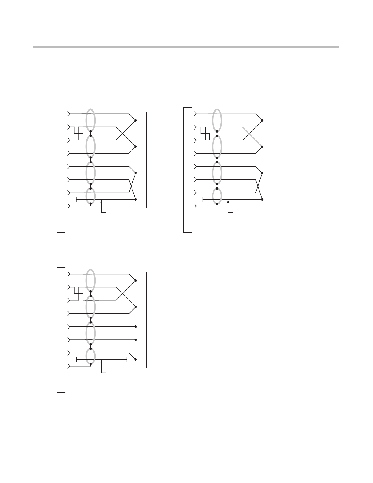
The I/O Wiring Data in Fig. 4 of this manual does not give the correct shield pairing of
cable wires, which is shown in the revised diagrams below and on the following page:
Daytronic 400 Series
Transducer Connections
Lebow 1600 Series
Rotary Transformer Torque
Transducer Connections
Daytronic 500 Series
Transducer Connections
(cont’d)
Correction
+SENSE
–EXC
–SENSE
+SIG –SIG
CAL
SENSE
1
A
2
B
3
C
4
9
.
.
.
A
SHIELD
+EXC
+SENSE
–EXC
–SENSE
+SIG –SIG
CAL
SENSE
1
A
2
B
3
C
4
9
.
.
.
A
SHIELD
Extra Wire, paired with CAL SENSE,
unconnected at Connector A
+EXC
+SENSE
–EXC
+SIG –SIG
CAL
SENSE
1
A
2
B
3
C
4
9
.
.
.
A
SHIELD
Extra Wire, paired with CAL SENSE,
unconnected at Connector A
–SENSE
+EXC
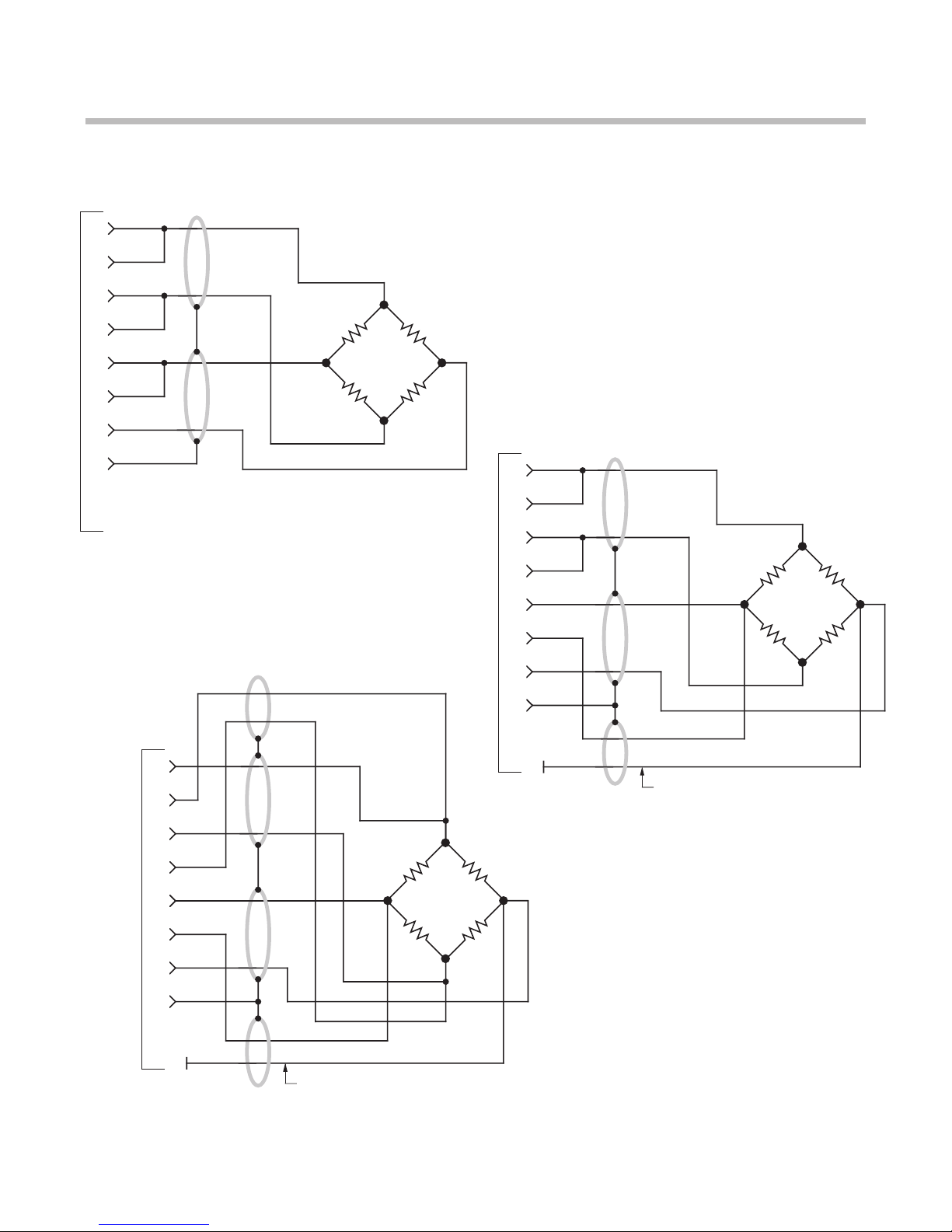
to Model 3178 Instruction Manual, v. SB.5.1 (cont’d)
Daytronic 3X78 Instrument to Generalized Strain Gage Transducer
Showing CAL SENSE Connection
4-Wire Configuration for Cables
Shorter Than 20 Feet
6-Wire Configuration for Cables
Shorter Than 20 Feet
8-Wire Configuration for Cables
Longer Than 20 Feet

Model 3178 Instruction Manual, v. SB.5.1
Pub. No. 3178M.5.1, Issued 03/01
MODEL
3178
STRAIN GAGE CONDITIONER
INSTRUCTION MANUAL
Part No. 91121
Daytronic Corporation
Dayton, OH • Tel (800) 668-4745
www.daytronic.com

This page intentionally blank.

Daytronic Corporation
TABLE OF CONTENTS
Section
Page
1
Description
.................................................
1
2
Installation and Cabling
......................................
3
3
Calibration
.................................................. 11
4
Block Diagram Description 14
5
Verification of Normal Operation
19
LIST OF ILLUSTRATIONS
Figure
Page
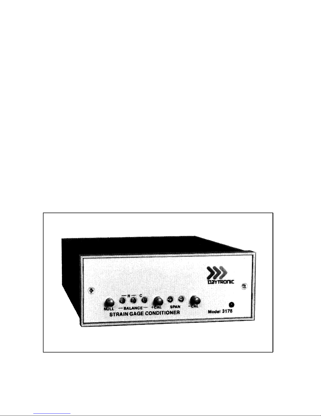
1 Model 3178 Strain Gage Conditioner
1
2
Instrument Mounting Dimensions
4
3
Instrument Panel Mounting
5
4 I/O Wiring
9
5
Front Panel Description
12
6
Block Diagram
..............................................
17
7
Star Bridge Construction
20
LIST OF TABLES
Table
Page
1
Specifications . . . . . . . . . . . . . . . . . . . . . . . . . . . . . . . . . . . . . . . . . . . . . . . .
2
PLEASE NOTE: Sections 6 and 7, Figures 8 and
9, and Table 2 have been
removed from this manual.
If you need information regarding specific 3178 components and circuitry,
please contact the Daytronic Service Department at (937) 293-2566.
...................................
.............................
.....................................
...........................
.............................
...................................
......................................
..................................................
Daytronic Corporation
INSTRUCTION MANUAL
MODEL 3178 STRAIN GAGE CONDITIONER
1. DESCRIPTION
The Model 3178 is a conditioner-amplifier for use with resistance strain gage
transducers in applications which require an ac excitation voltage. It supplies a 3.28
kHz
precision amplitude-regulated excitation, remotely sensed, to the transducer.
The instrument uses a phase-sensitive carrier amplifier-demodulator design so that
both direction and magnitude of the applied force are determined. The 3178 contains the necessary balancing and calibration controls and conditions/amplifies the
applied input to a standard Five-Volt Data Signal Level which is the output analog
signal level of 3000 Series Instruments. Two analog outputs, having low-pass cutoff
frequencies of 2 Hz and 400 Hz, are provided. The filtered outputs provide for
averaging or smoothing of signals containing noise or other unwanted dynamic
components which are periodic in nature. Filtering removes these dynamic compo-
nents so that stable digital indication and precise jitter-free
precise jitter-free
control action can be
obtained. The Model 3178 is shown in Figure 1 and the specifications are given in
Table 1.
Figure 1. Model 3178 Strain Gage Conditioner
1

Table 1. Specifications
Model 3178
Transducers:
4-arm bridges, 90
to
1000 ohms. nominally 0.5
mv/v to
5
mv/v,
full scale.
Cables:
4-, 5-,
or 7-wire, depending on application; 1000
feet
maximum length.
Bridge Excitation: Regulated 3.28
kHz
ac; nominally 2
vac.
Balance Adjustments:
10-turn
coarse and fine; will balance 1.5
mv/v
initial unbalance.
Span Adjustments:
10-turn
coarse and fine; 0.5 to 5
mv/volt,
full scale.
Analog Outputs: Two
analog
outputs
available; 0 to ±5 volts
with
50%
overrange, 5 milliamperes maximum.
Bandpass
is dc to 2 Hz or dc to
400 Hz.
Active
low-pass filters provide for
rolloff
of 60 dB per decade
above cutoff frequency. Full-scale slew time is
1.4/f
seconds, where f
is
the
cutoff frequency.
Output Ripple and Noise: 0.15% of full scale (rms) maximum for
400-Hz output;
0.02% of full scale (rms) on
2-Hz output.
Accuracy: 0.05% of full scale.
Dimensions: 1.7 x 4.41 x 8.5 (HWD inches).
Operating Temperature Range: 0
to +130 degrees F.
Power Requirements: 105 to 135 volts
ac,
50 to 400 Hz at 5
watts
maximum.
2
 Loading...