

DayTronic 3000 series, 3170 Instruction Manual

MODEL
3170
STRAIN GAGE CONDITIONER
SB.5.1
INSTRUCTION MANUAL
3000
Instrument Series

Copyright © 1996, Daytronic Corporation. All rights reserved.
No part of this document may be reprinted, reproduced, or used in any form or by
any electronic, mechanical, or other means, including photocopying and recording,
or in any information storage and retrieval system, without permission in writing
from Daytronic Corporation. All specifications are subject to change without notice.
Correction
1
A
2
B
3
4
C
9
A
D
B
C
+EXC
–EXC
+SENSE
–SENSE
+SIG
–SIG
CAL SENSE
.
.
.
A
Extra Wire, paired
with CAL SENSE,
unconnected at
Connector A
SHIELD
Bendix PT02E-10-6S
Burndy BT06AC-10-6S
1
A
2
B
3
4
C
9
D
A
B
C
+EXC
–EXC
+SENSE
–SENSE
+SIG
–SIG
CAL SENSE
.
.
.
A
Extra Wire, paired
with CAL SENSE,
unconnected at
Connector A
SHIELD
Amphenol 97-3106A14S-6S, AN3057-6
to Model 3170 Instruction Manual, v. SB.5.1
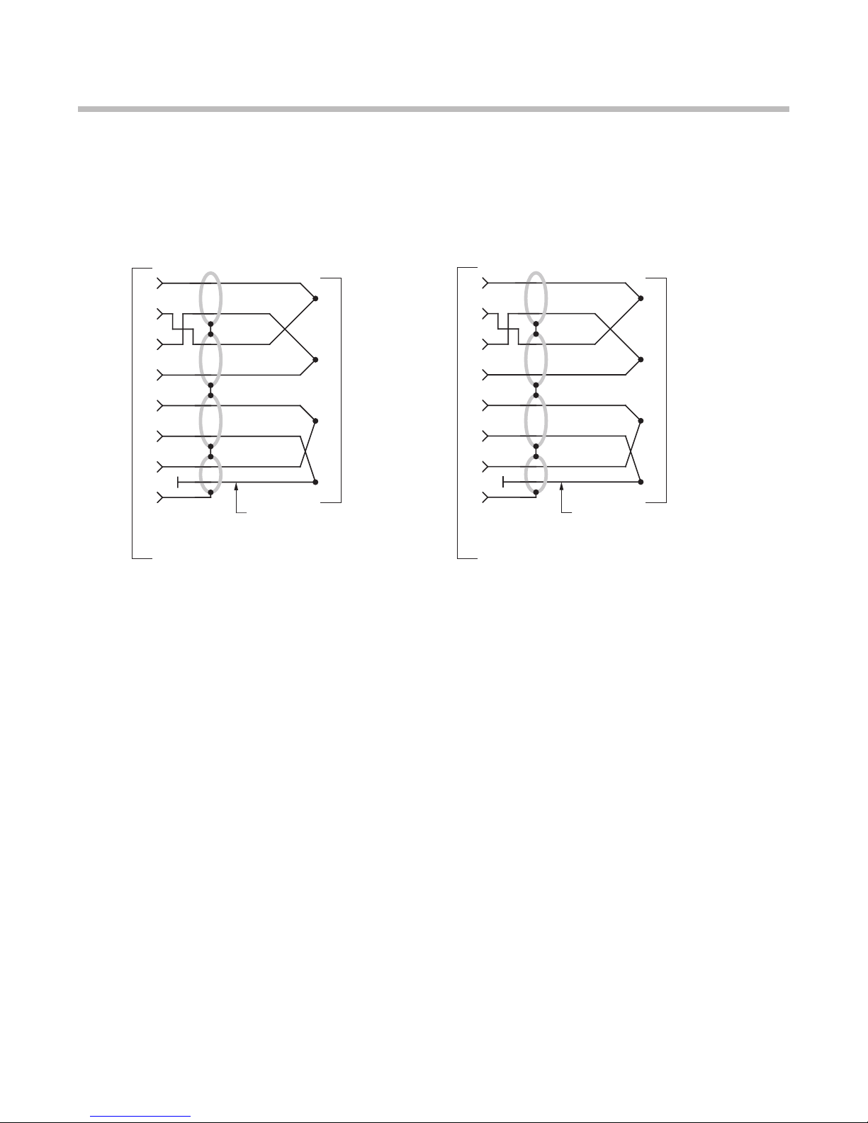
The I/O Wiring Data in Fig. 4 of this manual does not give the correct shield pairing of
cable wires, which is shown in the revised diagrams below and on the following page:
Daytronic 400 Series
Transducer Connections
Daytronic 500 Series
Transducer Connections
(cont’d)
Correction
+SENSE
–EXC
–SENSE
+SIG –SIG
CAL
SENSE
1
A
2
B
3
C
4
9
.
.
.
A
SHIELD
+EXC
+SENSE
–EXC
–SENSE
+SIG –SIG
CAL
SENSE
1
A
2
B
3
C
4
9
.
.
.
A
SHIELD
Extra Wire, paired with CAL SENSE,
unconnected at Connector A
+EXC
+SENSE
–EXC
+SIG –SIG
CAL
SENSE
1
A
2
B
3
C
4
9
.
.
.
A
SHIELD
Extra Wire, paired with CAL SENSE,
unconnected at Connector A
–SENSE
+EXC
to Model 3170 Instruction Manual, v. SB.5.1 (cont’d)
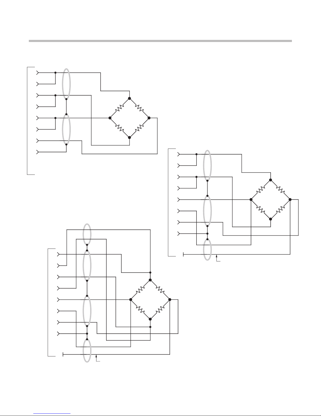
Daytronic 3X70 Instrument to Generalized Strain Gage Transducer
4-Wire Configuration for Cables
Shorter Than 20 Feet
6-Wire Configuration for Cables
Shorter Than 20 Feet
8-Wire Configuration for Cables
Longer Than 20 Feet

Model 3170 Instruction Manual, v. SB.5.1
Pub. No. 3170M.5.1, Issued 03/01
MODEL
3170
STRAIN GAGE CONDITIONER
INSTRUCTION MANUAL
Part No. 91132
Daytronic Corporation
Dayton, OH • Tel (800) 668-4745
www.daytronic.com

Daytronic Corporation
TABLE OF CONTENTS
Section
Page
1
Description
.................................................
1
2
Installation and Cabling ...................................... 3
3
Calibration .................................................. 8
4
Block Diagram Description
................................... 12
5
Verification of Normal Operation .............................. 14
LIST OF ILLUSTRATIONS
Figure
Page
1
Model 3170 Strain Gage Conditioner ...........................
1
2
Instrument Mounting Dimensions .............................
4
3
Instrument Panel Mounting .................................. 5
4
I/O Wiring Data
............................................
.
9
5
Front-Panel Description ...................................... 11
6
Block Diagram .............................................. 15
7
Star-Bridge Construction ..................................... 17
LIST OF TABLES
Table
Page
PLEASE NOTE:
Sections 6 and 7, Figures 8 and 9, and Table 2 have been
removed from this manual.
If you need information regarding specific 3170 components and circuitry,
please contact the Daytronic Service Department at (937) 293-2566.
1 Specifications ............................................... 2
Daytronic Corporation
INSTRUCTION MANUAL
MODEL 3170 STRAIN GAGE CONDITIONER
1. DESCRIPTION
The Model 3170 conditioner-amplifier module for use with resistance strain
gage transducers. It supplies a regulated dc excitation voltage to the transducer
bridge, provides the necessary balancing and calibration controls, and amplifies the
resulting signal to a standard Five-Volt Data Signal Level which is the output analog
signal level of 3000 Series Modules. The
3170
has three separate analog outputs,
each having a different bandpass: (1) dc to
2
kHz,
(2) dc to 200 Hz, and (3) dc to 2
Hz. Active low-pass filters are used to achieve the 200 Hz and 2 Hz cutoff
frequen-
cies.
The filtered outputs provide for averaging or smoothing signals containing
noise or other unwanted dynamic components which are periodic in nature. Filter-
ing removes these dynamic components so that stable digital indication and precise,
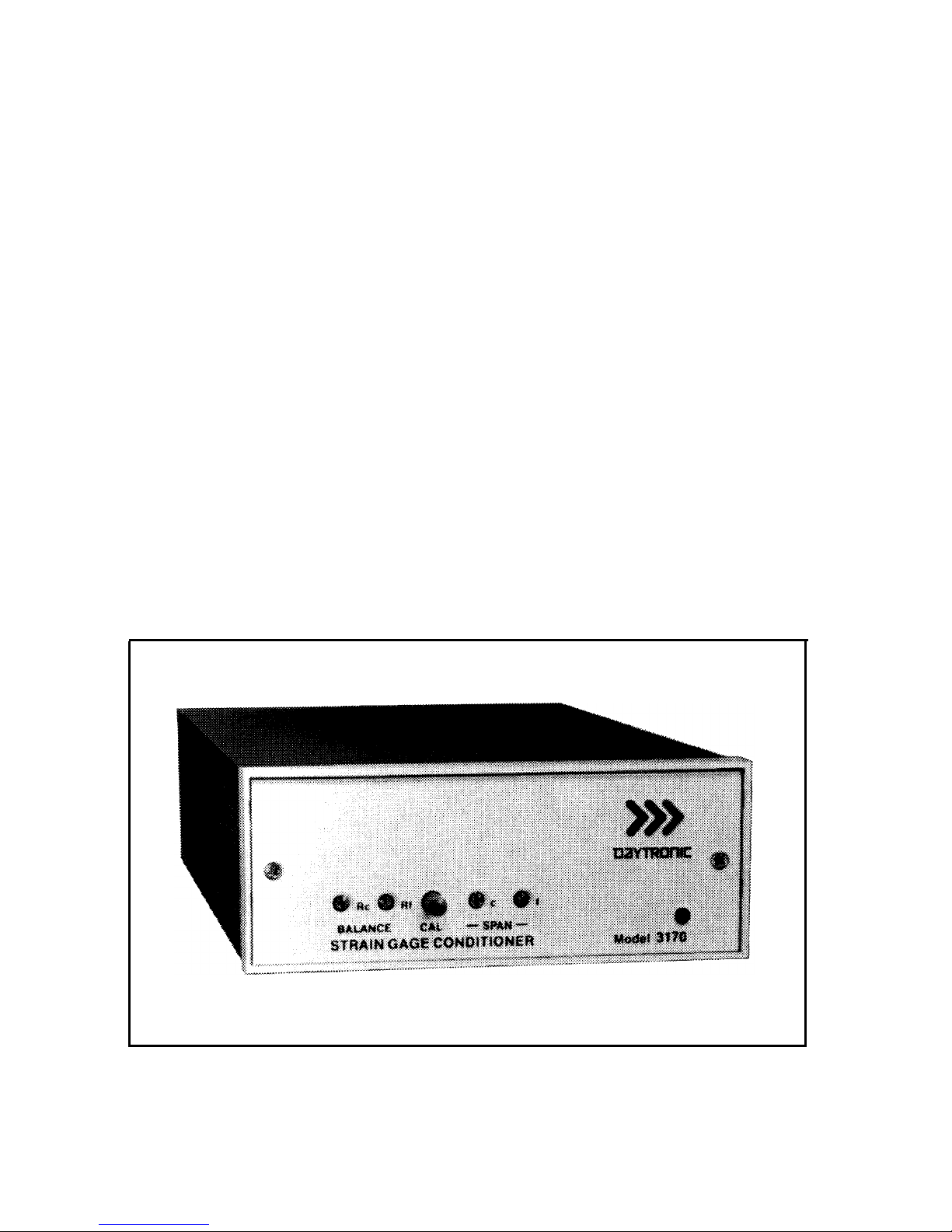
jitter-free control action can be obtained. The Model 3170 is shown in Figure 1 and
the specifications are given in Table 1.
Figure 1. Model 3170 Strain Gage Conditioner
1

Model 3170
Table 1. Specifications
Transducers: 4-arm bridges, 90
to
2000 ohms, nominally 1 to 8
mv/v, full
scale (120 ohms or less requires use of 5-volt excitation).
Cables:
4-, 5-,
or 7-wire, depending on application; 1000
feet
maximum length.
Bridge Excitation: Regulated 5 volts or 10 volts dc, selected
with
I/O
connector wiring. Transducers
with
sensitivity from 4 to 8
mv/v
full
scale must use
5-volt
excitation.
Balance Adjustments:
10-turn
coarse and fine; will balance 1.5
mv/v
initial unbalance.
Span Adjustments:
10-turn
coarse and fine; 1 to 8
mv/v,
full scale.
Analog Outputs: Three analog outputs available; 0 to ±5 volts with
50% overange, 5 milliamperes maximum.
Bandpass
is dc to 2 kHz, dc
to 200 Hz, or dc to 2 Hz, depending on
output
used. Active low-pass
filters provide for rolloff of 60
dB
per decade above cutoff frequency.
Full-scale slew
time
is 1 .4/f seconds, where f is
the
cutoff frequency.
Common Mode Rejection: Greater
than
80
dB.
Output Ripple and Noise: 0.15% of full scale (rms) maximum for
2-kHz and 100-Hz outputs; 0.02% of full scale (rms) on 2-Hz output.
Accuracy: 0.05% of full scale.
Dimensions: 1.7 x 4.41 x 8.5 (HWD inches).
Operating Temperature Range: 0 to + 130 degrees F.
Power Requirements: 105 to 135 volts ac, 50 to 400 Hz at 5 watts
maximum.
2
 Loading...