

Dayton Electronic LTC3201 User Manual
Te c h nology, Ltd.
R
User’s Manual
Model:LTC3201
1080i
Caution and Warning
CAUTION
RISK OF ELECTRIC SHOCK
DO NOT OPEN
Caution: To reduce the risk of electric shock, do not remove cover or back. No user-serviceable parts inside.
Refer servicing to qualified service personnel.
The lightning flash with arrowhead
symbol, within an equilateral triangle
is intended to alert the user to the
presence of uninsulated dangerous
voltage within the product enclosure
that may be of sufficient magnitude to
consitute a risk of electric shock.
WARNING: TO REDUCE THE RISK OF FIRE OR ELECTRIC SHOCK, DO NOT EXPOSE THIS APPLIANCE TO RAIN
OR MOISTURE.
CAUTION: CHANGES OR MODIFICATIONS NOT EXPRESSLY APPROVED BY THE PARTY RESPONSIBLE FOR
COMPLIANCE WITH THE FCC RULES COULD AVOID THE USERS AUTHORITY TO OPERATE THIS
EQUIPMENT.
The exclamation point within an
equilateral triangle is intended to
alert the user to the presence of
important operating and maintenance
(servicing) instructions in the literature
accompanying the TV.
FCC Caution
FCC Caution:
Any Changes or modifications not expressly approved by the party responsible for compliance could void the user's
authority to operate the equipment.
This device complies with part 15 of the FCC Rules. Operation is subject to the following two conditions: (1) This device
may not cause harmful interference, and (2) this device must accept any interference received, including interference that
may cause undesired operation.
Note: This equipment has been tested and found to
of the FCC Rules. These limits are designed to provide reasonable protection against harmful interference in a residential
installation. This equipment generates, uses and can radiate radio frequency energy and, if not installed and used in
accordance with the instructions, may cause harmful interference to radio communications. However, there is no guarantee that interference will not occur in a particular installation. If this equipment does cause harmful interference to radio or
television reception, which can be determined by turning the equipment off and on, the user is encouraged to try to
correct the interference by one or more of the following measures:
--Reorient or relocate the receiving antenna.
--Increase the separation between the equipment and receiver.
--Connect the equipment into an outlet
--Consult the dealer or an experienced radio/TV technician for help.
on a circuit different from that to which the receiver is connected.
comply with the limits for a Class B digital device, pursuant to part 15
1
Safety Precautions
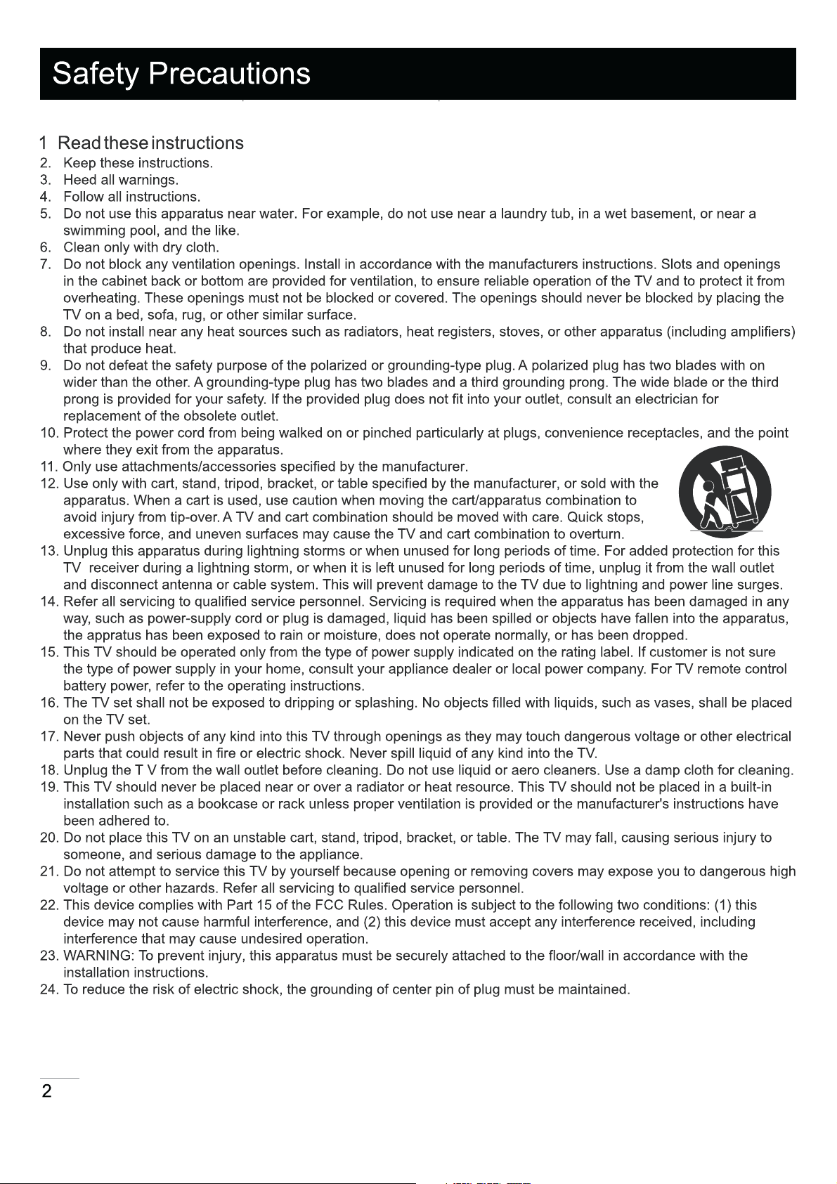
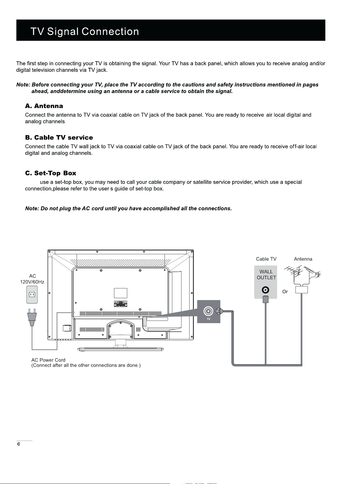
25. If an outside antenna or cable system is connected to the TV, be sure the antenna or cable system is grounded to
provide some protection against voltage surges and built-up static charges. Section 810 of the National Electrical
Code, ANSI/NFPA NO.70, provides information with respect to proper grounding of the mast and supporting structure,
grounding of the lead-in wire to an antenna discharge unit, size of grounding conductors, location of antenna
discharge unit, connection to grounding electrodes, and requirements for the grounding electrodes. (See Diagram
ANTENNA
LEAD IN
WIRE
GROUND CLAMP
ANTENNA
DISCHARGE UNIT
( NEC SECTION 810- 20)
GROUNDING CONDUCTORS
( NEC SECTION 810- 21)
GROUND CLAMPS
ELECTRIC SERVICE
EQUIPMENT
POWER SERVICE GROUNDING
ELECTRODE SYSTEM
( NEC ART 250, PART H)
Diagram Figure A
3
18
4

Audio Menu
Lock Menu
Time Menu
Channel Me nu
USB Menu
Wall Mounting Unit Specication
Product Specication
26
28
30
32
34
36
37
38
5
If you
Cable Connections
Choose Your Connections
TV LTC3200LED supports various of connecting ways from other devices (such as DVD, VCR, Set-top box, ect.). Please follow
the table sheet to choose the cables which adapt to your device. .
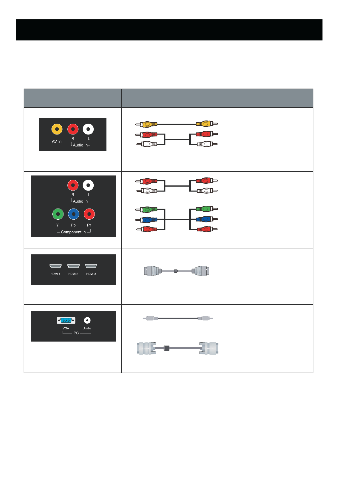
AV In, Audio In L and R
Component In, Audio Out L and R
HDMI-1, 2, 3
AV/Audio cable
Audio Cable
COMPONENT video cable
HDMI(TM) cable
Go to page 8
Cables
Go to page 9
Go to page 10
Audio cable with 3.5mm terminal
Go to page 11
VGA ,Audio
Note:HDMI,the HDMI logo, and High-Definition Multimedia Interface are trademarks or registered trademarks of
HDMI Licensing LLC
Caution:
Unplug the AC cord when you connect other devices to TV.
VGA cable
7
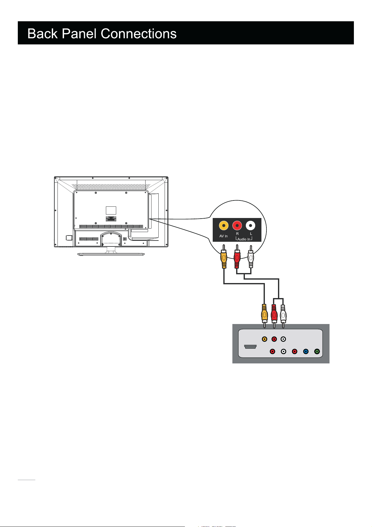
Connecting AV Composite device (Good Video Quality)
To connect an composite AV device, such as a DVD player, follow these steps:
1. Connect the Video-In jack on the back of TV to the video output jacks of device via video cable (yellow).
2. Connect the Audio-In L and R jacks on the back of TV to
Notice the left channel jack and plugs are white and the right channel jack and plugs are red.
Note: AV signal belongs to composite video. This kind of video signal has regular good display quality.
Composite Video Connection
The picture below is an example of a connection using the composite video jack.
the audio output jacks of device via audio cable.
The back of TV
Audio
Video
HDMI
LR
Audio
R
LPrPbY
The output panel of other device
8
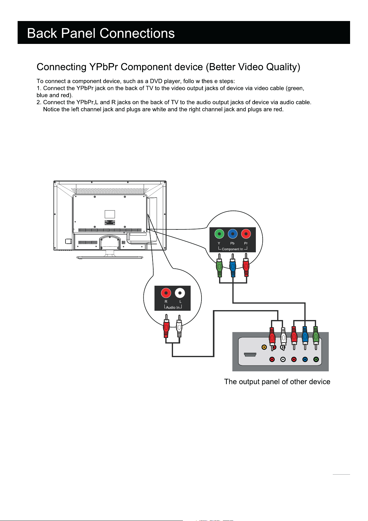
Note: Y/Pb/P r jacks are component video. This kind of video signal has better display quality.
Component Video Connection
The picture below is an example of a connection using the component video jack.
The back of TV
HDMI
Video
Audio
-3
Audio
RYPbPr
L
9
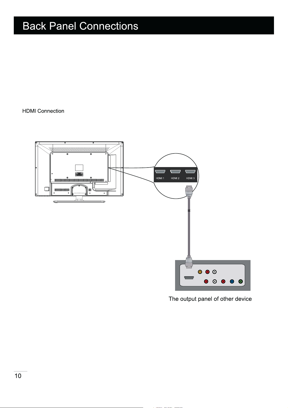
Connecting HDMI device (Best Video Quality)
To connect an HDMI device, such as a DVD player, Please Connect the HDMI-1,2or3 jack on the back of TV to the out
Put jacks of device via HDMI cable.
Note: HDMI(High-Definition Multimedia Interface) is a compact audio/video interface for transmitting uncompr
essed digital data. It carries the audio and video signal via the same cable and has the best display qual
ity.
The picture below is an example of a connection using the HDMI video jack.
HDMI
Video
Audio
Audio
LR
LRPbPr
L
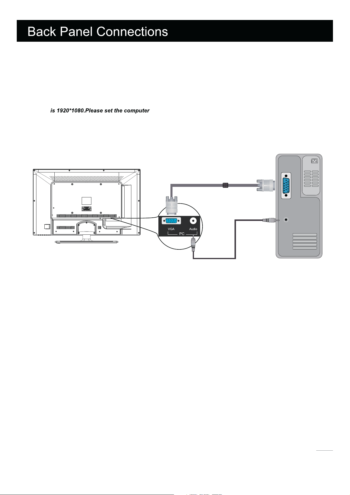
Connecting a computer
To connect a computer, follow these steps:
1. Connect the VGA port on the back of TV to the VGA output jack of device via D-sub 15-pin cable.
2. Connect the PC Audio In jack on the back of TV to the audio output jack of computer with audio cable (3.5mm).
Note: If you want
to use your TV as a monitor, please notice that the maximum resolution for GVC3200LED
PC Connection
The picture below is an example of a connection using your TV as a PC monitor.
PC
VGA
Speaker or
headphone
How to Obtain Various Kinds of Input Sources
After connection is done, press INPUT button on remote control or TV top panel to
choose the input source you need.See page 17, Basic Operation of TV.
11
 Loading...