

Page 1
Page 2
Note: Unit is set at the factory for 120V operation. Be sure to change the fuse
(2A rating) before switching to 230V operation.
(2)
Page 3

FCC Statement
1. This device complies with Part 15 of the FCC Rules.
Oper
ation is subject to the following two conditions:
(1) This device may not cause harmful interference, and
(2) This device must accept any interference received, including interference that
may cause undesired operation.
(3)
Page 4

Operating Guide: Dayton Audio
SPA250DSP Subwoofer Power Amplifiers
Table of Contents
Back panel and input/output (I/O) definition ............................................................................................................... 5
SPA250DSP wiring ........................................................................................................................................................ 6
Amp system block diagram ........................................................................................................................................... 7
DSP processing block diagram .................................................................................................................................... 7
Controlling your subwoofer via PC GUI ...................................................................................................................... 8
Volume/Phase ......................................................................................................................................................... 9
LPF and Subsonic ................................................................................................................................................ 10
5-Band PEQ .......................................................................................................................................................... 11
Limiter ..................................................................................................................................................................... 12
High Frequency Out ............................................................................................................................................. 13
Feature Menu display ............................................................................................................................................14-15
Firmware update guide ..........................................................................................................................................16-20
DSP Functions .............................................................................................................................................................. 21
Feature Controller (LCD matrix, single-knob) .................................................................................................. 21
Advanced Control (for GUI via USB port, PC) ................................................................................................. 21
Base Specifications (Audio Precision®) ................................................................................................................... 22
(4)
Page 5
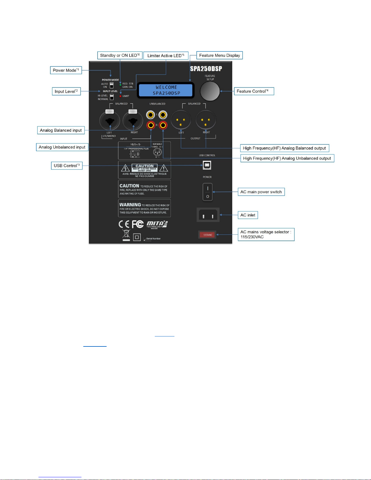
Back panel and input/output (I/O) definition
1. Power Mode: Select the either energy-saving or “always-on” power mode
o Au
to: Amp goes into standby after no detected signal input for 20 minutes*
o On: Amp is always on, regardless of input signal status.
* Amp will automatically turn on typically in one second or less once audio signals are resumed.
2. Analog input attenuation: Affects analog balanced and unbalanced inputs only.
o Normal: No attenuation.
o Hi: Attenuates input signal by -6dB.
3. USB Control: Used for PC-GUI communication with custom PC software included with your amp.
Please refer to PC-GUI user guide on Page 8. USB also allows for firmware update by Dayton Audio
release. See Page 16 for more on the system “flash” update process.
4. Feature Control: Single knob digital actuator with single/double-click enabled with rotary scrolling to
navigate the amp’s extensive feature menu.
5. Limiter LED: Lit when Limiter is active (Red).
6. Standby/On LED:
o Red when amp is in energy saving “stand by” state.
o Green when amp is operating normally.
(5)
Page 6
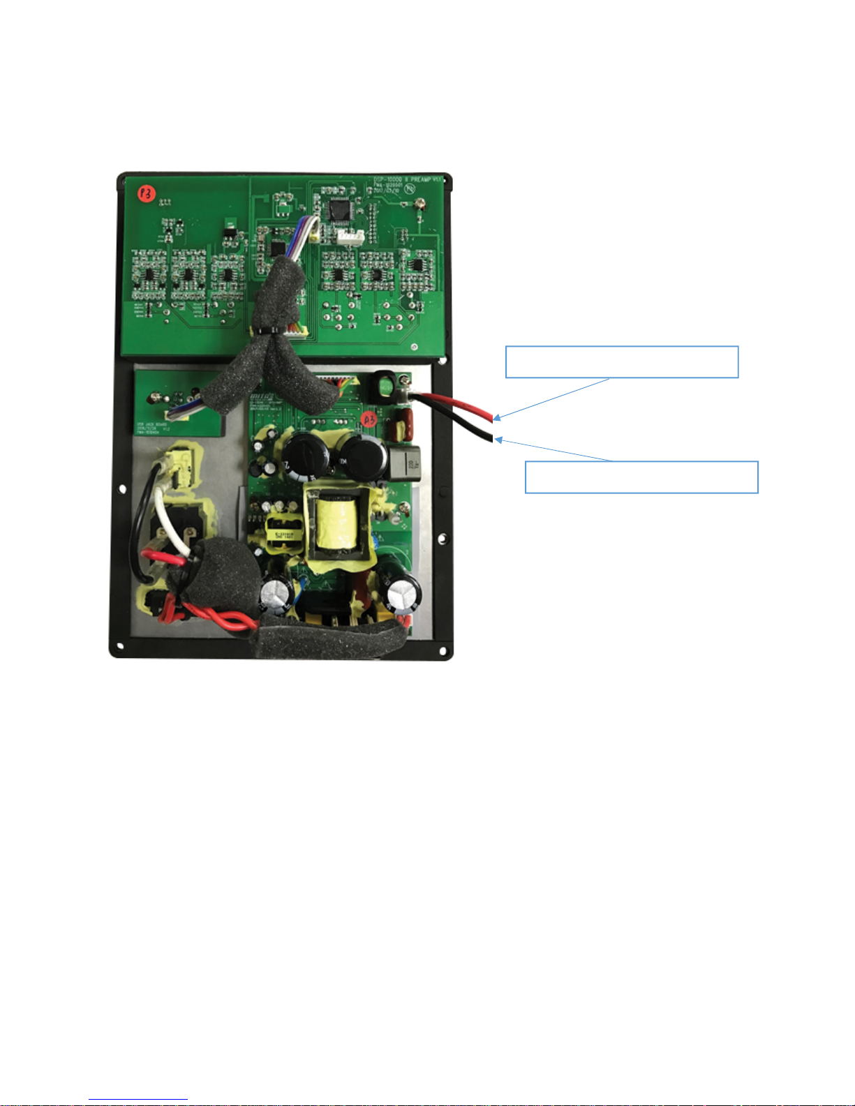
SPA250DSP wiring
Connect to speaker driver (+)
Connect to speaker driver (-)
(6)
Page 7

Amp system block diagram
DSP
processing block diagram
(7)
Page 8

Controlling your subwoofer via PC GUI
The PC GUI (literally “Personal Computer, Graphical User Interface”) is the primary mode to access
and adjus
if you require assistance.
t the DSP for subwoofer optimization. Follow all safe practices and contact Dayton Audio
Read Setting: Re
Save Settings to File: Save current settings to PC
Load Settings from File: Load previous saved setting to AMP
Reset to default setting: Reset the AMP to factory default
See next page: For a full depiction of the primary screens and detailed identification of each of your
amp GUI’s controls.
ad all the setting from amp
(8)
Page 9

Volume/Phase
• USB link indicator: W
LED indicator will light green. Otherwise, “LED” stays red.
• Processing Selection: Navigate across the DSP menu to adjust various DSP parameters.
• Sub in/out monitor: Monitor the input signal and sub output signal levels.
• Tools Drop Down Menu: Utilities for amp DSP management.
hen the communication via USB with amp is successful, the GUI’s
(9)
Page 10

LPF and Subsonic
Fil
ter ON/OFF Button: Enable or disable the selected filter.
Slope: Select roll-off gradient of the selected filter: -12dB/-24dB per octave.
Frequency (Hz): Adjust cut-off frequency of the selected filter.
(10)
Page 11

5-Band PEQ
PEQ
Detailed tool tips (shown a-d above):
Window: Graphical trace is NRT editable. Bands can be shaped by cursor or direct input and/or
sliders
5 Band-digital PEQ
a) Band On/Off: Bypass or enable by clicking the colorized 1~5 buttons
b) Center Frequency (CF): Adjust Center Frequency of each EQ band, 10~200Hz, steps: 1Hz.
c) Gain: Adjust the EQ gain (apparent volume), -12 ~ +6dB, steps: 0.1dB
d) Q (EQ width): Adjust the “Q” value, 0.4~16 , step: 0.1
(11)
Page 12

Limiter
Dual-
Band Limiter: Adjust, optimize, save, recall.
a) Threshold: Adjust the limiter threshold, 0~-12dB, step: 0.1dB
b) Attack: Adjust limiter’s “attack time”. This controls the time taken to attenuate signals over the
threshold to the specified threshold level. Range: 1/5/10/20/100ms
c) Release: Adjust limiter's “release time”. When signal is below threshold level, this controls the
time taken to restore back to original level. Range: 60/120/240/480/1000/2000ms
d) Frequency: The crossover frequency point between the 2 bands: Band 1 (Low Frequency) &
Band 2 (High Frequency).
(12)
Page 13

High Frequency Out
This block controls the DSP parameters for line level output only.
D
HPF Control:
elay: Adjust the time difference between High Frequency out and Subwoofer out.
Filter ON/OFF: Bypass or Enable the selected filter.
Slope: Select roll-off gradient of the selected filter: -12dB/-24dB per octave.
Frequency: Adjust cut-off frequency of the selected filter.
(13)
Page 14

Feature Menu display
Volume, Phase, Low-Pass
accessible via the included rotary control.
Volume (shown above) is selected by a single click, upon which
simple rotation allows 0.1dB adjustment. A “double-click” brings you
back to the main menu. Subsequent rotation of the controller from
the main menu navigates you through a series of setup menus.
Each of the “Function frames” at left correspond to the major feature
controls on the amp. Each feature control uses the same
single/double-click navigation. Note all detailed sub-features on the
next page. Scroll around your amp and get familiar with its simple
click and double-click feature rotation.
Filters, and all other controls are also
(14)
Page 15

MENU FRAME
WELCOME
FUNCTION FRAME
MENU
VOLUME
Single click
VOLUME
0 dB
Turn to adjust volume up/down
Single or double click to return to MENU FRAME
MENU
HIGH PASS
MENU
LOW PASS
MENU
PHASE DEGREE
MENU
HIGH PASS DELAY
MENU
SUBSONIC FILTER
Single click
Single click
Single click
Single click
Single click
HIGH PASS
ON/OFF
Single click
HIGH PASS
FREQ: 31.5 Hz
Single click
HIGH PASS
SLOPE: -12 dB
LOW PASS
ON/OFF
Single click
LOW PASS
FREQ: 31.5 Hz
Single click
LOW PASS
SLOPE: -12 dB
PHASE DEGREE
120°
HIGH PASS DELAY
7.5 ms
SUBSONIC FILTER
ON/OFF
Single click
SUBSONIC FILTER
FREQ: 25 Hz
Single click
SUBSONIC FILTER
SLOPE: -12 dB
Turn to Enable or Disable
Double click = MENU FRAME
Turn to select FREQUENCY
Double click = MENU FRAME
Turn to select SLOPE
Double click = MENU FRAME
Turn to Enable or Disable
Double click = MENU FRAME
Turn to select FREQUENCY
Double click = MENU FRAME
Turn to select SLOPE
Double click = MENU FRAME
Turn to adjust PHASE degree up/down
Single or double click to return to MENU FRAME
Turn to adjust HIGH PASS delay me up/down
Single or double click to return to MENU FRAME
Turn to enable or disable
Double click = MENU FRAME
Turn to select FREQUENCY
Double click = MENU FRAME
Turn to select SLOPE
Double click = MENU FRAME
MENU
PEQ
MENU
PRESET SAVE/LOAD
Single click Single clickSingle click
Single click
PEQ1
Double click
to return to
MENU FRAME
PEQ2
Turn
PRESET
SAVE LOAD
Turn to adjust select save or load
Double click to return to MENU FRAME
Single click
Double click
to return to
MENU FRAME
Single click
VOLUME
HIGH PASS
LOW PASS
PHASE DEGREE
PEQ1
FREQ: 63 Hz
Turn
PEQ1
GAIN: 0.0 dB
Turn
PEQ1
Q: 3.6
PEQ2
FREQ: 63 Hz
Turn
PEQ2
GAIN: 0.0 dB
urn
T
PEQ2
Q: 3.6
SELECT PRESET
P1 P2 P3
HIGH PASS DELAY
SUBSONIC FILTER
PEQ
PRESET SAVE/LOAD
PEQ1
FREQ: 63 Hz
Single click
Single click
Single click
Single click
Single click
Turn to select preset slot P1 P2 P3
Single click to save or load
PEQ1
LEVEL: 0.0 dB
PEQ1
Q: 3.6
PEQ2
FREQ: 63 Hz
PEQ2
GAIN: 0.0 dB
PEQ2
Q: 3.6
Turn to select FREQUENCY
Double click =
PEQ MENU FRAME
Turn to select GAIN
Double click =
PEQ MENU FRAME
Turn to select Q
Double click =
PEQ MENU FRAME
Turn to select FREQUENCY
Double click =
PEQ MENU FRAME
Turn to select GAIN
Double click =
PEQ MENU FRAME
Turn to select Q
Double click =
PEQ MENU FRAME
(15)
Page 16

DSP Functions
Feature Controller (LCD matrix, single-knob)
1. Volume Range: 0dB ~ -99dB.(0.1dB/step)
2. High pass Filter: (line level output only)
- Frequency Range: 30~125Hz (1Hz/step)
- Slope select: Disabled/-12dB/-24dB
3. High Pass Delay: 0~10msec(0.1msec/step)
4. Low pass Filter: (subwoofer amp output only)
- Frequency Range: 30~125Hz (1Hz/step)
- Slope select: Disabled/-12dB/-24dB
5. Variable Phase: 0° ~ 180°(1°/step)
6. Subsonic Filter: (subwoofer amp output only)
- Frequency Range: 25~40Hz (1Hz/step)
- Slope select: Disabled/-12dB/-24dB
7. P-EQ1/P-EQ2 adjustment: (subwoofer amp output only)
- Frequency Range: 30~125Hz (1Hz/step)
- Level Range: -12dB ~ +6dB (0.1dB/step)
- Q Factor Range: 0.6~14 (0.1/step)
8. Preset Save/Load: 3 Presets
Advanced Control (for GUI via USB port, PC)
1. I/O level meter (0 ~ -99dB)
2. 5-Band Parametric EQ Settings
- Frequency Range: 10~200Hz (1Hz/step)
- Level Range: -12dB ~ +6dB (0.1dB/step)
- Q Factor Range: 0.6~14 (0.1/step)
3. Limiter
- Threshold Range: -15dB ~ 0dB (0.1dB/step)
- Attack Time Range: 1/5/10/20/50/100ms
- Release Time Range: 60/120/240/480/1000/2000ms
(16)
Page 17

Base Specifications (Audio Precision®)
Input sensitivity
Output power
(4Ω)
Parameters Test conditions Typical value
RCA IN
XLR IN
Gain AMP output 100Hz @ 1W output +40.2dB
260W/4ohms
250W/4ohms
@115VAC
@115VAC
-10dBV
-10dBV
Input saturation level RCA left or right 100Hz
XLR left or right 100Hz
Noise Level volume=0dB (MAX)@A weighted -62.3dBV (S/N Ratio 97.9dB)
THD+N Ratio 20-20kHz Filter, Rated Power @100Hz < 1%
100Hz@115VAC, Input: -10dBV (L+R) 250 W
Auto ON/OFF
Auto ON sensitivity
Auto OFF time
Time delay
Power amplifier
Protection
Power Consumption: @230Vac/60Hz A- Standby mode
RCA Left ,100Hz
A- Short-circuit and under
load protection
B- Thermal protection
C-Power Supply Protection-Full Power
Protection
@230Vac/60Hz B- ON mode
@230Vac/60Hz C- Rated power
@115Vac/60Hz A- Standby mode
@115Vac/60Hz B- ON mode
@115Vac/60Hz C- Rated power
>2V(Hi-Level IN)
>2V(Hi-Level IN)
3mV
20mins
2ms
A-Yes
B-Yes
C-Yes
A- 0.50 W
B- 7.50 W
C- 311 W
A- 0.42 W
B- 7.50 W
C- 319 W
Weight: 1.1kG
Dimension: 262 (H) x 184 (W) x 60 (D) mm
SPA250DSP
(17)
Page 18

WARRANTY COVERAGE
Dayton Audio products are warranted to be free of all defects in material and workmanship for 5 YEARS from the date of purchase from
an authorized Dayton Audio dealer. This warranty and all rights provided are limited to the original owner and are non-transferable.
Dayton Audio's responsibility is limited to replacement or repair as set forth in this warranty statement.
Should a product require warranty service during this period, Dayton Audio will repair or replace without charge, any part or product
proving defective in material or workmanship. All warranty repairs and service must be performed by an authorized Dayton Audio
technician or service facility. The use of non-authorized repair services renders this warranty null and void, and any charges relating
to non-authorized repair are the responsibility of the product owner.
All expenses related to replacing or repairing a defective part or product under this warranty shall be assumed by Dayton Audio.
Dayton Audio reserves the right to replace defective product with a new or factory reconditioned unit.
WARRANTY EXCLUSIONS
1. This warranty does not cover product failure or damage resulting from misuse, abuse, neglect, accidents, alterations, standard
environmental deterioration, natural disasters, or improper use and/or installation.
2. This warranty does not cover cosmetic damage due to misuse or neglect. This includes paint damage, scratches, cracks or other
superficial marks related to improper use.
3. Failures arising from attempted servicing of a non-authorized Dayton Audio repair facility or technician are excluded from this warranty.
LIMITATION OF DAMAGES
In no event shall Dayton Audio be liable for consequential damages for breach of this warranty including installation charges, excessive
shipping expenses, property loss or other incidental loss. Some States do not allow the exclusion or limitation of incidental or
consequential damages, so the above limitation or exclusion may not apply to the buyer.
HOW TO OBTAIN WAR RA NTY SERVIC E
To obtain services under this warranty, the buyer shall contact Dayton Audio's authorized service provider, Parts Express, at
1-800-338-0531 x 780 to obtain a return authorization number (RA#).
The buyer must carefully pack the warranted product along with a copy of the original purchase receipt, the return authorization number
(RA#), and a description to the repair facility listed below. Shipping for warranty service is dependent upon the return policy where the
Dayton Audio product was purchased.
Parts Express
Attn: Dayton Audio Warranty Repairs RA# (please write your RA# here)
705 Pleasant Valley Drive
Springboro, Ohio 45066
NOTICE TO BUYER
This warranty gives you specific legal rights, and you may also have other rights which vary from state to state.
(18 )
Last Revised:
7/13/2017
 Loading...