

Page 1
4 x 8 DSP DIGITAL SIGNAL
PROCESSOR FOR HOME
AND CAR AUDIO
Model: DSP-408 User Manual
Page 2

Table of Contents
2. Table of Contents
3. Product Overview/General Safety Instructions/Box Contents
4. DSP Features and Technical Specications
5. Device Connections
6. Controlling the DSP
7. Connecting to Audio Sources and Mobile Devices
8. Operating the Windows Application
10. Operating the Mobile App
2
Page 3

Product Overview
The Dayton Audio DSP-408 is a feature-rich 4 input/8 output digital signal processor that was de-
signed to give you the tools to contour your audio system to t your tastes. The DSP-408 allows
the user to choose the application of their device. With two methods of powering the DSP, this
processor is the perfect addition to your home or car audio system. The DSP-408 can be controlled via a Windows PC, Android device, or an iOS device, unlike most mobile apps for DSPs,
the DSP-408 app offers the user full control over the DSP features.
Features:
● 4-channel high-level inputs with signal sensing turn-on
● 4-channel low-level RCA inputs
● Bluetooth 4.0 input for wireless connectivity and aptX audio streaming are available when
paired with the Dayton Audio DSP-BT4.0 (Purchased separately)
● 8-channel 3.5V RCA low-level outputs
● Real time signal processing control
● 80 bands of parametric EQ adjustment (10 bands per channel)
● DSP-RC multi-function wired remote allows for preset select and volume control (Purchased
separately)
● DSP-408 mobile tuning app for Android phones/tablets which features full control of the
DSP-408’s features
● Dimensions (WxHxD): 6.53" x 1.02" x 4.55" (165.9 x 25.91 x 115.6 mm)
Box Contents:
● 1 x DSP-408 processor
● 1 x Power adapter — Input: (100~240V, 50/60 Hz, 1A) Output: (12V, 1.5A)
● 1 x High-level input harness
● 1 x USB cable
● 2 x Mounting brackets
● 4 x Mounting screws
● 1 x Introduction card
Important Safety Instructions
To reduce the risk of electric shock, do not remove cover. No user serviceable
parts inside. Refer servicing to qualied personnel. To reduce the risk of re and
shock do not expose unit to rain or moisture. The unit should be connected to
an earth grounded AC electrical socket. The unit should be operated in a well
ventilated area. Minimum clearance is 2 inches from the ventilation openings.
3
Page 4

DSP Features and Technical Specications
Inputs Outputs
4 RCA preamp inputs 8 RCA preamp outputs
4 channel high-level inputs
1 USB A for PC control
1 USB B for DSP-BT4.0 connection
1 RJ11 for DSP-RC connection
1 12V DC power input jack
Bluetooth Functionality
● Real time DSP conguration over Bluetooth with the mobile app for Android and iOS devices
● Audio streaming from a Bluetooth device (utilizing aptX when supported)
USB Connection Functionality
● Real time DSP conguration using Windows PC software
● Audio playback via a Windows PC device
APP/Software Features
● 10 band parametric equalizer per channel
●
Variable crossovers: High/Low/Band-Pass slopes 6/12/18/24 dB, Linkwitz/Butterworth/Bessel/Riley
● Time delay: 0 to 277 cm or 8.1471 ms adjustable in 1 cm steps
● Input/Output mixing to customize signal path
● Preset les can be loaded, saved, recalled, or deleted
● Software controllable level attenuation on preamp and high-level inputs
● Customizable name/ID for each preset
DSP Features
● Analog Devices ADAU1701 SigmaDSP 28-/56 Bit Audio Processor
● Minimum/maximum voltage protection
● Reverse voltage protection
● Mute circuit and delay
Technical Specications
● High level input impedance: . . 180 ohms
● RCA input impedance: .......... ≥20K ohms
● Frequency response: ............20Hz-20KHz
● Output impedance: ................<50 ohms
● Maximum input level: ............≥3.2V
● Signal to noise ratio: ..............≥115dB.
● Remote out current: ..............>500mA
● Operating voltage: .................9-17V
4
Page 5
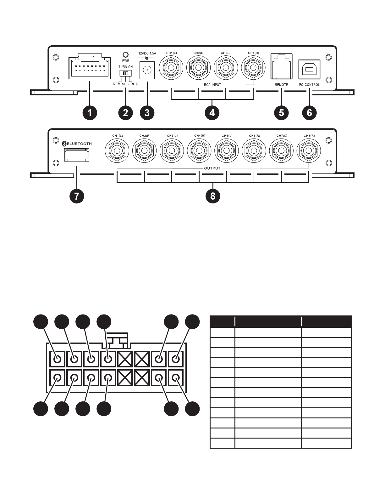
Device Connections
DSP-408 Callouts
1. 12V wiring harness 5. Remote input
2. Turn-on selector 6. PC control input (use with DSP-RC)
3. 12V DC jack input 7. Bluetooth dongle input (use with DSP-BT4.0)
4. RCA inputs 8. RCA outputs
12V Wiring Harness
1
2
Note: When using the DSP in the “SPK” mode
there may be a pop after turn off. Because of this,
we recommend the user installs a capacitor inline
with their tweeters to prevent any sort of damage.
3
4
5
6
7 9
8
10 12
11
PIN COLOR FUNCTION
1 WHITE CH 1 +
2 WHITE/BLACK CH 1 3 GR AY CH 2 +
4 GRAY/BLACK CH 2 5 GREEN CH 3 +
6 GREEN/BLACK CH 3 7 PURPLE CH 4 +
8 PURPLE/BLACK CH 4 -
9 RED REMOTE IN
10 BLUE REMOTE OUT
11 YELLOW 12V+
12 BLACK GROUND
5
Page 6

Controlling the DSP
Connecting via USB to a Windows PC
12VDC 1.5A
Windows Device
Connecting via Bluetooth to an Android Device
Bluetooth
or
Apple
iOS
6
Page 7

Connecting to Audio Sources
Analog Inputs:
RCA Inputs: The DSP-408 features 4 RCA inputs which can easily be connected to an after-
market car head unit, a receiver output in a home, or any audio device with RCA output. When
using the DSP in a car audio application where the source is an aftermarket head unit with
remote out, switch the turn-on selector to “REM” mode. When using the DSP in a home audio
application where an RCA source is being used, switch the turn-on selector to “RCA” mode.
High-level Inputs: The DSP-408 features 4 high-level inputs which are most commonly used
in car audio applications from a stock radio. When using the DSP for this application, switch the
turn-on selector switch to “SPK” mode.
Digital Input:
Bluetooth Input: Utilizing the DSP-BT4.0, you can connect your Android or iOS device to the
DSP-408 and stream audio content via aptX Bluetooth.
Installing the Software and Apps
The DSP-408’s mobile and desktop software and associated links can be found or downloaded
directly from the Dayton Audio website http://www.daytonaudio.com/dsp-408
Android: Download the Dayton Audio DSP Control app directly from the Google Play Store,
simply search Dayton Audio DSP Control in the search bar and choose the app developed by
Dayton Audio. This app will allow you to control the DSP via your mobile device and allow you to
stream audio content directly to the DSP when used with the optional Bluetooth dongle.
iOS: Download the Dayton Audio DSP Control app directly from the iTunes Store, simply search
Dayton Audio DSP Control in the search bar and choose the app developed by Dayton Audio.
This app will allow you to control the DSP via your mobile device and allow you to stream audio
content directly to the DSP when used with the optional Bluetooth dongle.
Windows: Download and install the DSP-408 software directly from Dayton Audio’s website.
7
Page 8

Operating the PC Application
1. Mixer: The user can select what percentage of each input is routed to each output simply by
using the sliders.
Master Volume: The user can control the volume of the system by moving the slider up or down
2.
3. Channel Level: The user can control the level of each channel by moving the slider up or down
4. Mute: The user can mute a channel by pressing the speaker button, to undo, press again.
5. Time Alignment:
a. Unit of Measure: At the bottom of the screen, you can select either “ms”, “cm”, or “in” as the
unit of measure. Note: Switching between unit of measurements will erase all values.
b. Controlling Delay: Click on the desired channel, then on the “Delay” box, and either enter
a number or use the up key to increase the delay, and the down key to decrease the delay.
Note: Only whole number increments can be entered so the shortest delay is 1 cm which
equals 0.294 ms or 0.394 in.
6. Phase Adjustment: The 0° button can be pressed to invert the phase 180°, to revert back,
press the 180° button.
7. Linking: The user can choose to link multiple channels together which allows for grouped
control over the EQ and crossovers. To create a link between channels, click the “Link” button
below each channel that you would like linked. To start a new set of linked channels, double
click the “Link” button for the channel you would like to start the new link with.
8
Page 9

Operating the PC Application Continued
1. High-pass/Low-pass lters:
a. Type: The user can select between 3 different crossover types; Linkwitz Riley, Bessel, and
Butterworth.
b. Frequency: The user can choose a crossover frequency 20-20,000 Hz.
c. Slope: The user can choose between 6/12/18/24 dB per octave slopes
2. Equalizer:
a. Center Frequency Selection: The user can change the center frequency that will be the
focus of the equalization by typing into the dialog box.
b. Q Selection: The user can change the Q by typing a number to the dialog box. The Q
adjusts the effective width of your equalization.
c. Level Adjustment: The user can move the EQ slider to adjust the amplitude of equalization.
d. Restore/Bypass EQ: The user can click the “Restore EQ” button to bypass the EQ for
the selected channel. To restore the EQ, simply click the same button again, which is now
labeled “Bypass EQ”.
e. Reset EQ: The user can clear the EQ for the selected channel, this action cannot be
undone, so be cautious when using this feature.
f. Shelf Filters: The user can choose to use shelf lters or PEQ on channels 1 and 10.
3. Graph: The graph at the top shows the overall response curve of all 10 PEQ lters.
4. Streaming Switch: Turn the streaming option on or off. When not streaming, the
recommended position for this switch is off (the left position).
Connection Status: This status display will inform the user if the PC is connected to a DSP-408.
5.
9
Page 10

Operating the Mobile App
There are 5 menu screens for the DSP-408’s mobile app (Dayton Audio DSP Control)
● The Main Menu
To return to the Main Menu, simply press the back button at the top left of any sub-menu.
1. Streaming Control: Turn the streaming option on or off. When not streaming, the
recommended position for this switch is off (the left position).
2. Volume Control: The main volume can be controlled via the slider or via the “+” sign to
increase and the “-” sign to decrease.
3. Preset Selection: Select a saved preset by touching one of the 6 preset buttons.
4. Access to Other Menus: Touch the “Advanced settings” button.
10
Page 11

● Advanced Settings - Set Delay Menu
Each channel 1-8 features its own delay control.
1. Controlling Delay: Select either “ms”, “cm”, or “in”, then use the “+” sign to increase the
delay, and the “-” sign to decrease the delay. Alternatively, you can use the slider to increase
or decrease the delay as needed.
the shortest delay is 1 cm which equals 0.294 ms or 0.394 in. Also, s
measurements will erase all values.
Note: Only whole number increments can be entered so
witching between unit of
11
Page 12

● Advanced Settings - The Equalizer Menu
Each channel 1-8 features its own independent 10-band parametric EQ.
Parametric EQ provides parametric lters, each of which can be set for a peaking lter. The
graph at the top shows the overall response curve of all 10 PEQ lters.
1. EQ Band Selection: The user can touch the small, white-outlined box below the level control
of the desired EQ band. To reveal the remaining EQ bands, gently swipe left on the level
adjustment sliders.
2. Center Frequency Selection: The user can move the slider to choose the center frequency
that will be the focus of your equalization.
3. Q Selection: The user can move the slider to adjust the effective width of your equalization.
4. Level Adjustment: The user can move the slider for each EQ band to adjust the level of
equalization.
5. Restore/Bypass EQ: The user can touch the “Restore EQ” button to temporarily bypass the
EQ for the selected channel. To restore the EQ, simply touch the same button, which is now
labeled “Bypass EQ”.
6. Reset EQ: The user can clear the EQ for the selected channel, this action cannot be undone,
so be cautious when using this feature.
12
Page 13

● Advanced Settings - The Output Menu
Each channel 1-8 features an output menu that allows the user to select a desired crossover,
output level, and phase of that channel.
1. Phase Control: The “0°” button can be pressed to invert the phase 180°, to revert back,
press the same button again, which is now labeled “180°”.
2. Muting: The user can mute a channel by pressing the button, to undo, press again.
Level Control: The user can increase the level of a channel by pressing the “+” sign or decrease
3.
the level by pressing the “-” sign. Alternatively, the user can also use the slider to adjust level.
4. Crossover Type: The user can select between 3 different crossover types; Linkwitz Riley,
Bessel, and Butterworth. Note: To disable the crossover, change the slope to 6dB/Oct and
move the frequency to the limit (20 Hz for HP, 20,000 Hz for LP).
5.
Crossover Frequency: The user can choose a crossover frequency between 20 and 20,000 Hz.
6. Crossover Slope: The user can choose between 6/12/18/24 dB per octave slopes
7. Saving: The user can save the tune they are working on to any of the 6 presets by clicking
the “Save” button and then selecting a preset number and hitting save. Additionally, the user
can delete or recall tunes in this menu as well.
8. Linking: The user can choose to group multiple channels together which allows for grouped
control over the EQ and Output menus. To create a group, click the “Link” button, then the
channels to be grouped, and then press the “Grouping” button. To add channels, click the
“Group” you would like to add to and then the designated channel, then click the “Join” button.
Groupings can also be deleted by selecting the “Group” and pressing “Delete” button.
13
Page 14

● Advanced Settings - Mixer Menu
Each channel 1-8 features a mixing control
1. Input/output Conguration: The user can select what percentage of each input is routed to
each output simply by using the sliders.
14
Page 15

5-Year Limited Warranty
See daytonaudio.com for details
Dayton Audio® Last Revised: 7/12/2018
daytonaudio.com
tel + 937.743.8248
info@daytonaudio.com
705 Pleasant Valley Dr.
Springboro, OH 45066
USA
 Loading...