

Page 1
CLASS D STEREO
AMPLIFIER 60 WPC
Model: APA102 User Manual
Page 2
CAUTION
RISK OF ELECTRICAL SHOCK
DO NOT OPEN
CAUTION: TO REDUCE THE RISK OF ELECTRIC SHOCK, DO NOT REMOVE THE COVER. NO
USER SERVICABLE PARTS INSIDE. REFER SERVICING TO QUALIFIED PERSONNEL!
The exclamation point within an equilateral triangle is intended to alert the user of the presence of important
operating and maintenance (servicing) instructions in the literature accompanying the appliance.
FO NOIT A NALPXE
SAFETY SYMBOLS
to constitute a risk of electric shock to persons.
• T :GNINRA W O T NEVERP FIRE OR SHOCK HAZ T ON OD ,DRA EXPOSE THIS AP M RO NIAR O T ECNAILP OISTURE. UT A RA P PA EHT S T ON L LAHS
• WARNING: TO PREVENT FIRE OF SHOCK HAZARD, DO NOT USE THIS PLUG WITH AN EXTENSION CORD, RECEPTACLE OR OTHER OUTLET
• NINRA W G: THE MAINS PLUG IS USED AS D T CENNOCSID EVICE. D T CENNOCSID EHT EVICE . ELBALIA VA Y L IDAER NIAMER L LAHS
• NINRA
W G: A T T A ESU Y L NO CHMENTS OR ACCESSORIES SPECIFIED OR PROV . RERUTCA F UNAM EHT Y B DEDI
BE EXPOS RD O T DE IPPING OR SPLASHING T A HT DNA OBJECTS FILLED WITH LIQUIDS, SUC V SA H ASES, T ON L LAHS BE DECALP
. SUT A RA P PA NO
UNLESS THE BLADES CAN BE T DET R ESNI Y L LUF O DALB T NEVERP E EXPO . ERUS
gninthgil ehT flash eht ot resu eht trela ot dednetni si elgnairt laretaliuqe na nihtiw lobmys daehwo r ra eht htiw
fo eb yam taht e r usolcne ’stcudo r p eht nihtiw ”egatlov suo r egnad“ detalusninu fo ecnese r p sufficient magnitude
SNOITCURTSNI YTEFAS TNA T ROPMI
1. Read these instructions.
2. Keep these instructions.
3. Heed all warnings.
4. Follow all instructions.
5. Do not use this product near water.
6. Clean only with dry cloth.
7. Do not block any ventilation openings. The ventilation should not be
impeded by covering the ventilation openings with items such as
newspaper, tablecloths, curtains, etc. Install in accordance with the
manufacturer's instructions.
8. Do not install near heat sources such as radiators, heat registers, stoves,
or other apparatus (including amplifiers) that produce heat. No open
flame sources, such as lighted candles, should be placed on the product.
9. Do not bypass the safety purpose of the polarized or grounding type plug.
A polarized plug has two blades with one wider than the other. A
grounding type plug has two blades and a third grounding prong. The
wide blade or third prong is provided for your safety. If the provided plug
does not fit into your outlet, consult an electrician for replacement of the
obsolete outlet.
10. Protect the power cord from being walked on or pinched particularly at
the point of exit from the product.
11. Only use attachments/accessories specified by the
manufacturer.
12. Use only with the cart, stand, tripod, bracket, or table
specified by the manufacturer, or sold with the
product. When a cart or rack is used, use caution
when moving the cart/product combination
to avoid injury from tip-over.
13. Unplug the product during lightning storms or when
unused for long periods of time.
14. Refer all servicing to qualified personnel. Servicing is required when the
product has been damaged in any way, such as power supply cord or
plug is damaged, liquid has been spilled or objects have fallen into the
product has been exposed to rain or moisture, does not operate
normally, or has been dropped.
15. WARNING: To reduce the risk of fire or electric shock, do not expose this
product to rain or moisture. The product shall not be exposed to dripping
or splashing and that objects filled with liquids, such as vases, shall not
be placed on product.
16. WARNING: The mains plug/appliance coupler is used as disconnect
device, the disconnect device shall remain readily operable.
17. This equipment is a Class II or double insulated electrical appliance.
It is designed in such a way that it does not require a ground
connection to electrical earth.
18.
This lightning flash with arrowhead symbol within an equilateral triangle
is intended to alert the user to the presence of non-insulated “dangerous
voltage” within the product’s enclosure that may be of sufficient magnitude to constitute a risk of electric shock.
Warning: to reduce the risk of electric shock, do not remove cover (or
back) as there are no user-serviceable parts inside. Refer servicing to
qualified personnel.
The exclamation point within an equilateral triangle is intended to alert
the user to the presence of important operating and maintenance
instructions in the literature accompanying the appliance.
MAGNETIC FIELD: !!CAUTION!! Do not locate sensitive high-gain equipment such as preamplifiers or tape decks directly above or below the unit. Because
this amplifier has a high power density, it has a strong magnetic field, which can induce hum into unshielded devices that are located nearby. The field is
strongest just above and below the unit. If an equipment rack is used, we recommend locating the amplifier(s) in the bottom of the rack and the preamplifier
or other sensitive equipment at the top.
2
Page 3
Thank you for purchasing the Dayton Audio APA102 Class D Stereo Amplifier. This amplifier features bridged outputs that
can provide continuous 160W power into an 8 ohm load. Class D amplifiers offer the audio fidelity of a Class AB amplifier
while providing greater power efficiency.
FEATURES:
• Class D Amplification
• MAIN / INTERRUPT priority input switching
• MAIN auxiliary output
• Speaker A/B switching
• Front panel Balance and Volume controls
• Signal sensing “Power On” and Trigger mode
• Rear mounted treble and bass controls
• Short circuit and thermal protection
SPECIFICATIONS
Power Output: 2 x 60W per channel with <1% THD+N 8-ohm load
2 x 75W per channel with <1% THD+N 4-ohm load
1 x 160W @ 1 kHz with <1% THD+N 8-ohm load (minimum)
Frequency Response: 10 – 30,000 Hz
Signal to Noise Ratio: 100dB
Channel Separation: 65dB
Input Sensitivity: 700mV
Bass/Treble Control: +/-12dB @ 100 Hz and 10 kHz
AC Power Consumption: 200W maximum
Dimensions: 2.15" H x 16.9" W x 7.65" D
Weight: 4.7lbs
16.9" (430mm)
2.15"
(55mm)
7.65"
(194mm)
3
Page 4

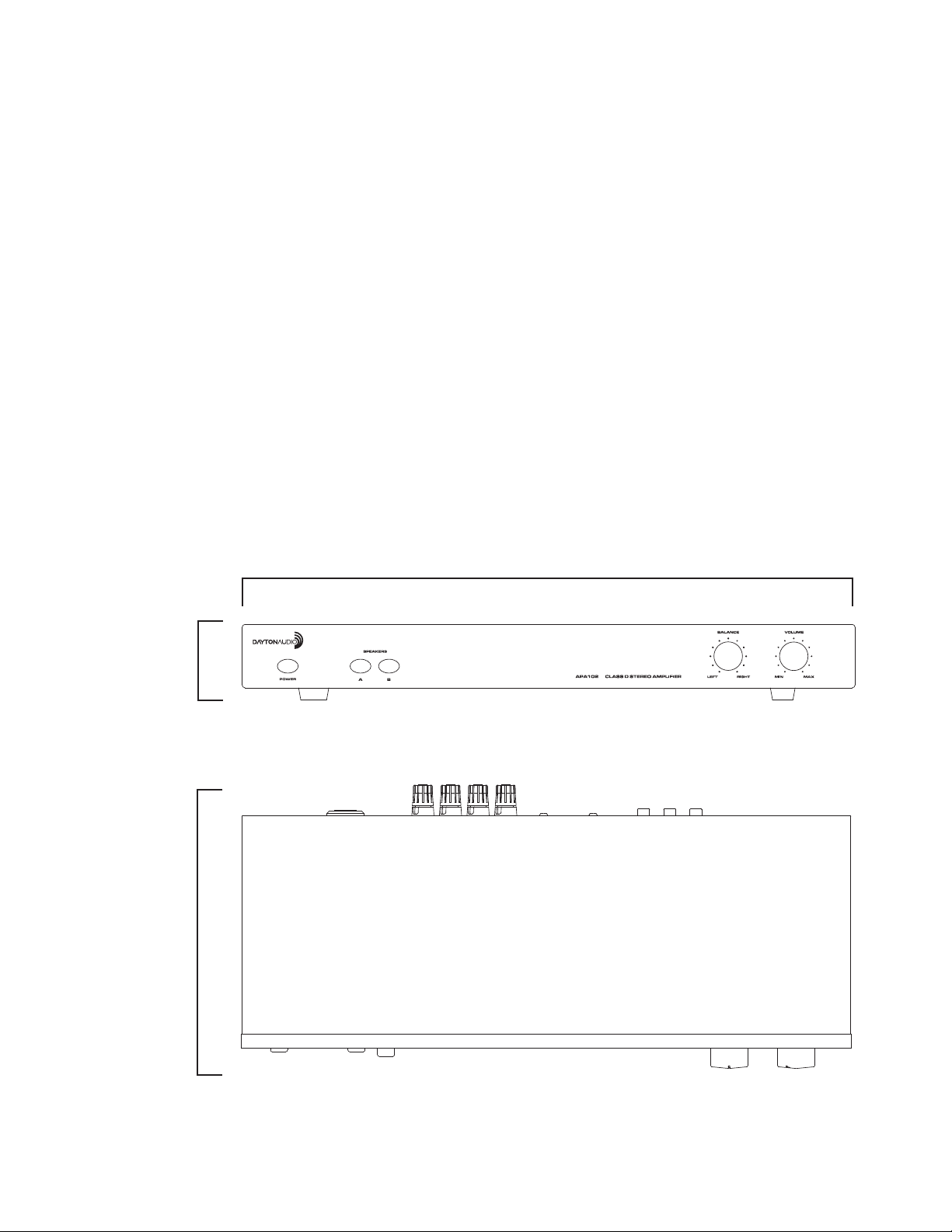
3 2 1
4
FRONT PANEL CONTROLS
1. Power Switch
Switches the APA102 on or off. A red LED indicates connection to AC power
while in standby mode. Turns green indicating audio signal is present.
2. Speaker Selector
Selects speaker zone A or B. For A + B zones push both buttons in.
7
5
Connect
Receiver
Here
8
REAR PANEL CONTROLS
5. Bass and Treble Controls
These controls can adjust bass and treble frequencies +/- 12dB at 100Hz
and 10kHz.
6. Interupting Line Input
This is the secondary input, use MAIN IN for your main input.
INTERRUPTING INPUT can be used if a second source is desired and
takes over when signal is present and has at least a 5mV level. When
there is no signal, or a signal with less than 5mV level, the amp switches
back to MAIN IN after a brief delay.
7. Main Input/Output
MAIN IN should be used as the “primary” or main input for the amplifier.
Connect your receiver or main source to this input. Use MAIN OUT to
pass MAIN IN signal to another amplifier.
8. 12V Trigger In/Out
Allows the APA102 to be powered on by other electronics or to power on
other electronics via a 3.5mm mini phone plug cable.
9. Mode Select Switch
Switches the amplifier from Stereo mode to Bridged mode.
STEREO MODE
If you will be connecting one or two pair of speakers to the amplifier,
place the switch in the “Stereo” position. NOTE: For playing 2 pairs of
speakers (A plus B), make sure each speaker has an impedance of 8
ohms or greater.
BRIDGED MODE
When set to “Bridged” mode, the amplifier is a single channel mono
amplifier.
BRIDGED MODE- MONO APPLICATION
For bridged mode, playing Right and Left together as mono output, plug
RCA cables in to Right and Left RCA at MAIN input. Set the MODE
switch to BRIDGED and follow the instructions for bridged speaker
connection in the SPEAKER TERMINALS section of this manual.
NOTE:
The APA102 supplies 160W in bridged mode, Please verify that your
speakers are capable of handling such power to avoid possible damage!
10. AUTO ON Select Switch
Power can be turned on and off manually via the switch on the front
panel or automatically by signal sensing. Set it to NORMAL for manual
power on/off. Set to AUTO for signal sensing; the amp will turn on when
audio signal is detected at the inputs.
NOTE: The front panel rpower switch must be in the ON position
(pushed in) for the AUTO ON feature to operate.
11. Speaker Zone a Output
Speaker output terminals for zone A. Minimum impedance: 8 ohm
bridged or 4 ohm stereo.
10
8
lenaP tno r F .1 e r ugiF
3. Balance
Fades speaker output between the Right and Left Channels
4. Volume
Adjusts amplifier volume.
11 6 9
12 13
14
lenaP raeR .2 e r ugiF
12. Speaker Zone B Output
Speaker output terminals for zone B. Minimum impedance: 8 ohm
bridged or 4 ohm stereo.
SPEAKER TERMINALS - STEREO MODE
For stereo output connect the speaker’s positive (red) terminal to the
amplifier’s positive (red) terminal, and the speaker’s negative (black)
terminal to the amplifier’s negative (black) terminal for each Right and
Left speaker.
SPEAKER TERMINALS - BRIDGED MODE
Place the “MODE” switch in the “BRIDGED” position and use both red
terminals to connect to the speaker. Connect the speaker’s positive (red)
terminal to the amplifier’s red (+) terminal noted next to the bridging
mark, and the speaker’s negative (black) terminal to the amplifier’s
unmarked positive (red) terminal.
NOTE:
NOTE: Use Class 2 wiring for speaker connections.
To wire the output connector: 1. Strip the insulation off each speaker wire
Warning:
NOTE: To prevent sonic degradation in your speaker installation, total
80' or Less – 16 Gauge 2-Cond. CL3/FT4 Rated
80' to 150' – 14 Gauge 2-Cond. CL3/FT4 Rated
150' or more – 12 Gauge 2-Cond. CL3/FT4 rated
13. Unswitched Outlet 120VAC
14. Power Cord
This amplifier is configured for operation at 115V (North America). A fuse
Only one zone (A or B) can be bridged. Do not attempt to bridge
both A and B speaker terminals! This may result in a lower impedance than
the amplifier is designed for and may damage your amplifier. The minimum
impedance for the total load connected in bridged mode is 8 ohms.
to expose 3/8" (10 mm) of bare conductor. 2. Unscrew the output
terminal binding post several twists, insert each wire into the correct
terminal. 3. Tighten binding post by twisting clock-wise until it is firmly
clamping the speaker wire.
While the amplifier does self-protect under most improper
output conditions, misconfiguration of loudspeaker mode and incorrect
connection of loudspeakers could damage connected loudspeakers and/or
amplifier. Please refer installation to a qualified installation professional,
and always check state and local electrical codes when installing.
speaker wire resistance should be kept below 0.5 ohms. This table lists
recommended speaker wire gauge versus wire run length.
The APA102 has an un-switched electrical outlet on the rear panel for use
with low power auxiliary devices; up to 400 watts. This outlet provides
power as long as the APA102 is plugged in, even if the unit is not turned on.
located internally protection from fault conditions. Refer to qualified
service personel should this need to be replaced.
4
Page 5

APPLICATIONS
STEREO SETUP
In this configuration, the mode switch is set to “Stereo”. Connect the line out
jacks from a stereo pre-amplifier or source to the MAIN input jacks of your
APA102. Next connect your speakers to the terminals marked “Speaker A”
observing proper polarity. Select the “A” speakers using the front panel zone
selection buttons. Connect a second (optional) pair of speakers to the
terminals marked “Speaker B”. If you are connecting 4 speakers to the
APA102 they must be 8 ohm speakers only. Press A and B together to use
both zones.
L
R
SETUP FOR MULTIPLE SOURCE
In the multiple source set up, a distributed audio system is connected to the
APA102 as a local zone amplifier via the MAIN inputs. Normally the distributed audio system will be the audio source for the APA102 . The distributed
audio is then passed on to be used by additional zones or sub zones in the
distributed system via the MAIN outputs.
Note: Main Out only duplicates what source is connected to the Main Input,
ideal for adding additional Amplifier or connect to Power Subwoofer.
L
R
(From Pre-amp or Receiver Line Out)
WARRANTY COVERAGE
Dayton Audio products are warranted to be free of all defects in material and workmanship for 5 YEARS from the date of purchase from
an authorized Dayton Audio dealer. This warranty and all rights provided are limited to the original owner and are non-transfer able.
Dayton Audio's responsibility is limited to replacement or repair as set forth in this warranty statement.
Should a product require warranty service during this period, Dayton Audio will repair or replace without charge, any part or product
proving defective in material or workmanship. All warranty repairs and service must be performed by an authorized Dayton Audio
technician or service facility. The use of non-authorized repair services renders this warranty null and void, and any charges
relating to non-authorized repair are the responsibility of the product owner.
All expenses related to replacing or repairing a defective part or product under this warranty shall be assumed by Dayton Audio.
Dayton Audio reserves the right to replace defective product with a new or factory reconditioned unit.
WARRANTY EXCLUSIONS
1. This warranty does not cover product failure or damage resulting from misuse, abuse, neglect, accidents, alterations, standard
environmental deterioration, natural disasters, or improper use and/or installation.
2. This warranty does not cover cosmetic damage due to misuse or neglect. This includes paint damage, scratches, cracks or other
superficial marks related to improper use.
3. Failures arising from attempted servicing of a non-authorized Dayton Audio repair facility or technician are excluded from this warranty.
LIMITATION OF DAMAGES
In no event shall Dayton Audio be liable for consequential damages for breach of this warranty including installation charges, excessive
shipping expenses, property loss or other incidental loss. Some States do not allow the exclusion or limitation of incidental or
consequential damages, so the above limitation or exclusion may not apply to the buyer.
HOW TO OB TAIN WAR RA NTY S ERVIC E
To obtain services under this warranty, the buyer shall contact Dayton Audio's authorized service provider, Parts Express, at
1-800-338-0531 x 780 to obtain a return authorization number (RA#).
The buyer must carefully pack the warranted product along with a copy of the original purchase receipt, the return authorization number
(RA#), and a description to the repair facility listed below. Shipping for warranty service is the responsibility of the buyer.
Parts Express
Attn: Dayton Audio Warranty Repairs RA# (please write your RA# here)
705 Pleasant Valley Drive
Springboro, Ohio 45066
NOTIC E TO BUY ER
This warranty gives you specific legal rights, and you may also have other rights which vary from state to state.
(From Local Source Line Out)
(From Pre-amp Line Out) (Out to Additional Zones)
The audio output of a local source, such as an MP3 Player, CD, television,
computer, etc., is connected to the APA102 via the INTERRUPTIN G inputs,
and whenever the local source is active its signal will take priority over the
distributed audio signal present at MAIN input . However, the distributed
audio signal will still be present at the MAIN input. In this circumstance the
audio output of the local source will be heard via the APA102. Once the local
source is turned off or muted, the APA102 will automatically switch back to
the distributed audio system as an audio source, assuming the local source
remains inactive. There is a delay of up to 6 seconds when switching from
INTERRUPTING input back to MAIN inputs.
daytonaudio.com
tel + 937.743.8248
info@daytonaudio.com
Dayton Audio® Last Revised: 8/9/2016
5
705 Pleasant Valley Dr.
Springboro, OH 45066
USA
 Loading...