

Page 1
500W SUBWOOFER
PLATE AMPLIFIER
Model: SPA500 User Manual
Page 2
Thank you for purchasing the Dayton Audio® SPA500 subwoofer amplifier, one of the most versatile and powerful subwoofer amplifiers available. The SPA500 has the power to drive even the most power-hungry subwoofer systems.
FEATURES:
• Patented tracking downconverter power supply for
high efficiency
• Class AB output stage for clean, controlled output
• Low frequency parametric EQ allows you to boost or
cut to custom-tailor the sound
• Advanced soft clip circuitry improves headroom and
protects woofers
• Variable low pass filter
• Switchable 115/230V input voltage
INSTALLATION:
The SPA500 is designed to provide high fidelity subwoofer amplification and is tailored for home audio, home theater, and
studio environments.
It is not recommended for use in DJ, pro-sound, or other high-duty-cycle applications. The amplifier runs cool thanks to its
high efficiency, but care should be taken to leave some room for air circulation above and behind the amplifier.
(2)
Page 3

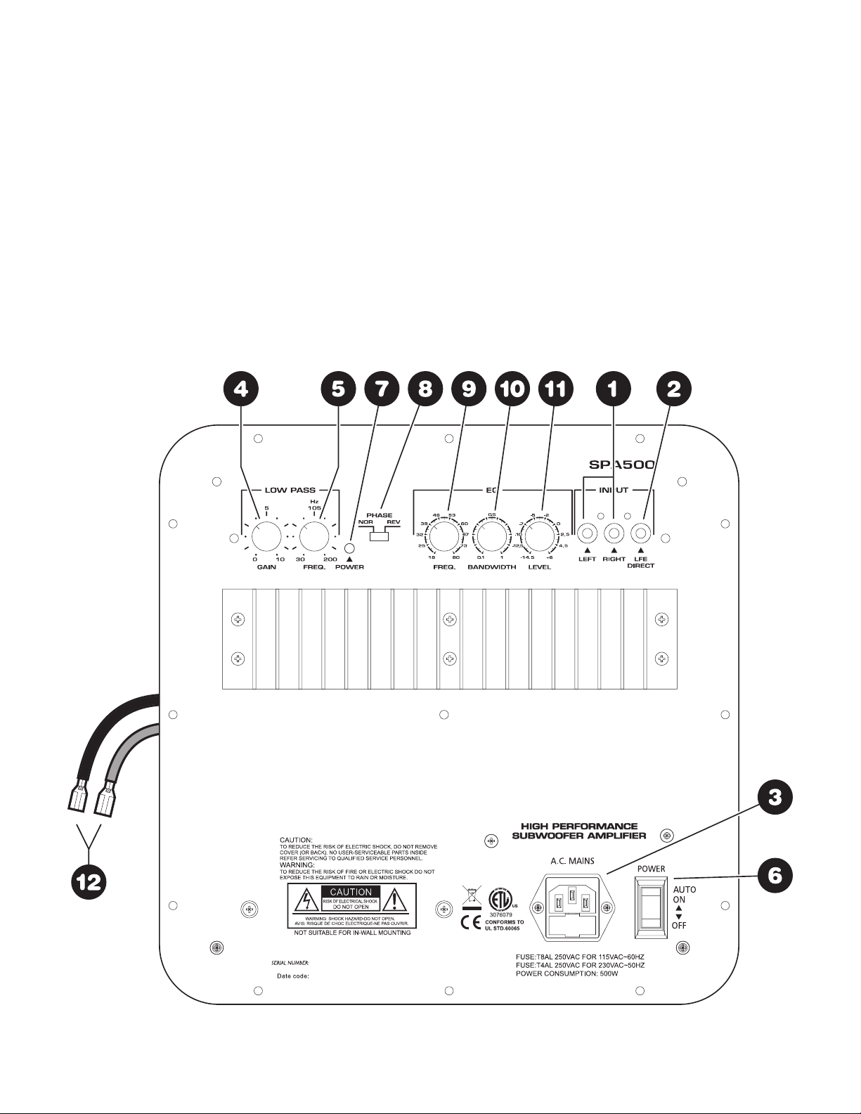
INPUT CONNECTIONS
1.) Left/Right inputs
RCA style jacks that will accept standard line level inputs
from a pre-amp level source. They will accept a stereo signal
and internally combine it into mono. Both left and right input
jacks must be connected to the source in order to drive the
amplifier to full output. The use of a “Y” cord is suggested if a
mono source is all that is available.
2.) LFE direct input
RCA jack that will accept a signal from the mono LFE (Low
Frequency Effects) output on a pre-amp or receiver that is
equipped with a dedicated sub bass output. This input bypasses the amplifier’s own internal low pass filter circuitry,
relying instead on the processed output provided by the source
equipment. This would be the recommended connection for
most home theater surround sound receivers and pre-amps.
We would also suggest the use of the LFE input when an
external line level electronic crossover or frequency dividing
network is used.
3.) Power input
This unit features an IEC grounding type power input connector. The IEC inlet connector also features an integrated fuse
holder that contains the AC line fuse. For 230V input, remove
the fuse holder, rotate 180 degrees, and re-install. In most
230V applications a separate power cord will be required
and is not included.
CONTROLS/INDICATORS
4.) Low Pass, Gain
Will match the amplifier’s input sensitivity to the output of the
pre-amp source. If the source output has a variable control,
we recommend that the user spend a moment or two determining the best balance between the two controls. When a
balance is found between low noise, linear level control, and
sufficient level to drive the amp to the required output, the
gain knob can be considered to be the “volume control” for
the subwoofer system.
5.) Low Pass, Frequency
This control is used to establish the highest frequency that
the subwoofer will reproduce and has a range between 30
and 200 Hz. If your main speakers have good bass capability, you could set the control to a fairly low value at 40, 60,
or even 100 Hz. If the main speakers are smaller or do not
have much bass output, set the control higher. Experiment
with the amount of “overlap” that you will experience when all
speakers are playing in the same range. This can be helpful
when integrating the subwoofer with the rest of the system
and with the room.
6.) Power Switch
This switch manually turns the unit on and off. When switched
to the on position, the unit will first turn on and be fully operational. After a period of 10-15 minutes without a signal the unit
will go into “stand by” mode.
7.) Power LED
When the power switch is moved to the “on” position, the
LED will illuminate in green, and the amp will be in “stand
by” mode. If a low level signal of about 3 millivolts or greater
is applied to the input, the light will change color to yellow to
indicate that the amplifier is fully operational and receiving
typical music program. As input signal increases to the onset
of clipping the LED will turn red, which indicates that the clip
limiting circuitry is activated. If an input signal is not detected
for 10 to 15 minutes, the amp will go back to “stand by” mode
and the LED will change back to green.
8.) Phase
This two-position (NOR = 0° phase and REV = 180° phase)
switch helps to compensate for differences in the acoustical
and electrical characteristics between the subwoofer and the
main system speakers. The relative locations of speakers in
the system can cause significant disturbances in speaker
interaction due to time delay issues, or the destructive phase
interferences that can occur at certain frequencies. The use
of this switch in conjunction with altering the location of the
subwoofer can have a dramatic effect on system integration.
The “NOR” setting would be considered the normal or default
setting, but be sure to experiment during system set-up.
PARAMETRIC EQUALIZER
The SPA500 features a fully parametric equalizer to help you
to achieve the best possible subwoofer performance. Professional sound engineers have for many years considered the
parametric EQ to be one of the most accurate, versatile, and
high fidelity tools for audio enhancement. A greater degree of
control can be achieved when using the EQ’s unique ability
to vary the frequency to be affected, the amount of boost or
cut, and the width or narrowness at the selected frequency.
9.) EQ-Frequency
Establishes the specific frequency at which EQ boost or cut
may be applied between 18 Hz and 80 Hz.
10.) EQ-Bandwidth
Determines how narrow or wide the EQ curve will be within a
range of 0.1 to 1.0. If for example a frequency of 60 Hz were
selected along with a Q of 0.1, the frequencies to either side
of 60 Hz would be less affected. This is a narrow bandwidth
that could be useful for “surgically” removing an offending peak
without disturbing adjacent frequencies. At the other extreme,
a Q of 1 would result in a much broader effect which could
be used for smooth overall bass boost or cut, to balance the
overall tone character of the sub.
11.) EQ-Level
Permits the application of up to 6 dB of boost or 14.5 dB of cut
at the selected frequency and bandwidth. Setting the control
at the 0 position effectively removes the EQ from the circuit
path. It is good to remember that high levels of boost reduce
amplifier headroom; it is the same as turning up the low pass
gain control but only at the selected EQ frequencies. It would
be helpful to reduce or increase the low pass gain control to
balance the amount of cut or boost applied by the EQ.
12.) Output Lead for Subwoofer Driver:
This rear mounted output lead connects the amplifier to the
subwoofer driver. The output lead is roughly 20" long and
is color coded. The red wire uses an insulated .250" quick
disconnect and the black wire uses an insulated .205" quick
disconnect. These connectors can be easily removed if your
driver requires another size or type of connector. Be sure to
observe proper polarity when connecting the amplifier to your
subwoofer driver (red = positive, black = negative).
(3)
Page 4

NOTES ABOUT HUM:
While the SPA500 has been designed to minimize the possibility of hum in the subwoofer system, it is still possible that a hum
will occur in rare circumstances. Its safety grounding can create a path for small amounts of 60 Hz energy to travel trough
the line-level audio system. While not dangerous, this energy can cause diffi culty with the subwoofer auto signal sensing
circuit, and at the very least will interfere with the quiet enjoyment of your system. The fi rst course of action should be trying to
make sure that all of the audio components are connected to either the same electrical outlet, or at least into the same circuit
branch. Next, cable TV systems are notoriously the culprit, so be sure to try disconnecting all coaxial feeds that are connected
to the system. If this solves the problem, install a coaxial line isolator and reconnect the system. In the very worst case, a linelevel audio isolator/transformer connected to the line-in of the subwoofer amplifi er will usually solve the problem.
SPECIFICATIONS:
Rated Power Output: (0.92 % THD) 273 watts* into 8 ohms, 540 watts* into 4 ohms
*Based on one-third power duty cycle
Signal to Noise Ratio: 98 dB A-weighted
Effi ciency: 75%
Input Impedance: 12K ohms
Low Pass Adjustment: 30 Hz – 200 Hz
Phase Adjustment: 0° (NOR) or 180° (REV)
Parametric EQ:
Frequency: 18 Hz – 80 Hz
Bandwidth: 0.1 – 1 Q
Level: -14.5dB – +6dB
Dimensions: 11-15/16" W x 11-15/16" H x 5-1/4" D
Enclosure Cutout: 10" x 10"
Power Requirements: 115/230 VAC, 50 Hz/60 Hz
Stand-by Power Rating: 115V 24W; 230V 18.4W
Weight: 15.2 lbs.
IMPORTANT SAFETY INSTRUCTIONS
To reduce the risk of electric shock, do not remove cover. No user serviceable parts inside. Refer servicing to qualifi ed personnel.
To reduce the risk of fi re and shock do not expose unit to rain or moisture. The unit should be connected to an earth grounded AC
electrical socket. The unit should be operated in a well ventilated area. Minimum clearance is 2 inches from the ventilation openings.
Note: Unit is set at the factory for 115V operation. Be sure to change the fuse (5A rating) before switching to 230V operation.
Dayton Audio products are warranted free from defects in material and workmanship for 5 years from date of purchase. 1 year warranty applies to the
following products: powered subwoofers and electronic devices (e.g. subwoofer amplifi ers, and plate amplifi ers, as well as the Omnimic V2 and DATS
loudspeaker testing devices). In the rare case of a product failure, please contact your place of purchase or call our Customer Support Department at
(937) 743-8248.
There are no other warranties, either expressed or implied, that extend the foregoing, and there are no warranties of merchantability or fi tness for any
particular purpose. Dayton Audio is not responsible for any consequential or inconsequential damage to any other unit or component or the cost for
installation or extraction of any component of the audio system, or for the improper use of products. This includes but is not limited to burnt voice coils,
overheating, bent frames, holes in the cone, or broken lead wires.
This warranty gives you specifi c legal rights and you may also have other rights that vary from state to state.
Non-Warranty Service: If non-warranty service is required, the product may be sent to the Company for repair/replacement, transportation prepaid, by
calling (937) 743-8248 for details, complete instructions, and service fee charges.
Warranty Information
Warranty Limitations
daytonaudio.com
tel + 937.743.8248
info@daytonaudio.com
Dayton Audio® Last Revised: 4/29/2015
(4)
705 Pleasant Valley Dr.
Springboro, OH 45066
USA
 Loading...