

Page 1
A
Klippel Non-Linear Test
Results
LSI (Large Signal
Identification)
Driver Name: ND90-4
Introduction
Large Signal Modeling
t higher amplitudes, loudspeakers produce substantial distortion in the output signal, generated by
nonlinear ties inherent in the transducer. The dominant nonlinear distortions are predictable and are
closely related with the general principle, particular design, material properties and assembling
techniques of the loudspeaker. The Klippel Distortion Analyzer combines nonlinear measurement
techniques with computer simulation to explain the generation of the nonlinear distortions, to identify
their physical causes and to give suggestion for constructional improvements. Better insight into the
nonlinear mechanisms makes it possible to further optimize the transducer in respect with sound
quality, weight, size and cost.
Nonlinear Characteristics
The dominant nonlinearities are modelled by variable parameters such as
Bl(x) instantaneous electro-dynamic coupling factor (force factor of the
motor) defined by the integral of the magnetic flux density B over
voice coil length l as a function of displacement
KMS(x) mechanical stiffness of driver suspension a function of
displacement
LE(i) voice coil inductance as a function of input current (describes
nonlinear permeability of the iron path)
LE(x) voice coil inductance as a function of displacement
More information about these parameters can be found in the article “
Displacement limits”
Nonlinear Parameters
Page 2
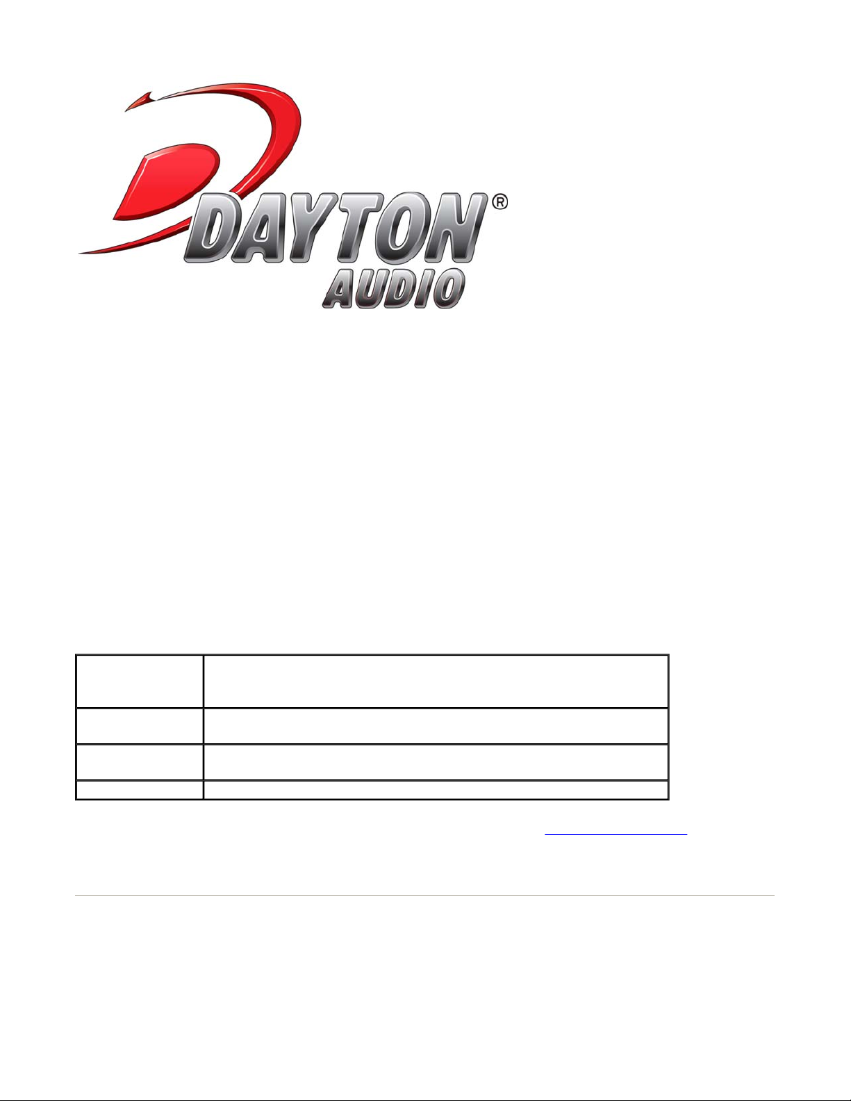
The electrodynamic coupling factor, also called Bl-product or force factor Bl(x), is defined by the
integral of the magnetic flux density B over voice coil length l, and translates current into force. In
traditional modeling this parameter is assumed to be constant. The force factor Bl(0) at the rest
position corresponds with the Bl-product used in linear modeling. The red curve displays Bl over the
entire displacement range covered during the measurement. You see the typical decay of Bl when the
voice coil moves out of the gap.At the end of the measurement, the black curve shows the confidential
range (interval where the voice coil displacement in this range occurred 99% of the measurement
time). During the measurement, the black curve shows the current working range. The dashed curve
displays Bl(x) mirrored at the rest position of the voice coil – this way, asymmetries can be quickly
identified. Since a laser was connected during the measurement, a "coil in / coil out" marker is
displayed on the bottom left / bottom right.
More information regarding Bl(x) and its optimization can be found in the article “
Rest Position”
Optimal Voice Coil
Page 3
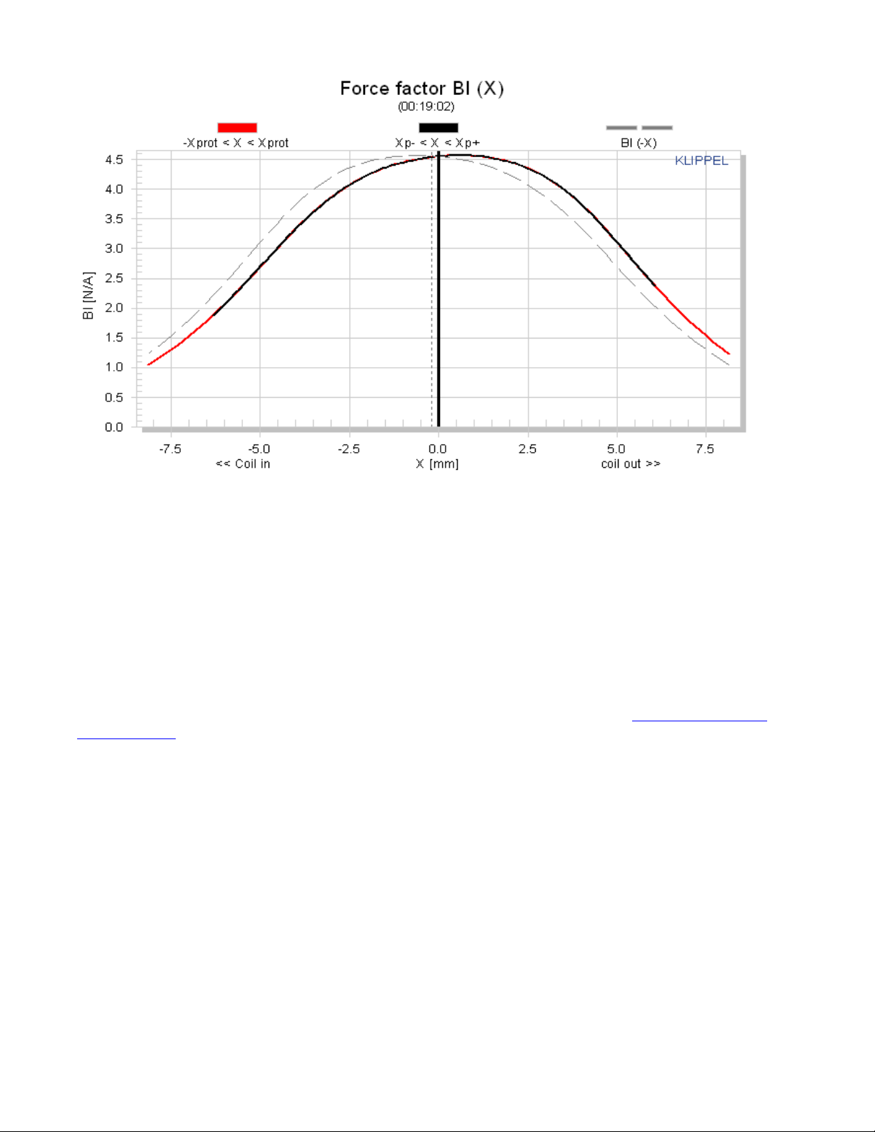
The stiffness KMS(x) describes the mechanical properties of the suspension. It's inverse is the
compliance CMS(x)
More information regarding Kms(x) and its optimization can be found in the article “
Mechanical Suspension”
Adjusting
Page 4
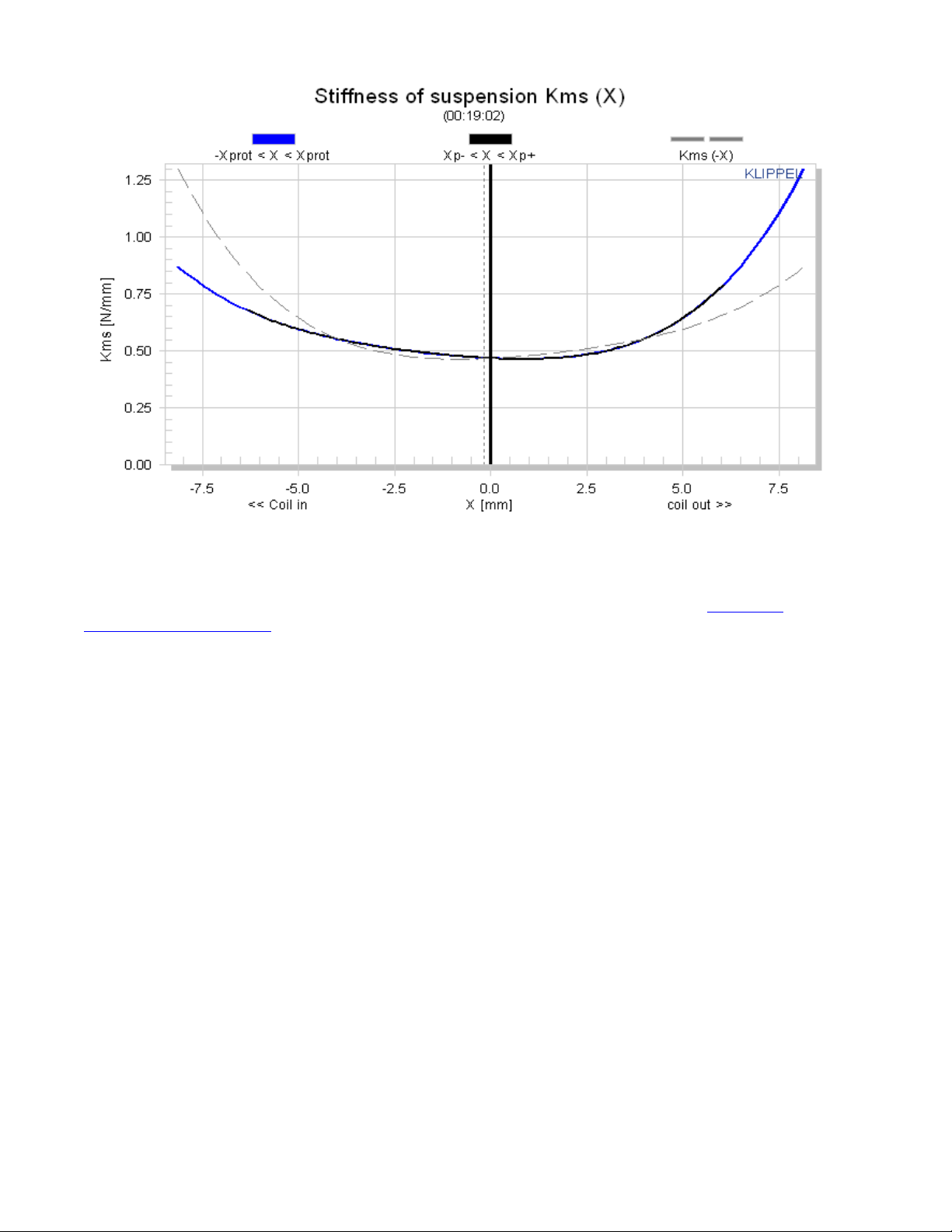
The inductance components Le (x) and Bl(i) of most drivers have a strong asymmetric characteristic. If
the voice coil moves towards the back plate the inductance usually increases since the magnetic field
generated by the current in the voice coil has a lower magnetic resistance due to the shorter air path.
The nonlinear inductance Le(x) has two nonlinear effects. First the variation of the electrical impedance
Page 5

with voice coil displacement x affects the input current of the driver. Here the nonlinear source of
distortion is the multiplication of displacement and current. The second effect is the generation of a
reluctance force which may be interpreted as an electromagnetic motor force proportional to the
squared input current.
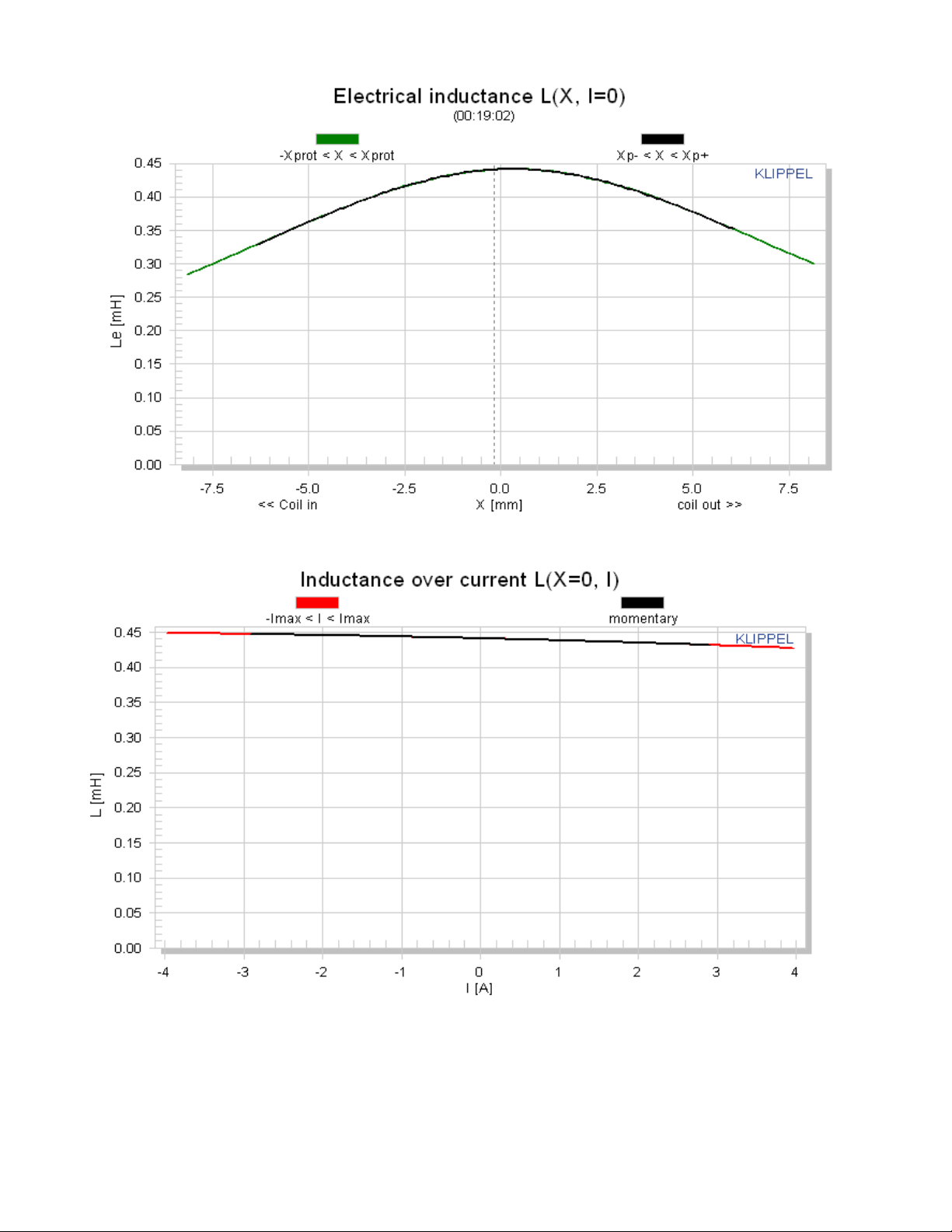
The flux modulation Bl(i) has two effects too. On the electrical side the back EMF Bl(i)*v produces
nonlinear distortion due to the multiplication of current i and velocity v. On the mechanical side the
driving force F = Bl(i)*i comprises a nonlinear term due to the squared current i. This force produces
similar effects as the variable term Le(x).
Nonlinear Parameters
The displacement limits XBL, XC, XL and Xd describe the limiting effect for the force factor Bl(x),
compliance Cms(x), inductance Le(x) and Doppler effect, respectively, according to the threshold
values Blmin, Cmin, Zmax and d2 used. The thresholds Blmin= 82 %, Cmin=75 %, Zmax=10 % and
d2=10% generate for a two-tone-signal (f1=fs, f2=8.5fs) 10 % total harmonic distortion and 10 %
intermodulation distortion. The thresholds Blmin= 70 %, Cmin=50 %, Z
harmonic distortion which is becoming the standard for acceptable subwoofer distortion thresholds.
Traditionally, Xmax has been defined as the physical overhang of the voice coil, 15% times the
physical overhang, or the point where BL has dropped 70% from its X=0 value (same as X Bl). The
additional nonlinear limits allow us to quantify the other factors that limit a loudspeaker’s performance.
max=17 % create 20 % total
These parameters are defined in more detail in the papers: “AN04
Displacement Xmax”, “AN05 - Displacement Limits due to Driver Nonlinearities.”, “AN17 - Credibility of
Nonlinear Parameters”, “Prediction of Speaker Performance at High Amplitudes”, “Assessment of
Voice Coil Peak Displacement Xmax”, and “Assessing Large Signal Performance of Loudspeakers”
Symbol Number Unit Comment
Displacement
Limits
X Bl @ Bl
min=82%
X C @ C min=75% 4.8 mm Displacement limit due to compliance variation
X L @ Z max=10
%
X d @ d2=10% 19.7 mm Displacement limit due to IM distortion (Doppler)
alpha Heating of voice coil by eddy currents
alphaOrg Heating of voice coil by eddy currents (without limits)
Rtv K/W thermal resistance coil ==> pole tips
rv Ws/Km air convection cooling depending on velocity
Rtm K/W thermal resistance magnet ==> environment
tau m min thermal time constamt of magnet
Ctm Ws/K thermal capacity of the magnet
thresholds can be changed in Processing property page
3.3 mm Displacement limit due to force factor variation
>6.0 mm Displacement limit due to inductance variation
– Measurement of Peak
Page 6

tau v s thermal time constant of voice coil
Ctv Ws/K thermal capacity of the voice coil
delta Tw K Temperature increase in Warm Resistance Mode
delta Tc K Temperature increase in Convection Mode
delta Te K Temperature increase in Eddy Mode
Pcoil(warm) W Pcoil in warm mode
Pcoil(conv) W Pcoil in convection mode
Ptv(mag.beg) W power heating the coil at beginning of magnet mode
Ptv(mag.mid) W
power heating the coil sampled in the middle of magnet
mode
Ptv(mag.end) W power heating the coil at end of magnet mode
Ptm(mag.beg) W power heating the magnet at beginning of magnet mode
Ptm(mag.mid) W
power heating the magnet sampled in the middle of magnet
mode
Ptm(mag.end) W power heating the magnet at end of magnet mode
f1 -0.006115 1/A coefficient (1) of Inductance over current (flux modulation)
f2 -0.000457 1/A^2 coefficient (2) of Inductance over current (flux modulation)
Bl0 = Bl (X=0) 4.6298 N/A constant part in force factor
Bl1 0.065773 N/Amm 1st order coefficient in force factor expansion
Bl2 -0.077099 N/Amm^2 2nd order coefficient in force factor expansion
Bl3 -0.00098838 N/Amm^3 3rd order coefficient in force factor expansion
Bl4 0.00034136 N/Amm^4 4th order coefficient in force factor expansion
Bl5 N/Amm^5 5th order coefficient in force factor expansion
Bl6 N/Amm^6 6th order coefficient in force factor expansion
Bl7 N/Amm^7 7th order coefficient in force factor expansion
Bl8 N/Amm^8 8th order coefficient in force factor expansion
L0 = Le (X=0) 0.44012 mH constant part in inductance
L1 0.0019246 mH/mm 1st order coefficient in inductance expansion
L2 -0.0031499 mH/mm^2 2nd order coefficient in inductance expansion
L3
-1.4492e005
mH/mm^3 3rd order coefficient in inductance expansion
L4 1.4141e-005 mH/mm^4 4th order coefficient in inductance expansion
L5 mH/mm^5 5th order coefficient in inductance expansion
L6 mH/mm^6 6th order coefficient in inductance expansion
L7 mH/mm^7 7th order coefficient in inductance expansion
L8 mH/mm^8 8th order coefficient in inductance expansion
C0 = Cms (X=0) 2.1454 mm/N constant part in compliance
C1 0.010852 1/N 1st order coefficient in compliance expansion
C2 -0.021891 1/Nmm 2nd order coefficient in compliance expansion
Page 7

C3 -0.00071187 1/Nmm^2 3rd order coefficient in compliance expansion
0
(
C4 4.2192e-005 1/Nmm^3 4th order coefficient in compliance expansion
C5 1/Nmm^4 5th order coefficient in compliance expansion
C6 1/Nmm^5 6th order coefficient in compliance expansion
C7 1/Nmm^6 7th order coefficient in compliance expansion
C8 1/Nmm^7 8th order coefficient in compliance expansion
K0 = Kms (X=0) N/mm constant part in stiffness
K1 -0.0083501 N/mm^2 1st order coefficient in stiffness expansion
K2 0.0042013 N/mm^3 2nd order coefficient in stiffness expansion
K3 0.00052573 N/mm^4 3rd order coefficient in stiffness expansion
K4 7.7367e-005 N/mm^5 4th order coefficient in stiffness expansion
Xpse 8.1 mm -Xpse < X < Xpse, range where power series is fitted
Parameters at the Rest Position
The value of the nonlinear parameters at the rest position (x=0) may be used as input for the traditional
linear modelling and may be referred as “linear parameters”. Please note that these parameters
depend on the instantaneous state of the driver (voice coil temperature, peak value of displacement)
and are presented for three different modes of operation:
Mode Properties
LARGE+WARM the transducer is operated in the large signal domain, the peak value of the
displacement is high (|x| < xmax), the variation of the parameters is not
negligible, the voice coil temperature is increased (D TV >
LARGE+COLD the transducer is operated in the large signal domain, the peak value of the
displacement is high (|x| < xmax), the variation of the parameters is not
negligible, the effect of heating is compensated while considering the cold voice
coil resistance Re
SMALL SIGNAL the transducer is operated in the small signal domain, the amplitude of the
excitation signal is sufficiently small, the displacement is small in comparison to
the allowed maximal displacement (|x| << xmax ), the variations of the nonlinear
parameters are negligible, the increase of voice coil temperature is negligible (D
TV » 0), the effects of the nonlinear, thermal and time-varying mechanisms are
negligible, the transducer behaves almost linear.
D TV =0).
) due to heating.
Linear Parameters
Symbol
Note:
Large +
Warm
Large +
Cold
Small
Signal
Unit Comment
for accurate small signal parameters, use LPM
module
Delta Tv =
29 0 0 K
increase of voice coil temperature during the
Page 8

Tv-Ta measurement
Xprot 8.1 8.1 4.1 mm
Re (Tv) 4.52 4.07 4.07 Ohm
Le (X=0) 0.44 0.44 0.38 mH
L2 (X=0) 1.21 1.21 0.46 mH
R2 (X=0) 1.62 1.62 1.77 Ohm resistance at the rest position due to eddy currents
Cmes (X=0) 305 305 303 µF electrical capacitance representing moving mass
Lces (X=0) 39.37 39.37 20.80 mH
Res (X=0) 52.47 52.47 25.33 Ohm
Qms (X=0,
Tv)
Qes (Tv) 0.35 0.32 0.44 electrical Q-factor considering Re (Tv) only
Qts (X=0,
Tv)
fs 46.0 46.0 63.4 Hz driver resonance frequency
Mms 5.600 5.600 5.600 g
Rms (X=0) 0.350 0.350 0.729 kg/s mechanical resistance of total-driver losses
Cms (X=0) 2.14 2.14 1.13 mm/N
Bl (X=0) 4.55 4.55 4.55 N/A
Vas 2.7958 2.7958 1.4702 l equivalent air volume of suspension
N0 0.074 0.082 0.082 % reference efficiency (2Pi-sr radiation using Re)
Lm 80.8 81.3 81.3 dB characteristic sound pressure level
Sd 30.43 30.43 30.43 cm² diaphragm area
4.62 4.62 3.06 mechanical Q-factor considering Rms only
0.33 0.30 0.38 total Q-factor considering Re (Tv) and Rms only
maximal voice coil excursion (limited by
protection system)
(imported) voice coil resistance considering
increase of voice coil temperature Tv
voice coil inductance at the rest position of the
voice coil
para-inductance at the rest position due to the
effect of eddy current
electrical inductance at the rest position
representing driver compliance
resistance at the rest position due to mechanical
losses
(imported) mechanical mass of driver diaphragm
assembly including voice-coil and air load
mechanical compliance of driver suspension at the
rest position
(imported) force factor at the rest position (Bl
product)
For accurate system modelling
parameters because they more closely reflect the parameters in their typical operating range.
“Large + Cold” parameters are preferable to “Small Signal”
Asymmetrical Nonlinearities
Page 9

A
symmetrical nonlinearities produce not only second- and higher-order distortions but also a dc-part in
the displacement by rectifying low frequency components.
For an asymmetric stiffness characteristic the dc-components moves the voice coil for any excitation
signal in the direction of the stiffness minimum.
For an asymmetric force factor characteristic the dc-component depends on the frequency of the
excitation signal. A sinusoidal tone below resonance (f<fS) would generate or force moving the voice
coil always in the force factor maximum. This effect is most welcome for stabilizing voice coil position.
However, above the resonance frequency (f>fS) would generate a dc-component moving the voice coil
in the force factor minimum and may cause severe stability problems.
For an asymmetric inductance characteristic the dc-component moves the voice coil for any excitation
signal in the direction of the inductance maximum.
Please note that the dynamically generated DC-components cause interactions between the driver
nonlinearities. An optimal rest position of the coil in the gap may be destroyed by an asymmetric
compliance or inductance characteristic at higher amplitudes. The module "Large Signal Simulation
(SIM)" allows systematic investigation of the complicated behaviour.
Bl Symmetry xb(x)
This curve shows the symmetry point in the nonlinear Bl-curve where a negative and positive
displacement x=xpeak will produce the same force factor
Bl(xb(x) + x) = Bl(xb(x) – x).
If the shift xb(x) is independent on the displacement amplitude x then the force factor asymmetry is
caused by an offset of the voice coil position and can be simply compensated.
If the optimal shift xb(x) varies with the displacement amplitude x then the force factor asymmetry is
caused by an asymmetrical geometry of the magnetic field and can not completely be compensated by
coil shifting.
Page 10

A
Kms Symmetry xc(x)
This curve shows the symmetry point in the nonlinear compliance curve where a negative and positive
displacement x=xpeak will produce the same compliance value
kms(xc(x) + x) = kms(xc(x) – x).
high value of the symmetry point xc(x) at small displacement amplitudes x » 0 indicates that the rest
position does not agree with the minimum of the stiffness characteristic. This may be caused by an
asymmetry in the geometry of the spider (cup form) or surround (half wave). A high value of the
symmetry point xc(x) at maximal displacement x» xmax may be caused by asymmetric limiting of the
surround.
Page 11

You can find a detailed description of these non-linearities and their remedies in the papers
“Loudspeaker Nonlinearities
Loudspeakers, and “Diagnosis and Remedy of Nonlinearities
Testing performed by Redrock Acoustics – www.redrockacoustics.com
- Causes and Symptoms, Assessing Large Signal Performance of
 Loading...