

Page 1
2.1 Channel Class D Amplifier
Model: MCA2250E
User Manual
daytonaudio.com
Page 2

Thank you for purchasing the MCA2250E 2.1 Channel Amplifier. It was designed and built to provide years of high quality
sound reproduction, and is ideal for use for music playback and computer audio systems. The amplifier includes features
like efficient Class “D” technology, independent amplifiers, selectable subwoofer crossover frequency, auto on/off circuitry,
and internal protection against shorted speaker loads, thermal faults, and overload conditions.
Features
• Independent high frequency and low frequency ampliers
• Efcient Class D technology
• Satellite level control
• Subwoofer level control
• Variable subwoofer crossover
:
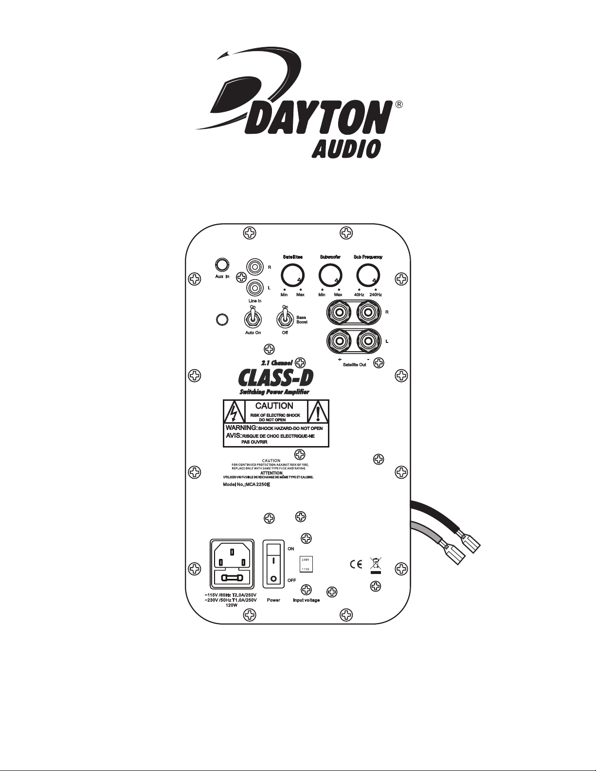
CONTROLS AND CONNECTIONS
POWER SWITCHES AND INPUT
1.) Master ON/OFF Switch:
The amplier is manually turned ON or OFF via this master
switch. When the power switch is moved to the “ON” position,
the amplier will be in one of two modes depending on the
“On/Auto on” switch position.
2.) Indicator LED:
When the master switch is on and the indicator LED is red, the
amplier is in standby mode. When the On/Auto-On switch is
in the “On” position, the LED will stay green, and the amplier
is fully active. In the “Auto-On” position the LED will be green
and will turn to red after 10 minutes without a signal
Note: The master power switch will turn off the amplier regardless of the “On/Auto on” switch setting.
3.) On/Auto-On Switch:
When the “On/Auto on” switch is in the “On” position the amplier will operate normally. When in the “Auto-On” position the
amplier will operate normally when a signal (via RCA input) is
present and go in “stand by” mode when idle (no signal present). It will take approximately 10 minutes for the unit to switch
from active to stand by mode. In standby mode the power draw
is less than 0.7W and heat generated is low therefore it is not a
problem to leave in the “Auto on” position indenitely.
Note: The Master “ON/OFF” power switch must be in the “ON” position to operate regardless of the “On/Auto on” switch setting.
4.) IEC Power Jack / Fuse Holder:
The unit comes with an IEC jack that permits removal of the
AC power cord. This allows the exibility of changing the power
cord for different countries. The IEC socket also houses the
main fuse holder. Plug the power cord supplied with the amplier into the amplier and a grounded wall outlet or appropriate
surge protector. In most 230V applications a separate power
cord will be required and is not included.
Fuse: Replace with only 5mm x 20mm, fast blow 3.15A, 250V
type fuse for 115V operation and 2.5A for 230V operation.
5.) AC Voltage Switch:
The unit is set at the factory for 115V U.S. operation; simply
connect the included IEC power cord to your wall outlet.
For 230V operation, move the voltage selector switch to the
230V position. When operating at 230V the internal fuse
located in the IEC socket should also be changed. In most
230V applications a separate power cord will be required
and is not included.
Note: Be sure to change the fuse to a 2.5A rating before
switching to 230V operation.
• Switchable +3dB bass boost @ 63Hz
• RCA line level and 3.5mm stereo inputs
• Thermal, overload and fuse protection circuitry
• LED power status indicator
LEVEL CONTROLS
6.) Satellite Level Control:
This adjusts the overall output level of the satellite amplier.
By adjusting both the satellite and subwoofer level controls,
the user will have the ability to blend the output levels of the
satellite and subwoofer speaker systems.
7.) Subwoofer Level Control:
Independently adjusts low frequency output level to the subwoofer only. Adjustment range is 0 ~ +5dB. Use this control to match
the subwoofer output level with the satellite output level.
8.) Subwoofer Frequency Control:
Independently adjusts low pass frequency to the subwoofer
only. Adjustment range of this active low pass crossover is 40
~ 240Hz with a 12dB / octave slope.
9.) Bass Boost (On/Off) Switch:
When in the “On” position the amplier subwoofer output is
increased 3dB centered at 63Hz. This will give the user added
bass output in the low frequency region.
Note: This switch should not be activated when the amplier is
being played at high volume levels, damage to the subwoofer
driver may result.
INPUT CONNECTIONS
10.) RCA Line Input:
RCA female connection accepts standard line level nominal
200mV p-p signal. This is suitable for connection to home equipment as well as mixing console outputs in studio applications.
11.) 3.5mm Stereo Input:
The unit also features a 3.5mm stereo input jack for quick
connection to computers, MP3 players and other portable
electronic devices.
SPEAKER OUTPUTS
12.) Satellite:
The two pair (left “L” and right “R”) of binding post located on
the front panel, each color coded red “+” and black “-”, contain
an active 12dB/octave high pass lter @ 150Hz for satellite
speaker connection. Load on each output must have a nominal
impedance of 8 ohm or higher.
13.) Subwoofer:
There is one set of speaker outputs, red “+” and black “-” wires,
located on the rear (PC board side) of the amplier module.
More specically at the bottom of the larger PC board that is
perpendicular to the front panel. This amplied output contains
an active 12dB/octave variable low pass lter for subwoofer
speaker connection. Load on output must have a nominal
impedance of 4 ohm or higher.
(2)
Page 3

(3)
Page 4

SPECIFICATIONS:
Satellite Section:
Speaker Impedance: 8 ohm
Power Output: 22W RMS x 2 @ 8ohm
Frequency response: 150Hz - 20KHz
THD: Less than 0.3% @ rated power
Signal to Noise Ratio: 90dB at rated power
Subwoofer Section:
Speaker Impedance: 4 - 8 ohm
Power Output: 50W RMS @ 4ohm
Variable Low Pass Frequency: 40Hz ~ 240Hz
THD: Less than 0.3% @ rated power
Signal to Noise Ratio: 90dB at rated power
Bass Boost: +3dB centered at 63Hz
General:
Crossover Slope: 12dB / octave low pass and high pass lters
Input Sensitivity: 235mV p-p
Auto Turn-On Sensitivity: 10mV
Turn-Off Time: 25 minutes
Power Requirements: 115V/60Hz or 230V/50Hz 120W
Stand-By Power Rating: 115V, < 0.5W*
Overall Dimensions: 10 7/16" (H) x 5 7/8" (W) x 2-3/4" (D)
Required Opening: 9 1/4" (H) x 4 5/8" (W)
* The MCA2250E complies with the CE EuP directive
Important Safety Instructions
To reduce the risk of electric shock, do not remove cover. No user serviceable parts inside. Refer servicing to qualied personnel. To
reduce the risk of re and shock do not expose unit to rain or moisture. The unit should be connected to an earth grounded AC electrical
socket. The unit should be operated in a well ventilated area. Minimum clearance is 2 inches from the ventilation openings.
Note: Unit is set at the factory for 115V operation. Be sure to change the fuse to a 2.5A rating before switching to 230V operation.
Warranty Information
Dayton Audio® products are constructed by industry experts, and are thoroughly tested before
shipment. Dayton Audio® products are warranted for the period of one year. This warranty is limited to manufacturer defects, either
in materials or workmanship. Dayton Audio® is not responsible for any consequential on inconsequential damage to any other
unit or component or the cost for installation or extraction of any component of the audio system. In the rare case of a product
failure, please contact your place of purchase or call our Customer Support Department at (937) 743-8248.
Warranty Limitations
There are no other warranties, either express or implied, which extend the foregoing, and there are no warranties of merchantability or tness for any particular purpose. The warranty will not cover incidental or consequential damage due to defective or
improper use of products. This includes but is not limited to burnt voice coils, overheating, bent frames, holes in the cone, or
broken lead wires.
This warranty gives you specic legal rights and you may also have other rights which vary from state to state.
Non-Warranty Service: If non-warranty service is required, the product may be sent to the Company for repair/replacement,
transportation prepaid, by calling (937) 743-8248 for details, complete instructions, and service fee charges.
MCA-12
(4)
© Dayton Audio®Last Revised: 12/9/2011
 Loading...