

Operating Manual
Basic Control
BC16 single-channel for matrix

Dear Customer,
Thank you for choosing a WALTRON daytime® lighting controller.
Your daytime® lighting controller is a high-quality product that was specially designed, along with
the daytime® LED lighting line, for aquatic and aquarium applications. It satisfies the most
demanding safety requirements.
The features of this daytime® product are described in detail in the following chapters. Please read
the operating manual carefully and completely. We would be happy to answer any questions that
you may have.
The entire team at WALTRON wishes you a "bright" future with our daytime® lighting!
Notice, warning and safety symbols
The European Standard prescribes the use of the following symbols for specific situations; they
are not intended to unsettle the user. They are a part of modern operating manuals for any
electrically operated appliance.
General description:
Warning!
Serious injuries can result from an electric
shock if you do not follow the information
marked by this symbol.
Notice!
The daytime® products may malfunction or be
damaged if the information marked by this
symbol is not observed.
Info
Sections marked by this symbol contain
helpful recommendations and tips for using
the daytime® products.
Information for disposing of the product in an
environmentally responsible manner
Compliance with EC directives
Proper and intended usage
This product is designed for private household usage. It may only be used to control WALTRON
GmbH's daytime® LED lighting systems for aquariums and terrariums.
Read and observe this entire operating manual before using the lighting controller for the first time.
The warranty does not cover damage or defects which have resulted from not observing the
information in the operating manual. Keep this operating manual accessible near the device. Make
sure that it is given to any subsequent users. WALTRON assumes no liability for the
consequences of improper usage.
For your safety
Warning!
Carefully read and observe the following
important safety information. In order to avoid an
electric shock:
Position the device in a suitable place to ensure
that it is not exposed to water (from condensation
or falling into water).
Info
WALTRON recommends making "drip loops" in
the converter cables to prevent water
(condensation) from running along the cable to
the converter or outlet.
Notice!
Make sure that all cables:
• have no kinks in them,
• are not routed over sharp edges,
• cannot be jammed or snagged,
and cannot come into contact with hot surfaces
(> 60 °C).
Warning!
If you notice that the power cable is damaged,
disconnect the device from mains power supply
immediately. Contact an authorized daytime®
service partner or the manufacturer (WALTRON
GmbH) directly.
Warning!
If the operating device's power cable or
secondary cable(s) are damaged, they must be
repaired, either by an authorized daytime® service
partner or directly by the manufacturer.
Never use a device which has a damaged or
defective power cable (operating device).
Warning!
Never open or repair the operating devices and
lights by yourself. Do not make any changes
which are not described in these operating
instructions. The operating device contains live
(current-carrying) parts (with 230 V AC). A fatal
injury can result from an opened device.
Repairs may only be made by authorized
daytime® service partners or by Waltron, using
only original spare parts and accessories.
Scope of delivery
1 lighting controller: Basic Control BC16 single-channel for matrix
1 operating manual
Features & functions
• Sunrise and sunset – simulating natural lighting conditions for day and night
• Easy to operate and program: directly at the device, using three buttons and a status LED
• Separately adjustable brightness level for each day or night light
• Demonstration mode with constantly changing day or night light
• Can be dimmed manually in real time
• Internal 24-hour clock (with about 15 minutes of power reserve)
• Shapely high-end enclosure with comfort control buttons
• Professional "Plug & Play" connector system manufactured by Binder – the controller is
simply inserted between the converter and the lighting: can also be retrofit!
• Operates the daytime® matrix lighting with up to 240 watts (24 matrix LED modules)
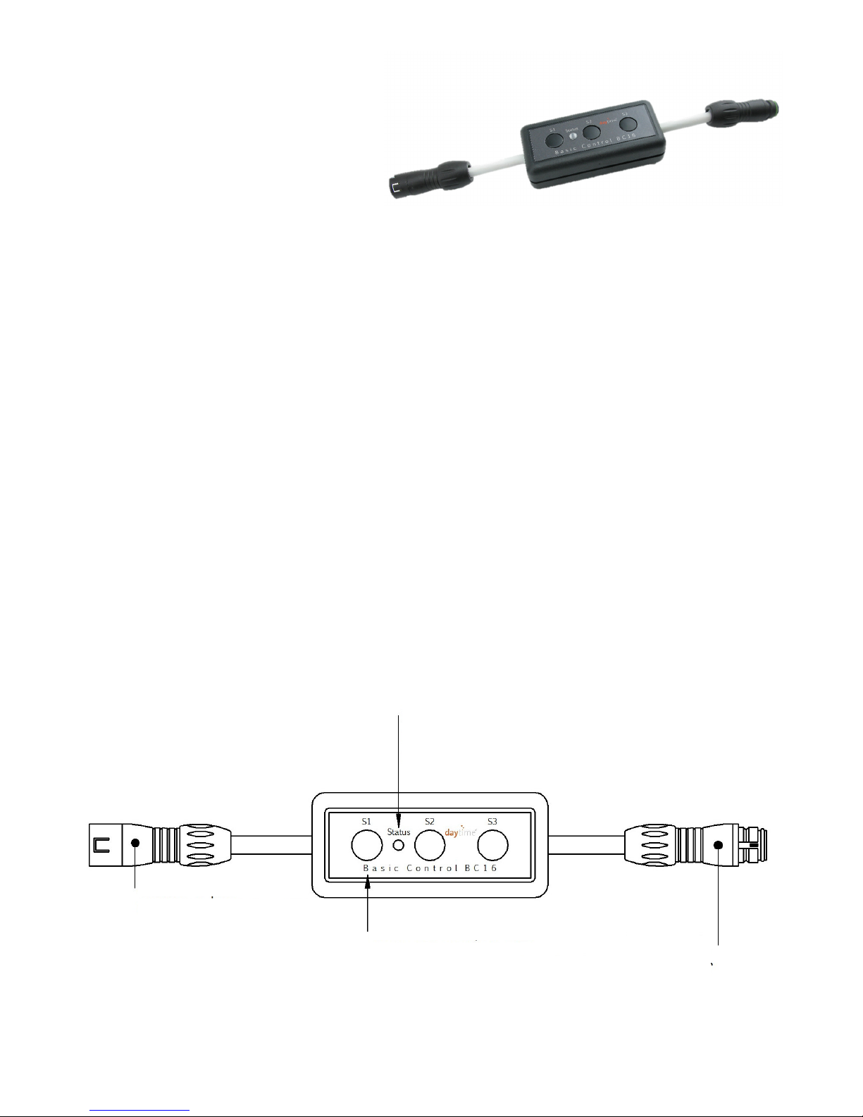
Device overview and explanation
Status LED
Green -> automatic mode
Green blinking -> sunrise or sunset
(for connecting light or distributor)
Control buttons: S1, S2 and S3
5-pin
plug
(for 24V converter
connection)
5-pole socket

Overview
The Basic Control BC16 lighting controller is designed for operating the "matrix" LED lights, with a
total output of max. 240 watts (24 matrix modules each at 10 watts). It can switch between day
and the night lighting, and has a consistent dimming function (sunrise/sunset). The brightness for
the day or night lighting has a stepless adjustment which can then be saved. A pause time (when
the light is completely off) can be enabled or disabled. If it is disabled, the light is only switched or
dimmed between the day and night lighting. If the pause is enabled, everything is switched off at
the specified start of the pause; the appropriate light (depending on the time) is then switched on
at the end of the pause.
The BC16 also has a fast-motion time-lapse function which can be used for test or demonstration
purposes. This shows the set or saved lighting program with shorter transition times in just 60
seconds.
The internal clock has a "power reserve"; it can run for an additional 15 minutes after a shut down
or after a power outage. The lights are turned off during this time. A quick periodic flashing of the
status LED indicates the status. The LED first flashes green and then, after 10 minutes, red.
There are three buttons (S1, S2 and S3) used for the settings and operations. A two-colour LED
(red/green) displays the status.
The following settings can be made using the three buttons:
• Current time (in 5 min increments)
• Start of sunrise (hour)
• Start of sunset (hour)
• Brightness of daylight 0 – 100%
• Brightness of night light 0 – 100%
• Transitional period between daylight and night light in 6 steps
(Duration of sunrise or sunset)
• Start of pause / switch-off time (hour) -> Light off
• End of pause / switch-on time (hour) -> Light on
• Restore the factory default settings
• Time-lapse function (faster run-through of light program in 60 seconds)
Note: The actual transition times may vary slightly depending on your system! The selected
transition interval applies only to the sunrise and sunset, but not for switching at the start and end
of the pause.
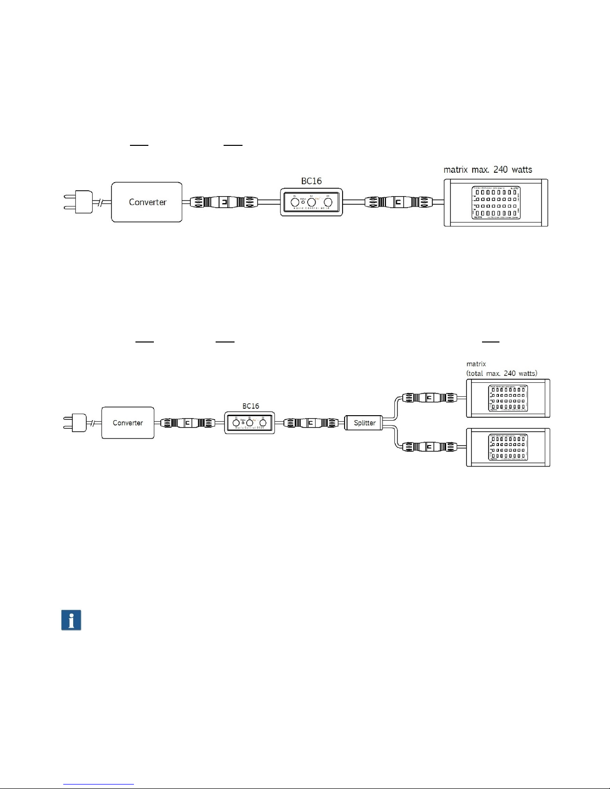
1. Setup and initial usage
All electrical connections and components (except for the power plug) should be connected to
each other according to the following examples. Observe any relevant safety instructions!
Example with one converter and one daytime® matrix light, with an output of max. 240 watts:
Example with one converter, one two-way distributor (optionally available), and two daytime®
matrix lights, with a total output of max. 240 watts:
2. Plug in the mains power plug or switch on the power supply /
supplies.
Note: During initial usage or after the power reserve of approximately 15 minutes has expired (e.g.
after a power failure), the status LED flashes red and displays: "Set clock!".

3. Setting the clock:
The time can be set at any time using the buttons. The hour can be adjusted hour-by-hour and the
minutes can be adjusted in 5-minute increments.
The time is set as follows:
1. Press the S1 button and hold down for max. 5 second
a. Press the S2 (HOUR) button so that the current hour is set.
Then adjust the minutes by pressing the
b. S3 button (in 5-minute increments)
2. Release the buttons. The status LED lights green after a short time, signalling automatic
mode.
The status LED will illuminate red each time the S2 or S3 button is pressed.
For example: the current time is 13:10
Press S1 and hold. Then, within no more than 4 seconds, press the S2 button 13 times. Then
press the S3 button twice (two 5-minute increments). Release the buttons. The status LED lights
green after a short time, signalling automatic mode.
During a power outage or after the power supply is disconnected, the internal clock runs for an
additional 15 minutes (the power reserve). In such a case, the Status LED will flash regularly to
signal that the clock is still running. The first 10 minutes are signalled with green flashes. After 10
minutes, the LED will flash red unit the power reserve is empty. The device will switch immediately
back to normal mode if the operating voltage is reapplied/reconnected during this power reserve
phase. The status LED will stop flashing once the power reserve is empty. The time on the clock
must be set again once this time has expired. All other saved values are retained. The status LED
will flash red once the operating voltage is applied. After the time is set, the status LED will
illuminate green again.
4. Setting the start of sunrise and sunset:
Press and hold S1 for about 8 seconds until the status LED illuminates red. Then release S1.
Repeatedly press the corresponding button (e.g. S2 for start of sunrise; S3 for start of sunset) the
proper number of times according to the desired time
(for example Sunrise start should be 06:00 -> then press S2 6 times / Sunset start should be 18.00
-> then press S3 18 times ). Press the S1 button to save and start normal operations.
Note: You should always specify both of these time points. However, if only one time point is
changed, the other time point will automatic be set to 0:00!

5. Setting the brightness of daylight and night light:
Press the S2 and S3 buttons at the same time. The status LED will illuminate red. First, daylight is
activated; it can be dimmed using the S2 and S3 buttons. The connected light will blink once the
maximum value is reached. Press the S2 button (to dim) or the S3 button (to brighten) to adjust
the lighting. The status LED will flash red quickly to confirm this action. Press S2 and S3 at the
same time to switch between daylight and night light. The night light is also adjusted by pressing
S2 and S3. It can be dimmed to a value of 0% (off). The device will return to normal operations if
the S1 button is pressed or if no button is pressed for about 5 – 6 seconds. The status LED will
illuminate green again. The adjusted values are saved automatically.
Note: If the brightness for the day and/or night light changes during the sunrise or sunset, the
sunrise/sunset is terminated as soon as the change is finished and the light is displayed according
to the time. For example: The selected transition time for sunrise and sunset is 30 minutes. The
brightness is changed during the transition from daylight to night light. Thus, after this changed
value is applied, the controller will "jump" directly to the night light phase.
6. Setting the transition period (duration of sunrise and sunset):
The transition period (the duration of the change from daylight to night light stored and vice versa)
can be adjusted at any time during normal operations. To set this, press the S2 button briefly, five
times in succession. The status LED will start to blink. The blinking pattern indicates the transition
stage, as follows:
One time blinking red – pause: Transition stage 1: 0 min (
only switches, without a transitional period
)
Two times blinking red – pause: Transition stage 2: 1 min
Three times blinking red – pause: Transition stage 3: 5 min
Four times blinking red – pause: Transition stage 4: 15 min
Five times blinking red – pause: Transition stage 5: 30 min
Six times blinking red – pause: Transition stage 6: 60 min
The stage can be selected by pressing the button S2 (-) or S3 (+). The corresponding blink code
will be displayed immediately after the change is made. You can also wait and observe the
change. After you have selected the desired time for the transition phase, press the S1 button to
save your selection. The normal operation mode will then resume.
7. Setting the start and end of the pause:
As a special function, a pause time can be set. The light will be switched off during the specified
pause start and pause end.
To set the start of the pause, press the S2 button and hold it down until the status LED starts to
blink red. Then press the S1 button to specify the number of hours (e.g. pressing zero times =
00:00 / press twice = 02:00). Then release the buttons. The red status LED will then return to
green after a short time; this indicates that normal operations have resumed.

To set the end of the pause, press the S3 button and hold it down until the status LED starts to
blink red. Then press the S1 button to specify the number of hours (e.g. pressing zero times =
00:00 / pressing six times = 06:00). Then release the buttons. The red status LED will then return
to green after a short time; this indicates that normal operations have resumed.
Note: To disable the pause feature, set the start and end of the pause to 00:00. First press S2 until
the status LED illuminates red. Then release S2 (S1 is not pressed, so the time is set to 0:00).
Wait until the status LED is green. Press the S3 button until the status LED illuminates red. Then
release S3 and wait until the LED turn green.
8. Factory settings:
The BC16 has factory default settings and can be reset at any time as follows:
1. Disconnect the power supply.
2. Press and hold both the S2 and S3 buttons.
3. Connect the power supply.
4. The Status LED acknowledges the reset to factory settings by rapidly flashing
red/green.
5. Release buttons S2 and S3.
Stored default settings:
Sunrise start: 08:00
Sunset start: 21:00
Pause: Disabled
Brightness of daylight: 100%
Brightness of night light: 0%
Transition period: Stage 3 (5 minutes)
Note: When the factory default settings are loaded, the internal clock is set to 00:00 hours and
must then be correctly set to the real time.
9. Time-lapse function (special mode):
The BC16 has a time-lapse mode that can be used for testing purposes or for checking your
specified values. When it is enabled, the clock runs several times faster and shows the specified
light program in fast motion in 60 seconds. Instead of the standard transition periods used in the
normal operating mode, shorter (only a few seconds) transition times are used. This can be
enabled or disabled during operations. When the time-lapse function is disabled, the clock
resumes running with its previously set time, so that it does not need to be set. You can enable
and disable the time-lapse function as follows:
Press the S1 button briefly five times in succession in order to switch the time-lapse function ON
or OFF.
If the time-lapse function is enabled, the status LED flashes alternately red/green. Buttons S2 and
S3 are disabled in time-lapse mode.

10. Brief overview of the settings
Setting Procedure
Time
Press and hold S1. Select the hour with S2 and the minutes with S3 (in 5-minute
increments).
for example: 20:15: press S2 20 times (= 20:xx); press S3 3 times (= XX:15)
Always set the hours before setting the minutes, since the minute value is set to 00 after
the hours are set!
Your settings will be saved automatically after a short interval of no pressed buttons.
Start of sunrise and sunset
(the hour)
Press and hold S1 for about 8 seconds until the status LED illuminates red. Then
release S1. Use S2 to select the number of hours for the sunrise start, and S3 for the
sunset start.
for example: Press zero times = 00:00; press 6 times = 6:00; press 21 times = 21:00
You must always specify both of these time points. However, if only one time point is
changed, the other time point will automatic be set to 0:00!
Press S1 to apply/save settings
Brightness
Daylight and night light
(0 – 100%)
Simultaneously press S2 and S3 to select day/night light. Dim with S2 (-); brighten
with S3 (+).
Apply/save with S1. Or settings will be saved automatically after a short interval of
no pressed buttons.
Start of pause (full hour)
Press and hold S2 until the status LED turns red. Then select hours with S1.
for example: Press zero times = 00:00; press twice = 02:00.
Your settings will be saved automatically after a short interval of no pressed buttons.
End of pause (full hour)
Press and hold S3 until the status LED turns red. Then select hours with S1.
for example: Press zero times = 00:00; press five times = 05:00.
Your settings will be saved automatically after a short interval of no pressed buttons.
Transition period
(6 stages)
Press S2 briefly five times. LED displays red "blink code". Buttons S2 and S3 for
selecting one of the 6 stages:
1x blinking = without transition time / 4x blinking = transition time approx. 15 min
2x blinking = transition time approx. 1min / 5x blinking = transition time approx. 30min
3x blinking = transition time approx. 5min / 6x blinking = transition time approx. 60min
Press S1 to apply/save settings
Factory settings
Disconnect power supply > Press and hold S2 + S3 > Connect power supply > Status
LED flashes rapidly alternately red/green > Release buttons
Note: When the factory default settings are loaded, the internal clock is set to 00:00 hours
and must then be correctly set to the real time.
Time-lapse
Press S1 quickly 5 times in succession to enable/disable the time-lapse function.
The status LED flashes alternately red/green when this function is enabled.

11. Technical specifications
Dimensions L/W/H (without connecting cables): 90 x 40 x 26 mm
Length of connecting cables (primary / secondary): approx. 90 mm (including plug and socket)
Weight: approx. 80 g
Operating voltage: 24 VDC (safety extra low voltage)
Max. load: 24 matrix LED-modules
Protection degree: IP20

Warranty notice
We have a 24 month warranty for daytime® products that we deliver within the EU.
Exceptions are damages due to non-compliance with the operating manual or other improper
handling.
If, contrary to expectations, you have grounds for a complaint within this warranty period, please
fill out and submit the enclosed warranty card to your nearest daytime® dealer.
daytime® – a trademark of:
Sapelloh 51
31606 Warmsen, Germany
Tel.: +49 (0) 5767 / 941 439 – 0
Fax: +49 (0) 5767 / 941 493 – 15
BA-BC16 single-channel for matrix
E-Mail: info@waltron-gmbh.com
92-0013 V.04
www.daytime.de | www.waltron-gmbh.com
We reserve the right to make changes. We assume no liability for printing errors.
 Loading...