

Page 1
TOOLS NEEDED
BILL OF MATERIALS
• Press or vice ( Daystar tool KU70091)
• Retaining clip pliers
• Floor jack
• Jack stand (s) 4
• Wheel chock
• Grease ( poly lube gun KU11005)
• 3/4 drive ratchet
• 10” 3/4 extension
• 13/16 wrench and 13/16 socket
• 7/8 wrench and 7/8 socket
• Measuring tap
• 21mm wrench
• 21mm socket
• Cut off wheel
Jeep JK Products
• KJ09138 3/4” Front & rear lift
• KJ09137 1 3/4” Front & rear lift
• KU09059 EVS Foam bump-stops
• KU09060 EVS Foam bump-stops
• KU70032 Ft upper control arms
• KU70033 Rear upper control arms
• KU70037 Rear lower control arms
• KU70091 poly flex tool
• KU11005 Poly lube gun
Part # Description Qty
S11096
S11100
BU70034
M00492
M00494
M03515
S10135
S10616
S10617
S10818
S10593
S10205
S10205
S10888
P11183
Lower arm 2
Rod end 2
Hardware kit 1
Bushing 2
Bushing 2
Bushing 4
Washer 4
Steel ball 2
C-clip 4
1-14 Jam nut 2
Tubing 2
9/16 Bolt 4
9/16 Lock nut 4
Washer 4
Thread lock 1
KU70034
2007 to Current Jeep JK control arm kit
Hells gate, Moab UT
www.Daystarproducts.com
Tech Support Contact Info
Tech@DaystarWeb.com
Phone: 623.907.0081
Instruction Sheet P11240-01
2007 Daystar Products International Inc.
Page 2
Thank you for choosing Daystar Products
Daystar recommends a certified technician install this system . In addition to
these instructions , professional knowledge of disassemble/reassembly procedures as well as post instructions checks must be known. Attempts to install this
system without this knowledge and expertise may jeopardize the integrity and/or
operating of the vehicle.
Please read all the instructions before beginning the installation. Check the kit
hardware against the parts list. Be sure you have all the needed parts and understand where they go. If anything is missing , do not proceed with the installation, Call Daystar Products to obtain needed items.
.
With both control arms installed , install the tires and lower
12
off the jack stands so the vehicle is on the ground.
13.
With a 21mm wrench and socket wrench tighten to 75ft lbs.
Product Use Information
As a general rule, the taller a vehicle is the easier it will roll. We strongly recommend , because of rollover possibility, that seat belts and shoulder harness be
worn at all times. Avoid situations where a side rollover may occur.
Braking performance and capabilities are decreased when significantly large/
heaver tires and wheels are used. Take this into consideration while driving,
Also , speedometer recalibration is necessary when larger tires are installed.
Do not add, alter, or fabricate any factory or after-market pa rt s whi ch inc rease
vehicle height over the intended height of the Daystar Product purchased. Mixing
component brands, lifts, and/or combining body lift with suspension lift voids all
warranties. Daystar makes no claims regarding lifting devices and excludes any
and all implied claims. We will not be responsible for any products that are altered.
Notice to Dealer and Vehicle Owner
Any vehicle equipped with any Daystar Product must have the “Warning to
driver” decal installed on the sun visor or dash. The decal is to act a constant reminder for whoever is operating the vehicle of its uniq ue h andl i n g characteristics.
INSTALLING DEALER— Its is your responsibility to install the warning decal
and forward these instructions on too the vehicle owner for review and to be kept
in the vehicle for service life.
After installation occurs, a qualified alignment facility is required to align the
vehicle to factory specs.
14. With the control arm installed and hardware tightened, a
wheel alignment will need to be done at this time.
15.
Check bolts and nuts after 500 miles and every 3000 or offroading.
16.
Lube the joints every 6 months or every other oil change.
Page 3
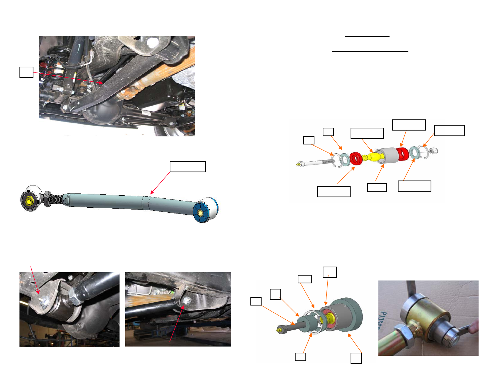
9.
Remove one control arm at a time.( 1 )
1
10.
11.
Install the Daystar lower control arm assembly with the bend to
the inside.
Bend
Install the front and rear 9/16 bolt and nuts and washers. Finger
tighten the nuts.
Installation steps
Poly Flex joint assembly
1. Using a retaining clip pliers install the C-clip (1) into the Steel shell
(4) then place the washer (2) into the shell (4).
2. Put a small amount of poly-lube over the pol y-flex bushing (3) then
install it over the steel washer (2)in the steel tube.(4)
3. Put a small amount of poly-lube over the steel ball (5) and then install it
in the steel tube (4) then install the other poly-flex bushing (6 ) over the
steel ball (5) .
4. Using the ploy-flex joint tool.( KU70091) Place the assembly (2)into
the large tool (1)and the place the washer (3 ) and C-clip (4)over opened
end off the assembly (2).
5. Place the small tool (5) over the washer (3) and push the 7/16 bolt (6)
through the assembly(2) and thread on the 7/16 nut.
6. With a 5/8 wrench and 5/8 ratchet on the bolt and nut tighten them down
so you can install the c-clip (4) using a c-clip pliers.
7. Repeat step's on the other threaded rod end.
1
3
2
6-M00494
2
5-S10616
4– ref
3-M00492
1- S10617
2- S10135
5
6
4
1
Page 4

Control arm assembling steps
Installation steps
1. Lube the 2 poly bushing ( 1) then install them into the control
arm.(2)
2. Push the steel sleeve( 3) into the bushings.
1
2 3
3. Install the S10818 1-14 jam nut (4) onto the rod assembly (5) .
4 5
4. Install the control arm assembly ( 2 ) onto the rod assembly ( 5 ).
5. Set the length of the arm to stock length if not lifted. If lifted add
a .250 to the length over 2.0” of lift. This is only a starting length.
You will need a wheel alignment to get the arms set to the right
length.
6.
Raise up the jeep and place floor jacks under the frame. Place
7.
wheel chocks behind the rear wheels.
Remove the wheels and place the jack under the front axel and
support it.
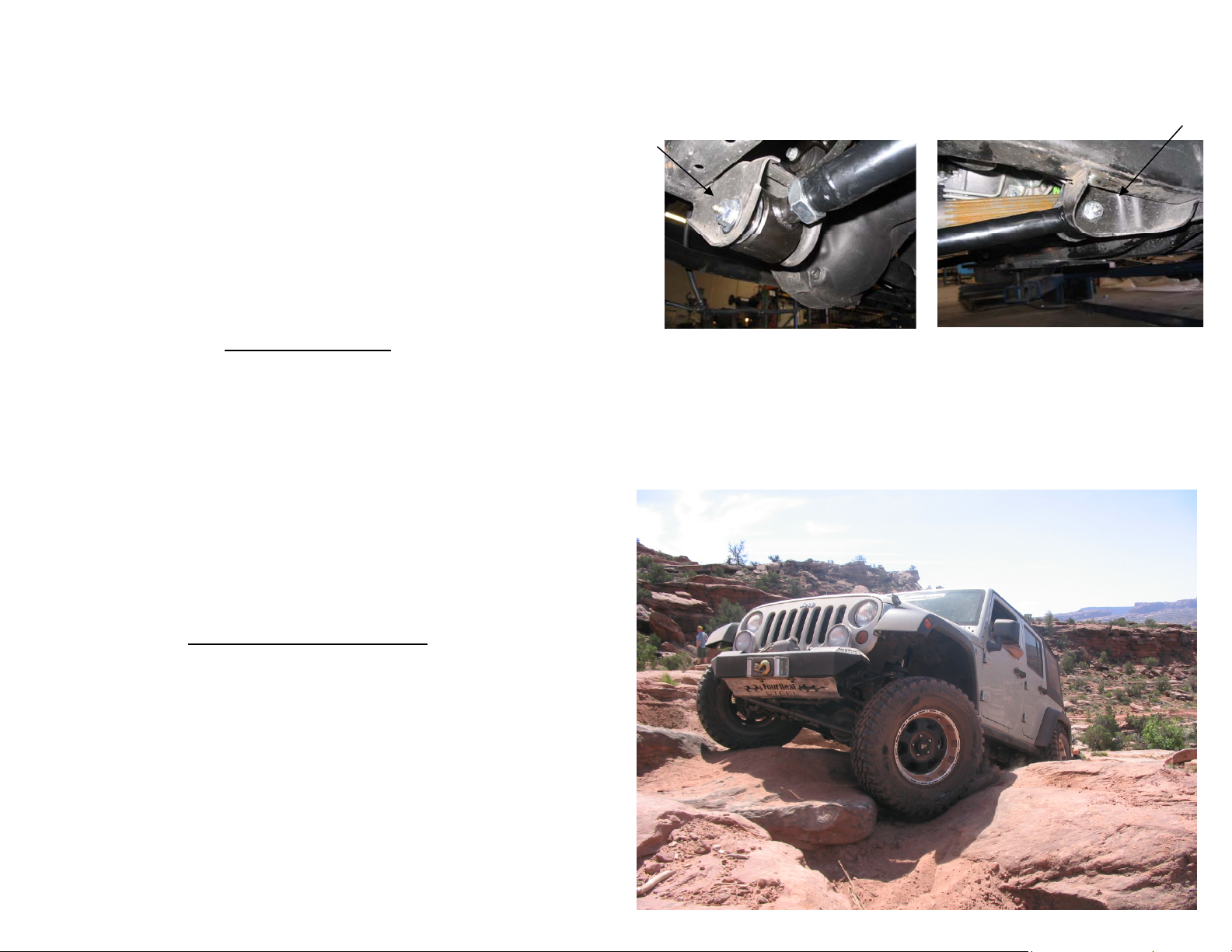
8. With a 21mm wrench and socket remove the front lower control
(4) arm bolts (3).
5
2
 Loading...